


Rolls-Royce Spirit of Innovation breaks world records for electric aircraft speed
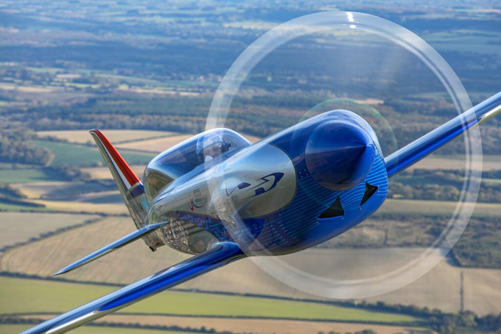
(Courtesy of Rolls-Royce)
Fast forward
Peter Donaldson examines the design and technology that went into making this electric aircraft a record-breaker
Electric aviation is roughly where piston-powered flight was in the 1920s and ’30s, in that record-breaking really matters to the credibility of the idea almost as much as to the impetus it gives to the development of electric aircraft technology. Against this backdrop, Rolls-Royce led a team tasked with building the world’s fastest all-electric aircraft as part of its Accelerating the Electrification of Flight (ACCEL) initiative.
The underlying motive was to create electric powertrain technology capable of safely delivering high power for short periods, and a battery capable of rapidly discharging and recharging while keeping the degradation of its energy capacity to a minimum – characteristics suited to intra-city urban air transport vehicles including eVTOL craft.
Partners in the £6.9 million project included electric motor and controller manufacturer YASA and aviation start-up Electroflight, which is now part of Evolito. Half of the project’s funding came from the Aerospace Technology Institute, in partnership with the UK government’s Department for Business, Energy & Industrial Strategy and Innovate UK. Electroflight designed the entire powertrain and battery system as well as modifying and assembling the aircraft.
Beyond record-breaking and technology development, a further key objective was to engage with the automotive supply chain and work with it to create what Rolls-Royce refers to as a new aerospace supply ecosystem, as well as positioning the company to offer power systems to the urban air mobility market.
The aircraft, named Spirit of Innovation, achieved its goal on 16 November 2021 when it registered a maximum speed of 623 kph (387.4mph), with Phill O’Dell, Rolls-Royce test pilot and director of flight operations, at the controls. The record makes it officially the fastest electric vehicle in the world, the experimental Japanese L0 series maglev train and the Little Giant land speed record car included.
The top speed run was part of a series of flights in which the aircraft also averaged 555.9 kph over a 3 km course, beating the existing record by 213.04 kph. The Spirit of Innovation subsequently averaged 532.1 kph over a 15 km course, 292.8 kph faster than the previous record, and was flown by Electroflight’s Steve Jones.
The third record broken was for the fastest time to climb to 3000 m, also with Steve Jones at the controls. This took the Spirit of Innovation 202 seconds, yielding an average climb rate of almost 2924 ft/minute, breaking the previous record by 60 seconds.
In all cases, the previous records were set in 2017 using an Extra 330LE racer modified by Siemens eAircraft, now part of Rolls-Royce. The new records have been verified by the Federation Aeronautique Internationale (FAI), which is the internationally recognised body.
Other markers that the Spirit of Innovation laid down included that of the most powerful electric aircraft and the highest voltage, most energy and power-dense battery system integrated into an aircraft so far.
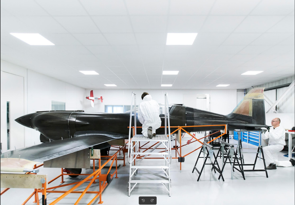
Converted kit racer
As the project’s focus was on developing the energy storage system (ESS) and the powertrain, not on the airframe, Electroflight looked for an existing aircraft that would make a good candidate for conversion.
The machine it chose was the Nemesis Air Racing NXT, which is available in kit form. It has a monocoque airframe made from carbon fibre reinforced plastic (CFRP), highly efficient aerodynamics essential to air racing and enough volume ahead of the wing to accommodate an oversized powertrain.
A low-wing monoplane, a standard Nemesis NXT is 23 ft long, has a wingspan of 24 ft and weighs 1500 lb empty. It features retractable landing gear, a steerable tail wheel, split flaps and side stick controls in its side-by-side two-seat cockpit, although in Spirit of Innovation guise, it is a single-seater to save weight.
Two NXT kits were delivered to Electroflight in May 2018. One would become the record-breaking machine, while the other would serve as a ground test vehicle dubbed the Ion Bird, the name being an electrically charged nod to the traditional term ‘iron bird’ for an aircraft-like rig dedicated to ground tests and never intended to fly.
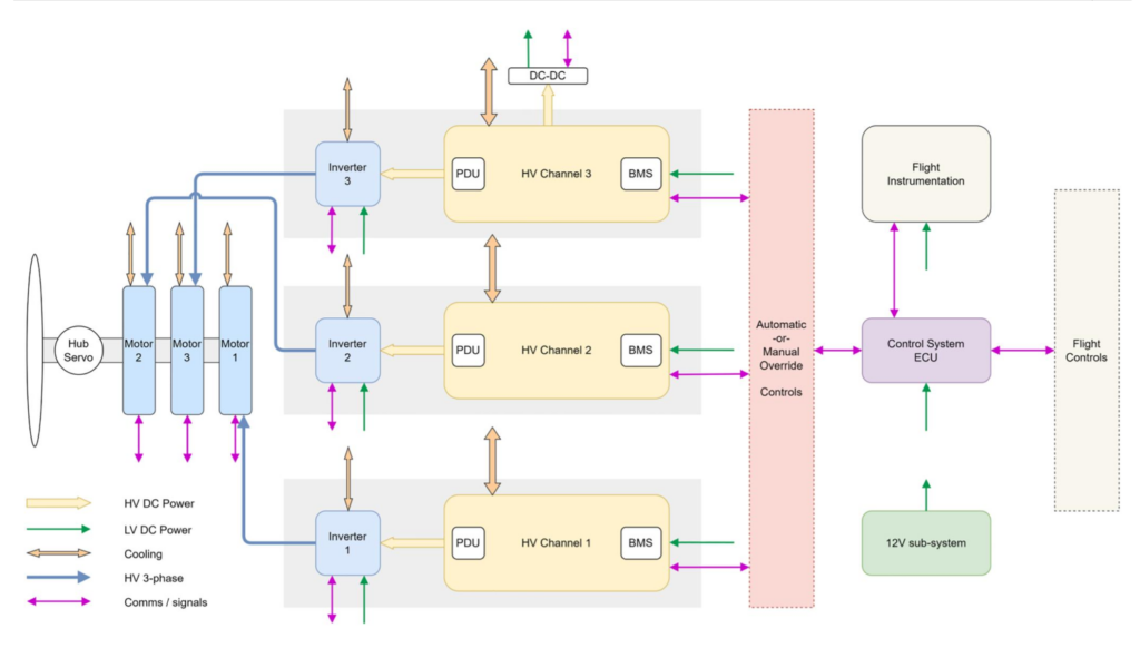
Powertrain architecture
With a clear eye on future commercial passenger operations, the powertrain could not sacrifice safety in favour of speed, so it has triple redundancy. What are effectively three separate powertrains only converge at the pilot’s power lever (which has the look and feel of a conventional aircraft throttle) and at the propeller.
The battery system consists of three galvanically isolated battery packs, each with its own BMS, PDU and inverter. Each inverter takes high-voltage DC from its battery pack and sends high-voltage AC to one of the three axial flux permanent magnet motors. Each inverter also has its own potentiometer, through which it receives torque demands from the power lever.
The motors are bolted together in a stack and drive a common output shaft running through them all, and is supported front and rear by grease lubricated bearings in aluminium bearing housings. The motors drive the propeller directly.
There is also a DC-DC converter that feeds the aircraft’s 12 V subsystem that in turn powers loads including each BMS, the control system ECU and the flight instrumentation, for example.
Each BMS exchanges signals with and receives power from the control system, which is automatic but with full manual override facilities that give the pilot complete control.
(Courtesy of Electroflight)
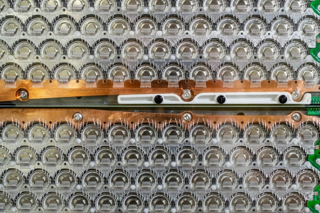
Cell and supercell
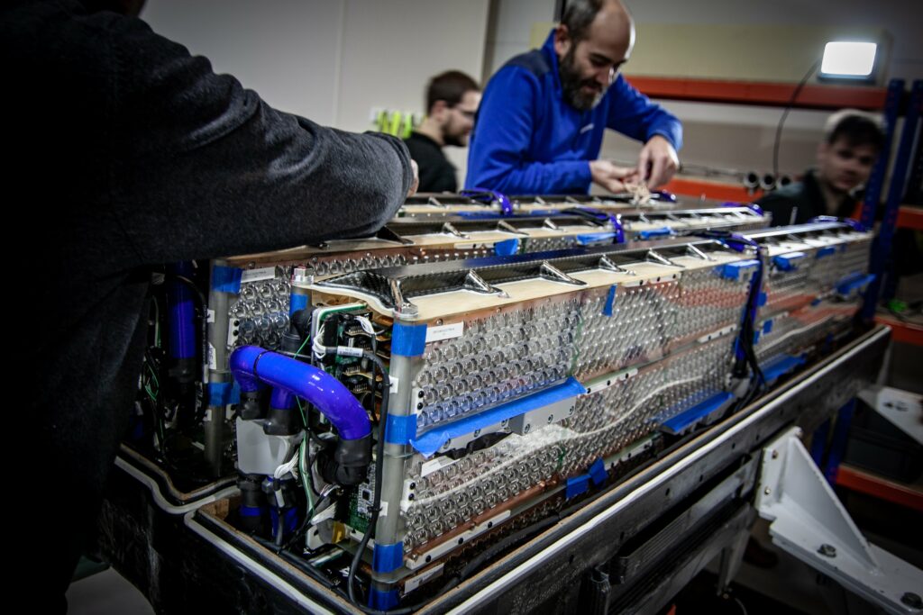
As the battery is the most challenging technology, and a bespoke solution was the only option, most of the development effort went into the ESS. This involved selecting the cells, their parallel and series interconnection scheme, sensor network, thermal management system, enclosure and venting system.
In designing and constructing the pack, Electroflight turned for inspiration to the motorsport and automotive sectors, which have both commonalities with and differences from aviation in terms of battery requirements, and have developed methodologies and components that could expedite the project.
Cylindrical cells were found to be better than pouch and prismatic cells in terms of gravimetric energy density (kWh/kg) for the power required, and provided multiple verified heat extraction techniques used in the motorsport industry for similarly demanding applications, according to Electroflight’s Timothy Bingham in a detailed report on the project*.
The chosen cells are 18650 cylindrical format VTC6s from Murata. Rated at 3.6 V nominal, they feature a lithium manganese cobalt oxide cathode and a graphite anode, and both positive and negative terminals are accessed at the top. This chemistry was chosen because it supports discharging all the energy in the ESS in a 10-minute mission, at a nominal discharge rate of 6C, and rapid recharging, allowing multiple flights in a single test period, Bingham notes.
The battery interconnection scheme’s basic building block is the 4.2 V supercell, which consists of 12 cells connected in parallel. Next, 15 supercells are connected in series to form a 63 V module half.
Two module halves are then connected in series to make a 126 V module, then six such modules in series make a 756 V channel, all voltages being maximal. Three of those channels are galvanically isolated from each other for independence and redundancy. The ESS therefore contains a total of 6480 cells, with a total energy of around 70 kW/h and a peak power of a little over 660 kW.
(Courtesy of Electroflight)
Preventing thermal runaway
To minimise the risk of thermal runaway, the team devised a three-part strategy. First, it sought to reduce the probability of short-circuits in the cells, second to detect any thermal event as early as possible, and third to slow any thermal propagation within the pack and to contain the event for long enough for the pilot to land safely and get out of the aircraft.
A cell capacity of around 3 Ah is fairly small for 18650 lithium-ion cells, but it’s a conservative choice driven by the desire to limit the amount of energy a single cell could release in a thermal runaway.
The selected cells also include a current interrupt device in the form of a disc that ruptures at a set pressure, breaking the electrical connection between the positive terminal and the current collector disc, and relieving the pressure within the cell by preventing resistive heating as no current can flow thorough it.
Bingham also notes that the cell is safe up to 80 ºC and that internal resistance falls as temperature rises. The latter provides a degree of self-limiting in terms of temperature, although as the bus voltage falls so currents increase to deliver the same power level.
Minimising the risk of thermal runaway requires operating each cell as far away from its temperature limit while allowing the pack to develop enough power to break the speed records, which is the key challenge for the thermal management system.
Like the ESS, the thermal management is divided into three independent sections, with a dedicated pump for each channel. Each pump feeds coolant through a flow-balanced manifold to all the modules in its channel, while the internal geometry of each cooling plate is designed to ensure appropriate cooling for each cell.
As a key part of the pre-flight routine, all the cells were charged, balanced and thermally pre-conditioned to ensure equal loading and a predictable temperature rise for consistent, safe performance.
The pack is extensively monitored, with humidity measured at pack level and has dry-air purging if needed. Every cell is monitored for temperature, while the voltage is measured at each of the 540 parallel connections.
The pack also contains sensors designed to detect volatile organic compounds, whose presence is an early indication of cell venting, along with pressure spikes that warn of cell disc ruptures. Insulation resistance between the HV conductors and chassis earth is also monitored to warn of potential short-circuits.
In flight, telemetry sends all this information to the ground team, while the cockpit instrument panel provides the pilot with a subset sufficient to make quick safety-related decisions, such as switching off a faulty channel or channels in the ESS before making an emergency landing.
Bingham stresses that the cell layout and the internal configuration of each channel are also designed to minimise the risk of thermal runaway. Every cell is positioned so that it can vent into free volume so that gases and hot particles can escape easily through the channel’s vent system. The ESS is compartmentalised throughout and includes thermal breaks and barriers, while all the materials meet UL94 V0 flammability standards.
The ESS also has a containment system that is designed to ensure that a landing can be made and the pilot can get out safely within 10 minutes of an indication of a thermal event. As the ESS case is part of the airframe structure and is made of CFRP, which does not resist high temperatures as well as structural metals typically do, it has to be protected from particles at up to 1000 ºC ejected from any venting cells.
This, says Bingham, was achieved with an air gap between the cell top cap and the case, and with a specialised thermal barrier material that can withstand ablation from the hot particles and insulate the CFRP well enough for it to retain its structural strength. The thermal barrier material is made from Portuguese cork, on which Amorim Cork Composites worked with Electroflight.
Gases leave the ESS case through a breather that accommodates normal pressure changes with temperature and altitude, and also opens instantly to serve as an emergency vent when the pressure reaches a set level. The gases then pass through a dedicated duct and out of the belly of the cowling.
There is also a nitrogen purging system that can run for up to 15 minutes to stop gases from reaching an explosive concentration in any of the ESS channels, and a NACA duct that can feed fresh air into the cockpit.
(Courtesy of Electroflight)
Thermal management system
Not only was the thermal management system crucial to the safety and reliability of the Spirit of Innovation’s powertrain, it was also crucial to breaking the records because it was clear from the first analysis that the system’s performance would be thermally limited, in large part because of the internal resistance of the cells.
Bingham points out that the apparently modest goal of making two flights per day was more challenging than it might first appear, because it meant cooling the 360 kg ESS down between flights from 80 ºC to 17 ºC while it was being charged for its next flight.
While the three ESS channels, each of which is effectively a battery pack in its own right, have their own independent pumped supply of water ethylene-glycol (WEG) mix, they all share a single motor. Three more pumps are double-headed units that each feeds an inverter with WEG and a motor with cooling oil, which is then passed through radiators divided into sections dedicated to each ESS channel’s battery, inverter and motor; just two radiators serve all the electrical machines and battery channels.
“Having a single motor for the three battery channel pumps was not a safety concern since, unlike for the electric machines, the channel’s internal thermal heat capacity was sufficient to prevent overheating in case of failure of the ESS cooling system,” Bingham notes.
The radiator sections dedicated to the battery coolant loops are larger in surface area than those of the electrical machines, because in the former the temperature difference between the coolant and the ambient air is smaller.
The DC-DC converter that supplies the LV system from the HV supply is air-cooled to save weight.
The cooling system components form a cooling pack that is mounted underneath the ESS case in a cowling.
(Courtesy of Electroflight)
Stacked pancakes
The three axial flux AC motors are YASA’s 750R model that together provide a thermally limited 400 kW (536 bhp), although each motor is capable of delivering 200 kW peak power at 700 V on a dynamometer with a coolant inlet temperature of 60 ºC, according to company data, offering a gravimetric power density of more than 5 kW/kg. The stack of three weighs 111 kg, and the claimed efficiency is almost 95%.
The motors have a yokeless and segmented armature configuration, from which the company takes its name. The armature segments form discrete pole pieces that allow them to be made from a soft magnetic composite material that can be pressed into various shapes, in turn eliminating the need for complex laminations and the associated machining operations. YASA says the configuration also simplifies the windings and makes the motor easier to cool than earlier axial flux designs.
Rigid and easy to mount thanks to their simple ‘pancake’ shape and compact dimensions of 98 mm axial length and 368 mm diameter, they are designed to be stacked to create high-power combinations. The stack is mounted in a frame bolted to the front of the battery enclosure, which carries the static and dynamic loads to the airframe. The airscrew they drive is a three-bladed controllable pitch unit from MT-Propeller, which spins at 2200 rpm.
The inverters are Sevcon Gen 4 size 10 units, which complement the motors well in terms of their current capabilities and position sensor integration, according to Bingham. Sevcon is now part of BorgWarner.
Electrical safety
A key electrical safety feature the aircraft has in common with modern EVs is the High Voltage Interlock Loop, which passes through the PDU and to all the HV connectors, enabling the detection of any connector that is not properly mated.
Unusually, the ESS has no separate charger controller, which also turns out, if indirectly, to be a safety feature. To charge the ESS, the main inverter supply connector is exchanged with the charge connector, so that the same control components for connecting the inverter are used to pre‐charge and connect the charger to the ESS channel, reducing complexity, component count and weight.
“This methodology also provides an additional layer of operational safety, in that the propeller cannot be unintentionally powered while the ESS is being charged and the aircraft is serviced, thus eliminating risk to personnel,” Bingham says.
Wider significance
The Sprit of Innovation broke records, and the ACCEL programme provided a wealth of information on high-power battery-electric and hybrid powertrains for aircraft, with the latter likely to predominate aircraft electrification in the near term.
Bingham notes that the high power required for the speed records is comparable with that needed for take-off and climb, which creates the greatest environmental impact, while a conventional engine provides the endurance in cruise. In terms of pure electric aircraft, the current technology brings pilot training aircraft and short-range aircraft with up four passengers and a pilot closest to fruition, with larger aircraft two or three decades away, he says, citing a recent study by the US National Renewable Energy Laboratory.
Before they can be viable in commercial service, however, the cell technology needs to achieve a competitive balance between cost and cycle life, and eventually second-life use. “The technical strategy adopted in the ACCEL project of monitoring the temperature of every single cell in the ESS is vital, not only to allow their safe use and achieve certification but also to ensure efficient use, reducing their degradation and prolonging their life.”
* Bingham, Moore, De Caux and Pacino, “Design, build, test and flight of the world’s fastest electric aircraft”, IET Electrical Systems in Transportation, October 2022
Click here to read the latest issue of E-Mobility Engineering.
ONLINE PARTNERS

