


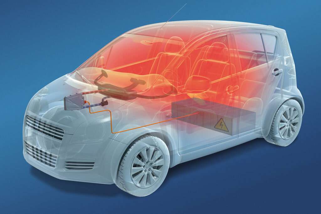
Battery cooling
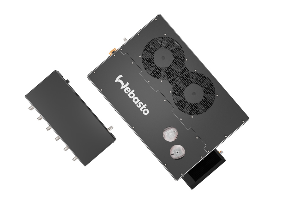
(Courtesy of Webasto Group)
As liquid-based cooling for EV batteries becomes the technology of choice, Peter Donaldson explains the system options now available.
A fluid approach
Although there are other options for cooling EV batteries than using a liquid, it is rapidly taking over from forced-air cooling, as energy and power densities increase. It is emerging as the dominant technology, particularly as the use of integrated thermal management systems for the whole vehicle become more common.
Such systems incorporate heating as well as cooling, and move heat around to control the temperatures of many components as well as the battery and cabin. The use of heat pumps and the imminent adoption of immersion cooling demand even more sophistication and adaptability from them.
The principal sources of heat in a battery pack are the cells, although the busbars that connect the cells and modules together can also get very hot. That heating is mainly ohmic in nature, resulting from resistance to the flow of current through the conductors. The cell tabs and connection points in the busbar system can therefore become hotspots.
The electrochemical processes inside the cells also generate heat, although in normal operation it is a relatively small amount. In a thermal runaway, however, they can generate a lot more, and very quickly, and can also release volatile chemicals from the electrolyte along with oxygen. Rapid, reliable detection and a quick response from the cooling system are therefore essential.

A typical cylindrical cell in the 21700 format, for example, has a power dissipation of around 5% when operating at low load, but can exceed that figure considerably at higher loads, according to an expert in battery and cooling systems. A 100 kWh battery pack could generate around 5 kW of heat, so only an efficient liquid-cooling system can remove that much from the cells quickly enough to keep them at a stable temperature in their optimum range, the expert says.
Abnormal events such as thermal runaways are a major safety issue for high-energy battery packs, and several specialists stress that safety is the most critical consideration in the design of an EV battery cooling or thermal management system. In the view of one expert in thermal interface materials (TIMs), initially too little attention was paid to safety in the pursuit of headline grabbing performance, an approach that has contributed to some high profile accidents and incidents.
WEG and alternatives
Typically, battery liquid-cooling systems rely on the familiar water ethylene glycol (WEG) mixtures used in IC engined vehicles. There are alternatives, however, including dielectric fluids for immersion cooling and even fluids containing highly thermally conductive particulates developed for computer servers.
What’s more, integrated cooling systems tend to require the movement of heat between different working fluids, and of necessity incorporate heat pumps that reverse the natural hot-to-cold thermodynamic flow. Engineers must therefore make the right choices for every vehicle, in what is a field of growing complexity.
The challenges faced in engineering these systems range from maximising the overall energy efficiency, cost effectiveness, responsiveness, robustness, reliability and ease of maintenance, to more detailed considerations such as the ability to make increasingly large cold plates. In integrated systems, it is also important to ensure there is enough capacity to keep occupants and the battery comfortable, for example.
One expert in the design and manufacture of electrified powertrain components and systems points out that this can be a tough balancing act, explaining that if you simply took the peak requirement for every component in the system and added them together you would end up with an over specified and thus expensive system.
With integrated systems, a further challenge is matching the different temperature requirements of different components, particularly if the battery needs heating while other components need cooling, for example.
Lithium-ion batteries perform best and live longest when kept at a comfortable temperature of between 20 and 25 C, which is relatively straightforward in temperate climates but far more difficult in regions of the world that experience extremes of temperature. While a given climate is usually fairly predictable and therefore tends not to demand a rapid response from the cooling system, normal operations such as rapid charging and emergencies such as the onset of thermal runaway do require the system to provide powerful cooling very quickly.
Not only must the cooling medium be able to remove heat from battery cells and the pack as a whole, the heat must be able to flow from the cells into the liquid as quickly as possible. That means the heat path must be as short as is practical, and demands intelligent use of the right TIMs.
Batteries are not actually difficult to cool, one expert at a specialist cooling company says, because their heat density is generally low, although the cost of cold plates and supporting materials including TIMs is an important consideration. However, minimising temperature gradients inside cells – more of an issue for core battery technologies than the cooling systems themselves – makes it likely that how a cooling circuit is designed will become increasingly important.
Furthermore, as the industry moves towards faster charging, even better temperature management will be needed. The charging rate has to be limited when batteries are too cold or too warm, and might have to be paused to let the battery cool if it heats up to 60 C or more.
Our powertrain components and systems expert emphasises the challenge of maintaining consistent temperatures across the pack, rather than any particular temperature point, to eliminate hotspots and temperature gradients, and to do that in an energy efficient manner. He stresses the importance of not allowing the thermal management system to become an excessive consumer of power in the vehicle, and of balancing consistency and energy consumption against cost.
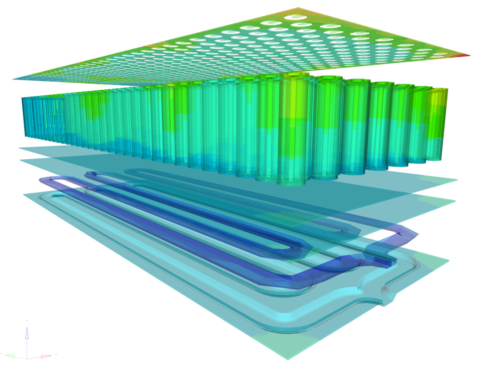
(Courtesy of Altair)
Simulating thermal behaviour
Thermal inertia – how slowly the temperature of a battery pack approaches that of its surroundings – is a critical factor to bear in mind when developing a cooling system with the required responsiveness. That depends on factors such as its size, shape, absorptivity, specific heat and thermal conductivity.
Although a modern battery management system will have a well placed set of temperature sensors and plenty of computing power to assess what is happening in the battery, thermal inertia sets the physical limits on which it has to work. Understanding the impact of thermal inertia, and developing designs that optimise it, is high on the list of challenges that engineers concerned with battery cooling in particular and EV thermal management more broadly must face.
A simulation specialist who helped with the research for this article says a digital assessment of the problem is a valuable step to take before committing to building physical hardware. The proposed system must be modelled as accurately as possible in software, to give the confidence that the prototype systems will respond as expected when they begin real-world testing. A colleague of his adds that as development progresses, the hardware and its virtual surrogate become complementary, each helping to ‘educate’ the other.
Eventually, it is likely that a virtual model will be good enough to act as the basis for a new battery and cooling system design. The colleague drew a parallel with the world of vehicle crash testing, where so-called zero-zero prototype testing has come to be accepted, because authorities are confident in engineers’ ability to predict the behaviour of vehicle structures in crashes. He cautions, however, that battery thermal simulation involves a lot of complex multi-physics work before it reaches that stage.
Before that level of confidence is reached, the first specialist notes, it is possible to change parameters in the virtual model and obtain good enough trend information to direct the development of hardware.

Digging into responsiveness a little further, there are several determinants of how quickly a cooling system can react effectively to a change in battery temperature. Another company with extensive cooling system and EV expertise points to the size of the battery packs, the total amount of heat in the system and requirements for uniformity of heat and temperature distribution – factors that have to be balanced against others such as the cooling system’s power consumption, cost, safety, reliability and service life.
In liquid-cooling systems, the mass of the fluid in the reservoir will help keep the temperature stable thanks to its heat capacity, which provides some extra time for the system to respond. In systems that rely on cooling from the phase change in a refrigerant, the position of the expansion valve can also be an important contributor to a quick response, a specialist in this technology notes.
The performance of coolant-flow control valves is also important to responsiveness, a specialist in electromagnetic solutions emphasises, and modern devices can easily meet the needs of EV thermal management systems in this respect. The technology enables response times as short as 200 ms, says the company – although opening in less than a second is normally adequate for EV coolant valves – while low hysteresis and a flat force/stroke curve contribute to accurate and repeatable control.
This specialist’s devices also use latching technology that allows the valves to hold position without needing a constant current, saving energy in battery-operated applications. With a typical operating voltage of 12-24 VDC and up to 2.5 A current draw, they permit flow rates up to 0.5 litres/second, coolant temperatures up to 110 C and circuit pressures up to 500 kPa.
Our expert in battery and cooling system design says the heat capacity of the working fluid, and hydraulic parameters such as flow velocities, are very important. He adds that a homogeneous temperature distribution across all the battery modules and cells is a very demanding requirement that calls for intensive optimisation of the flow geometries, noting that his company strives to keep the temperature in each cooling channel of a system within 1 C of the target value.
The heat capacity of the working fluid is one area in which liquid-cooling systems win out over those relying on air, our simulation specialist notes, with the speed of response coming from the greater capacity to absorb heat for a given mass flow rate.
Another key factor in responsiveness, the powertrain specialist says, is the quality of the thermal interface. This determines how effectively the heat generating components can be coupled to the components in the system that carry the heat away.
(Courtesy of AOK Technologies)
Minimising thermal resistance
The TIM specialist emphasises that this is all about minimising thermal resistance through the right combination of the physical distance that the heat has to cross and the gap-filling material that eliminates air between the surfaces, air being an effective insulator.
Gap-filling TIMs are rated by their thermal conductivity, which is a measure of how much power moves through a distance due to a temperature difference, and is often expressed in terms of Watts per metre per Kelvin (W/m-K).
TIMs with a high thermal conductivity are expensive, so it is generally more cost-effective to choose a small gap with a filler of more modest conductivity if possible. For example, a 10 mm gap filled by a 10 W/m-K material would, all else being equal, have the same thermal resistance as a 1 mm gap filled by a 1 W/m-K material. Surface area is also important here, he adds, with larger areas providing more opportunity for the heat to spread out, lowering thermal resistance.
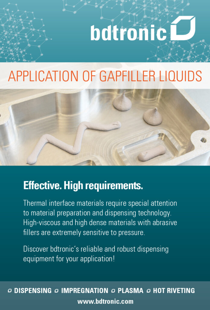
While it is common to transfer cell heat to the bottom of the module using a gap-filling TIM, it can also be useful to provide a thermal connection to the module’s sides, another TIM specialist says. That often means filling in large areas and thin gaps during manufacture, a challenge that has led the company to develop an ultra-low viscosity gap filler that it says “flows like water”, finding its own level and filling the entire space.
The company describes the filler as a two-component system with a viscosity of less than 5.0 millipascal seconds (mPa.s), a thermal conductivity of 1.8 W/m-K and an electrical insulation rating of 15 kV/mm. Silicone-based, it remains soft to accommodate the vibration and thermal expansion of other components.
Cell design also has a major impact on how quickly heat can get into and out of the pack, with cylindrical, prismatic and pouch cells all presenting different challenges. In principle, the larger the surface area of the cell in relation to its volume, the easier it is for heat to move in and out. As an illustration, a prismatic cell is a slim rectangular box, so it has eight times the surface area available for cooling as a cylindrical cell of comparable capacity, one of our experts explains.
Other differences in cooling behaviour can be associated with cell performance, our first TIM specialist adds, as high-performance or high energy cells tend to generate less heat than others. However, the cooling system must react even more quickly to changes in their temperature to keep them within their optimum range.
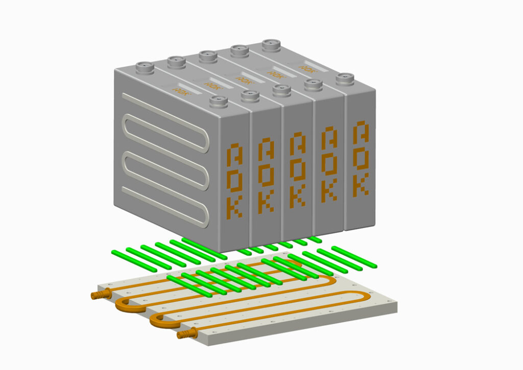
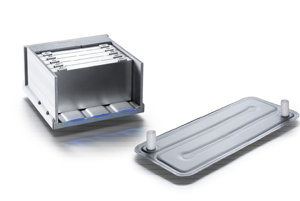
Packs consisting of modules with large numbers of small cylindrical cells, for example, are often cooled by fluid channels snaking between the rows of cells, with an inlet at one end of the module and an outlet at the other. That is not considered a good way of achieving even temperatures though, as the coolant picks up heat on the journey from one end of the cell to the other, creating an unwanted thermal gradient and presenting the risk of a short-circuit and a consequent thermal runaway in the event of a leak.

That has led to some battery pack developers to use alternative arrangements of cylindrical cells in modules. One way is to secure them in carriers that hold them at the top and bottom, with air gaps between cells to reduce the risk of thermal runaway, along with a cooling plate underneath that is thermally coupled by a thin layer of TIM, which also provides extra electrical isolation.
In designing an EV cooling system, whether it is to be dedicated to the batteries or serve as part of a whole vehicle thermal management system, characterising the cells to be used is one of the most critical considerations, our first expert emphasises. This involves a large set of measurements, detailed electrochemical analyses and intensive laboratory testing under conditions that closely match the intended use-cases.
(Courtesy of Webasto)
Heat pump options
This expert notes that while each battery and its cooling system is designed to meet the requirements of the intended application, requirements drawn up by customers are often incomplete and must be supplemented with the design team’s experience. With so many design criteria, multiple standards and use-cases, a great deal of care is needed at the design stage, particularly when matching the safety concept to the intended application and operating conditions.
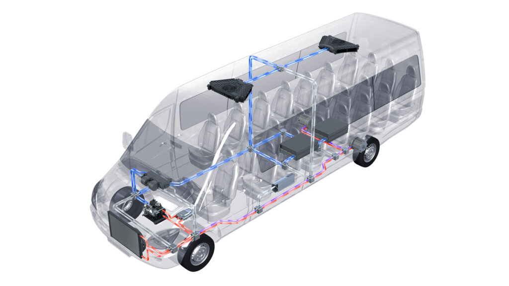
A battery pack and thermal management system developer we consulted emphasises that focusing on cooling (and heating) the battery alone is not the most efficient solution overall. The company has therefore integrated battery cooling and heating into its overall vehicle thermal management system, incorporating heat pump (HP) and refrigerant technology in a primary loop, and a secondary WEG loop for the battery and other vehicle systems.
As a HP can move heat from hot areas to cooler ones, and vice versa, for less expenditure of energy than say ‘brute force’ electric resistive heating, they are useful for saving energy overall. However, resistive heaters still have to be integrated for use in very low temperatures.
The above developer makes an HP based unit that can operate as a self contained battery thermal management module or as part of a vehicle-wide system. Consisting of a compressor, refrigerant, valving, a plate-type heat exchanger and control logic, the unit exerts full and continuous control over the compressor and the proportional electronic expansion valves.
In this way, it regulates the mass flow of the refrigerant passing through the plate heat exchanger, through the other circuit of which flows the WEG mixture that regulates the temperature of the battery and, in an integrated system, other vehicle subsystems. This secondary loop, the developer says, is coolant-agnostic and can easily be adapted to dielectric fluids, for example.
It can also be connected to a separate valve block that allows fluid flow to be directed to individual battery packs and other components, enabling the system to prioritise any component that needs cooling or heating.
A senior engineer from this developer says the term ‘battery thermal management system’ means different things to different people, even when referring to active systems. For example, such a system could feed water chilled to a set temperature, such as 15 C, with a constant flow rate into a battery pack. A basic system like that might be relatively cheap to make, he says, but it would use a lot of energy and would not control the battery’s temperature very accurately, resulting in a shortened service life.
It would also miss the opportunity to use waste heat from the battery elsewhere to offset the vehicle’s overall energy consumption. The engineer comments that although today’s EV fleets are not large enough to put stress on electricity grids, at some point energy efficiency standards for EVs will become essential.
(Courtesy of Croda)
Coolant selection factors
When it comes to selecting liquid coolants themselves, several factors must be taken into account. Technically, the most important properties are the lowest feasible electrical conductivity, and low and stable viscosity behaviour in all temperature ranges. Environmental compatibility is another key consideration, measures of which include the Global Warming Potential, CO2 balance and physiological safety in the event of an accident. Inevitably, the cost must also be low enough to allow competitive systems to be developed. One specialist we consulted says his company specifies and evaluates about two dozen properties for the coolants it recommends for its systems.
WEG remains the dominant coolant, because of the excellent heat transfer properties of water, and because it is cheap, easy to pump and ubiquitous. It is made from a mixture of distilled or de-ionised water (which is the actual coolant) and ethylene glycol to lower its freezing point and raise its boiling point, with additives to inhibit corrosion. Ethylene glycol is toxic, however, and industry is increasingly offering alternatives based on propylene glycol, which is already deemed safe for use in the food industry.
While battery and cooling system developers endeavour to make their products agnostic as regards fluids, this is complicated by the additives used in both WEG and propylene glycol-based coolants. These additives are the main differences used to define coolant products, including inorganic acid technology, organic acid technology and hybrid organic acid technology types.
As these fluids were developed for IC engines, it is natural to consider whether there are better alternatives for EVs. One important direction here is the use of fluids that do not conduct electricity and can therefore be used in direct contact with cells, transferring heat from and to the cell over its entire outer surface area.
Designed to adapt to a broad range of geometries, this cooler beneath the prismatic cells in this image is claimed not to require thermal gap fillers, but appears to be compatible with them
(Courtesy of Miba)
Dielectric fluid development

One major category of such dielectric fluids is silicone oils. Long-established in cooling high-voltage transformers in domestic and industrial power distribution grids, they have also been adopted as immersion cooling fluids to transfer heat away from electronic components in data centres, and have been investigated for EV battery cooling.
Our EV powertrain specialist says his company has been involved in extensive investigations into the use of silicone oils, reporting though that their generally high viscosity makes them much harder to pump around a cooling circuit than a conventional fluid such as a WEG mixture. A cooling system using it would therefore probably need more power, all other things being equal.
Some of them can also exhibit unusual fluidic behaviours, he adds. For example, one that the company tested turned out to have non-Newtonian properties, causing it to behave rather like British custard, thickening in response to a pumping force.
Such issues are likely to have contributed to uncertainty surrounding the future of immersion cooling. One niche chemicals company tells us that while battery manufacturers’ enthusiasm for it has waxed and waned over the past five years or so, it believes it will be widely adopted soon.
Another group of materials that make good bases for dielectric cooling fluids are esters. A spokesperson for a supplier of esters used as additives and base oils by major lubricant formulators says they can be engineered for low viscosities to ease pumping, along with high flash points that make them less volatile and therefore safer than alternative synthetic base oils such as polyalphaolefi ns (PAO) and Group III oils. Esters can also offer high thermal conductivity, higher than PAO2, PAO4 and Group III oils.
Contrary to a widespread misconception, esters also offer good stability, with higher breakdown voltages and longer oxidation induction times than hydrocarbon-based oils, the spokesperson says.
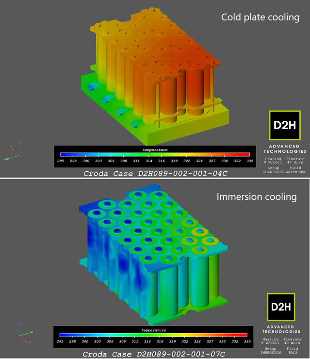
The company used an ester based fluid in a recent comparison of alternative dielectric fluids and cold-plate and immersion cooling, which involved simulations, CFD analyses and hardware models of battery modules composed of cylindrical cells. The combination of ester-based fluid and immersion cooling exhibited more efficient heat transfer, with fewer hotspots and more stable characteristics.
The company is about to launch a new fluid that it regards as a first generation product, as a market tester to elicit feedback from industry in what the spokesperson hopes will generate fruitful conversations between chemists and battery engineers.
Some of the more exotic fluids used in cooling high-end computer systems such as servers are beginning to incorporate particulate matter such as graphene to improve their heat transfer properties. One expert with experience in this area says that, as well as the properties of the material, particle shape, size and the way they contact each other are important determinants of how much heat transfer capability they add to the fluid.
These factors also influence the wear that such particles might cause to pumps and valves in the system, for example, which is potentially a big issue in vehicles intended for long service lives with a minimum of maintenance.
High on the list of important criteria for any new or improved working fluid is worldwide availability in mass-production quantities at low cost, which the EV and battery industries can only achieve through partnerships with large companies in the chemicals industry, our expert in battery and cooling system design says. In terms of technical properties, homogeneous viscosity, higher thermal conductivity and good processability for production will continue to be the strategic development directions, he adds.
(Courtesy of Webasto)
Fluid-agnostic systems
Increased adoption of immersion cooling and more diverse and advanced heat transfer fluids will make life more complex for cooling and thermal management providers who need to engineer their systems to be as agnostic as possible when it comes to fluids.
The developer we consulted has worked to get ahead of the curve here. They say they have focused on material compatibility and adaptable control parameters that enable its new system to accommodate the different heat transfer capacities and fl ow characteristics of various fluids in the secondary cooling loop, which can be both cooled and heated by the HPbased primary loop.
The company has taken a similarly flexible approach to this primary loop with its self-contained compressor and plate heat exchanger module. As the components for this module are sourced from the market rather than developed in-house, it is fairly straightforward to replace it with a system that uses a different refrigerant without disturbing the secondary loop.
A further benefit of this approach, his colleague says, is that it minimises the quantity of refrigerant in the vehicle and therefore the potential for leakage, which is very significant in large

Future directions
Looking further ahead, the EV battery industry will have to come to grips with new cell technologies with different chemical compositions, including those with solid electrolytes. These, says our expert in battery and cooling system design, will require extended thermal management because of higher operating temperatures, while other future concepts such as cells with super-porous separators will need even faster responses from cooling systems.
Advanced phase-change materials, particularly those that absorb energy in solid-to-liquid changes, are likely to be needed to cope with extreme conditions. However, others that use mechanisms such as ablation or becoming volatile can absorb even more heat energy and are therefore good candidates for slowing thermal runaways, enabling the main cooling system to mitigate the risk of runaway propagation from cell to cell.
It is clear that the evolution of thermal management for EVs in general and battery cooling in particular is accelerating.
Acknowledgements
The author would like to thank Angelo Hrenczuk at AOK Technologies, Dr Richard Boyd and Dr Royston Jones at Altair, Ryan Maughan at Avid Technology, Sukhvinder Kang at Boyd Corporation, Kyle Thompson at Croda, Wolfgang Hoefer at Kerafol, Dr Laszlo Katona at Kreisel Electric, Janella VanRens at TLX Technologies and Marian Paul Culik and Charles Byrd at Webasto for their help with researching this article.
ONLINE PARTNERS
