


Electric motors for aircraft
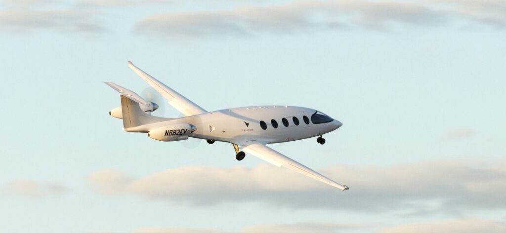
(Courtesy of Eviation)
In the line of flight
Developments in motors for e-aircraft are becoming intertwined with issues of energy storage and certification. Nick Flaherty reports
There are many different designs for motors being developed for a variety of electric aircraft platforms, from vertical take-off air taxis to 100-seaters with a flying time of an hour or so for regional flights. This is leading to a range of design architectures to reach and exceed the 13 kW/kg power density needed for flight.
However, the challenge remains for long-range, large-capacity aircraft. The challenge is not so much the motor, more the energy storage and the certification, says motor supplier MagniX.
“With hydrogen, for example, it’s more a question of certification than the technology, it’s about how to build the technology in a way that is appropriate for certification,” says Riona Armesmith, CTO at MagniX. “It’s a lot of work to certify the system, which means a lot of cost.
MagniX is working on motor designs targeting 350 and 650 kW of power. “These are representative of the size of aircraft we are working with, whether single or twin-engine with up to 19 seats, and that’s driven by the energy storage available,” she says.
Motor makers are working to increase the efficiency of the systems, increasing the power of the magnets, reducing the weight of the rotors and stators and using new materials such as carbon fibre to reduce the weight. All this delivers more power with less weight, but these new designs require more detailed certification.
“If you can increase the efficiency you reduce the kilowatts you need and the amount of energy storage,” says Armesmith. “Because of that, we are moving to integrated powertrains.”
“Small gas turbines with hydrogen are at most 30% efficient, fuel cells offer potential efficiency improvements, and low-temperature PEM fuel cells are 50% efficient,” she says. “But when you add in a lot of the extras, that efficiency has yet to be proven as you need power to run the compressor, and that takes energy away from the efficiency of the system.”
Motor technology
Armesmith adds, “The core of the motor and the electronics were developed 5 years ago, and since then it has been all about proving the development, working with the regulator and proving the compliance. The next stage will be writing the test plans and getting them approved. At the moment, nothing is certified for a passenger commercial aircraft so that is the vast majority of what we do.
“We are not chasing the next kilo of weight, we have the motor and electronics at the point where we are happy with it, so it’s about getting the system into service. The certification hurdle is huge, and you can’t be changing the design every 3 months. Aerospace is a very different environment to any other industry, and that really makes it more conservative.”
Other suppliers share that view. Arnold for example is working on r&d and design of the various motor technologies, from rotors and stators to sleevings. Its aerospace experience means it knows what is likely to be approved, making sure it is possible to manufacture the designs, and that the required strength of magnet exists.
Arnold has at least one project moving to the next phase, with orders, moving in the direction of approval. However, for rotor manufacturing it has not yet able been able to put the carbon fibre sleeving through the FAA certification process, and these are integral to the rotor assembly. Customers then develop their own stators and present the entire motor system for approval.
While Inconel or stainless steel have been used for years for rotors and stators, carbon fibre is lighter and has lower inductive losses so electric aircraft have every incentive to adopt the technology. Once the technology is approved for smaller electric aircraft then the larger companies are more likely to look at it, says Arnold.
Some are also using Arnold’s non-grain oriented silicon thin steel material for the lamination of the stators, to reduce weight and reduce eddy current losses with thinner layers to achieve the same effect as thicker steel.
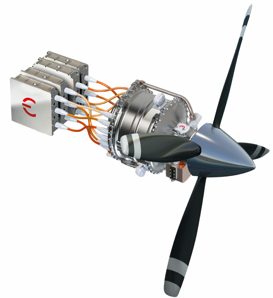
(Courtesy of MagniX)
Motors
“One of the great impediments to motors in aerospace is the power density and continuous power output, rather than the duty cycle,” says David Sercombe, project lead for the 350 and 650 motor programmes at MagniX. “The motor is then a primary structure, or it should be if you are to save weight.
“So the development involves materials and effective motor cooling, and that’s where a lot of our IP has been developed. Then come the structure, bearings and mounts that make a motor suitable for a long life in an aircraft.
The company is working with Eviation on Alice, a ground-up design for a nine-seater electric aircraft with a range of 250 nautical miles using two 700 kW motors. “The first step is to get the technical balance right. The next is taking that through flight trials and certification,” Sercombe says.
“We have flown on five platforms, which gives direct experience of how the motor performs in the air when it interacts with all the systems and going back through the inverter and the controllers. We couple that with R33 [an FAA method of compliance to support certification of advanced flight controls] for a path to certification. Then it is a case of looking at the endurance, the interaction with a series of propellers, and what novel faults might occur.”
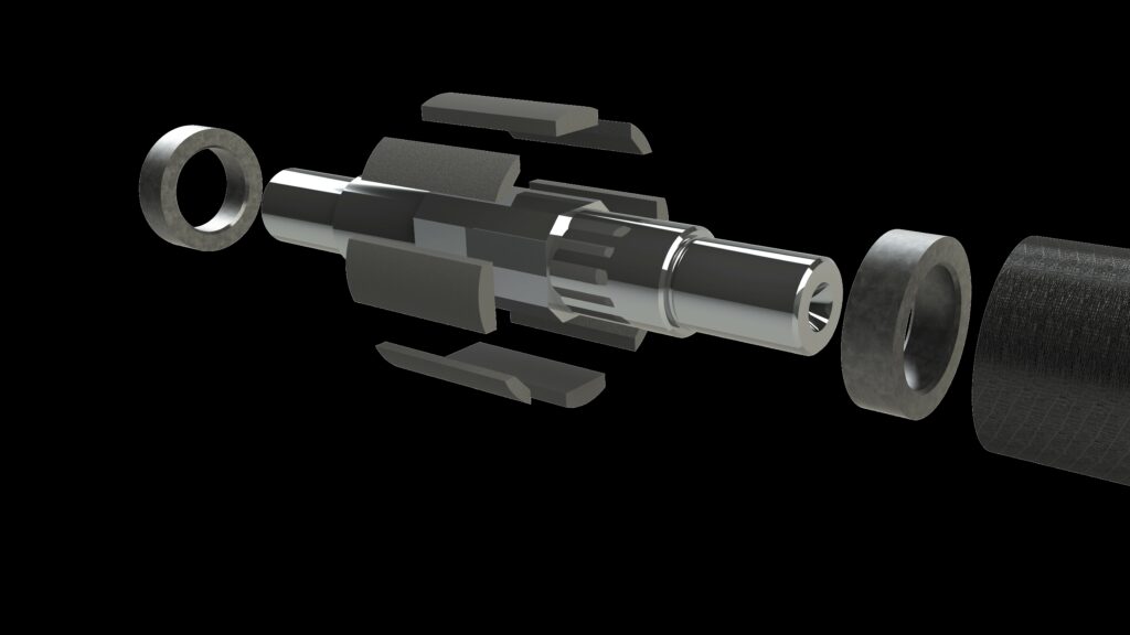
(Courtesy of MagniX)
Novel faults
“One thing is to have dual or quad-style systems with multiple segments so that faults can be isolated,” Sercombe says. “This is important, as in most applications you can glide or autorotate, but the ability to still produce power is desirable.
“At the same time, we learn from the failure modes in other industries, so we can continue with as much power as possible with open and short-circuits and all the things that can happen in an electrical system. It comes back to understanding the system in context, which might be the motor and inverter and cooling; the integration of the motor and the controller is really important as well.”
Certification also covers the development of software for the motor controller and the rest of the powertrain, which can be difficult if the motor is developed in isolation as a single component. Instead there is a shift to developing the motor as part of the whole powertrain so that elements of the motor can be optimised with the inverter and the energy source. Developing the software to control these elements is also a key challenge to ensure that the software can be certified as safe.
“The means of developing the software for the controller has to be according to a very specific set of plans for performance and safety,” Sercombe says. “This means you need an oversight and an insight into every element of the system rather than optimising the motor on its own.
“There are very interesting things on the horizon, such as the ability to have an influence over developing an energy storage system that operates at altitude.
“We are looking at type certificates in 2025 or 2026, but that entails working with our customers and integrators as there are a number of different permutations for the motors. We have a number of projects that are public, and the initial applications for certification are fixed-wing retrofits such as the 650 kW motor with the Beaver, then we will see what comes next.
Another supplier, Calnetix, has been developing electric machine and corresponding drive technologies for different aerospace applications. These include electric propulsion, power generation for hybrid electric aircraft, and starter/generator for auxiliary power units (APU).
“Calnetix’s high-speed technology minimizes the torque required and, consequently, reduces the size and weight of the electrical machine for equivalent output power,” says Co Huynh, co-founder and Business Unit Leader for Aerospace at Calnetix Technologies
“Further weight optimisation of the design is achieved by using the latest electrical and magnetic materials and implementing efficient thermal management configurations customized for each application. Calnetix has a unique suite of motor, bearing and drive technologies that optimize high-speed system for power density and efficiency,” he says.
The company has developed a motor that is rated at 100 kW and weighs 7.7 kg in a 2.3 litre volume, which is equivalent to a machine power density of 13 kW/kg and 43 kW/litre. This was achieved by optimising the electromagnetic design, including the magnetisation topologies and optimising the magnetic circuit, as well as the machine’s L/D (length over diameter) aspect ratio.
The design process also looked closely at the selection of materials, including the grade of magnets, the stator laminations and their thickness, the magnet retention sleeve and other materials to achieve the target power density of 13 kW/kg.
“When efficiency and weight are primary concerns, a machine with a permanent magnet [PM] rotor is superior in most applications,” Co Huynh says. “Some other advantages of using PM motors include zero excitation power, efficiency of 95% or higher, smooth rotor, large air gap, high resistivity and very low permeability of the rotor, and reduced inverter size and losses.”
Venky Krishnan, executive vice-president and business unit leader for Calnetix, says, “From starting with a few 100 kW, 50,000 rpm motors, we have developed multi-megawatt machines as well as mission-critical applications in the International Space Station.
“There have been recent advances in magnet strength and temperature capabilities, as well as improvements in the capabilities of switching devices, such as IGBTs and SiC devices,” he adds.
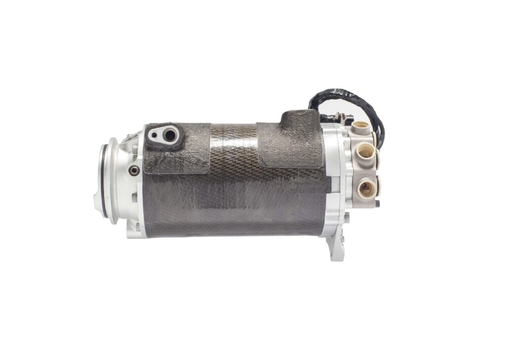
(Courtesy of Calnetix)
Magnets
A key issue of course is the magnets used in the motor design. The material they’re made from, whether a samarium cobalt alloy or neodymium, determines how much magnetic field can be induced when magnetised to create a permanent magnet. This then determines the magnetic field that the magnet can produce for a given weight, which determines the size and performance of the motor.
Arnold says it has the world’s strongest samarium cobalt magnet, the Recoma 35e, which has a flux density of more than 250 kJ/m3.
The choice of magnet material is based on a number of factors, although generally samarium cobalt is used where there are the highest temperature variations, and this is usually with airframe designs with one or two engines. If there are lots of smaller motors on an aircraft such as an air taxi then neodymium magnets are more often used.
Design
Researchers at MIT in the US have developed a 1 MW (1300 bhp), air-cooled, outer-rotor, Halbach array permanent magnet motor with a specific power of 17 kW/kg for aircraft propulsion as part of a contract with NASA. Experiments have validated the highest risk elements of the design, including stator core loss, structural stability, winding insulation and permanent magnet field strength.
Two manufacturing processes were developed for the stator cores using a combination of iron, cobalt and vanadium and compared through core loss and B-H curve measurements. A conventional lamination bonding process increases core losses by 20% so the researchers have developed and tested a new approach to modelling Halbach array rotors. The resulting modular single-phase winding pattern improved the robustness of the motor enabled single-phase inverter drives.
The design is being tested on two prototype machines connected through a shaft at 12500 rpm, with one acting as a motor and the other as a generator. All the major components, such as the stator cores, rotors, and heat exchangers, have been successfully manufactured. Remaining items such as machining the superstructure and winding the stator cores are in progress.
During the manufacturing process of the 1 MW demonstrator, the highest risk aspects of the design have been validated through stator core loss experiments, winding and insulation tests, rotor spin-pit testing at full operational speed and temperature, and rotor magnetic field measurements. The experiments show that the demonstrator will meet the design specifications and achieve full power.
The motor winding consists of 10 independent three-phase pole pairs. Modular winding schemes are increasing in popularity for electric machines designed for aviation owing to their better reliability than non-modular windings.
A pole pair contains three single-phase concentrated windings driven by three single-phase inverters, as single phase inverters have been shown to improve power density and robustness. Rectangular Type 8 (US AWG 24) Litz wire bundles are used to minimise the losses in the AC windings and maximise the copper fill factor.
Kapton tape and Nomex slot liners are placed between the phase windings in the slots and the end turns to improve phase-to-phase insulation. The slots are vacuum pressure impregnated (VPI) with an epoxy resin to improve thermal conductivity and electrical insulation. The resin has a favourable dynamic viscosity, improving the penetration of the varnish during the VPI process.
A mock-up of a single-pole-pair section of the stator was manufactured to verify the winding process. The stator section withstood the full operational voltage and current without insulation failure and successfully demonstrated the winding pattern, insulation and thermal sensor installation. The stator core loss estimate has been validated through experimental measurements on toroidal samples and full-size stator laminations and shows that this design reduces the losses in the stator by 20%.
One of the spin-outs of the project is a new technique for modelling the stator. This is a computational algorithm that is easy to use and adapt to different machine topologies rather than using finite element analysis (FEA).
This technique was used to design the rotor with four tangential segments per pole. This uses an approach called a Halbach array, a specific type of magnet shaping that can improve the performance of PM synchronous motors by creating a magnetic field that is stronger on one side of the array than the other. A magnetic field scan of the rotor closely matched the analytical model produced by the computational algorithm and FEA, showing that the demonstrator’s rated torque will meet the design specification.
Another 1 MW motor has been developed by Wright Electric. This was shown at the Paris Air Show in 2023 and will be tested at altitude in NASA Electric Aircraft Testbed (NEAT). The system can be used as a motor or generator, enabling it to be configured as a turbo-generator or auxiliary power unit for high-altitude power.
“Achieving 1 MW, specifically of shaft power, is an important step in achieving zero-emissions single-aisle flights of under 800 miles,” says Jeff Engler, founder and CEO of Wright Electric. “Commercial-class airplanes need megawatt-sized propulsion systems for a full passenger load at take-off. At the NEAT facility the motor will be tested at up to 40,000 ft.”
The plan is to use the motor for the Wright Spirit. This is based on the BAe 146 four-engine aircraft to carry up to 100 passengers on flights of up to an hour. The company has been proving system components including a high-efficiency, high power density inverter and a 2 MW motor.
The Joint Technical Assessment Phase (JTAP) on the propulsion system includes Honeywell for the turbo-generator and fuel cells as well as the use of test facilities, aircraft, along with infrastructure and batteries from Eaglepitcher Technologies.
The motor is currently being tested at 1.5 MW with a power of 2.25 MW for emergency take-offs to meet certification requirements. The plan is for flight testing with one all-electric engine this year, progressing to a full four-engine, zero-emissions flight of the 100-passenger, zero-emissions aircraft by 2026.
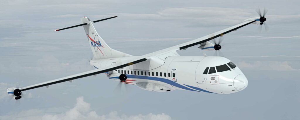
(Courtesy of NASA)
Motor acoustics
Greenjets is developing high-power motors for eVTOL and larger aircraft. It is using a mixture of additive manufacturing and traditional techniques for a motor design that can be scaled up.
The company is part of the InCEPTion project in the UK to develop an ultra-quiet motor by focusing on the design of the impeller blades of a turbine, to avoid audible frequencies from for eVTOL designs that people find annoying.
There are many metrics for quantifying noise, not just amplitude but also pitch and tonality that will have an impact on community acceptance. The level of sound measured in ‘A-weighted decibels’ (dBA) adjusts the decibel values to take account of the frequencies that the human ear is most sensitive to.
Conventional helicopters are the benchmark for comparison with eVTOL noise owing to their similarity in operation, and as such, predicted noise levels are often described as fractions of helicopter noise. A greater number of distributed motors reduces propeller diameter, decreasing tip speeds and improving the noise characteristics.
While some aircraft developers report a noise value, few describe the conditions under which this noise would be recorded, such as the distance to the microphone and flight mode. A small sample of eVTOL aircraft shows noise levels from 60 dBA on take-off and landing to 75 dBA in flight. In comparison, a four-seater Robinson R44 helicopter produces an overflight noise of about 80 dBA.
The strongest evidence of eVTOL noise performance comes from a collaboration between Joby and NASA, which used a field array of more than 50 microphones to record noise at numerous flight speeds and altitudes. In cruise at 500 m overhead, the research confirmed a noise level of 45 dBA, with take-off and landing noise calculated as 65 dBA from 100 m.
Another motor designer, Helix, has a unit called the SPX177, which provides 650 kW of continuous power but is aimed at automotive designs.
“We needed an architecture that minimises losses and the heat generated, especially at high speed, which meant quite a change in the way the motor was wound, since minimising resistance losses results in a very low inductance machine,” says Helix chief engineer and project leader Derek Jordanou-Bailey.
“The switching in the inverter can generate lots of noise and harmonics, which is more challenging with a low-inductance motor.”
“The SPX177 weighs just 41 kg, including the 13kg inverter,” he says. “It is a dual three-phase motor, so its current is shared across two inverters – a necessary approach to meet the phase current demands at ‘normal’ DC voltages at this extremely high power level.
“Six high-voltage cables connect the inverter to the motor, while an LV connector carries the various control signal.” The motor delivered over 700 kW peak on the test stand. “It could potentially deliver more, but we didn’t push it,” Jordanou-Bailey says.
NASA is working with GE Aviation and ManiX to support its Electric Powertrain Flight Demonstration (EPFD) to speed up the development of suitable electrified aircraft propulsion (EAP) technologies through ground and flight demonstrations.
The EPFD is part of NASA’s Integrated Aviation Systems Program, and aims to introduce EAP technologies to US aviation fleets no later than 2035, supporting short-range and regional commercial air travel, as well as single-aisle larger aircraft.
Over 5 years, the selected companies will conduct ground and flight test demonstrations of their EAP technologies for commercial aircraft transports. They will collaborate with other NASA projects on EAP development, flight test instrumentation and data analysis.
“GE Aviation and MagniX will perform integrated megawatt-class powertrain system ground and flight demonstrations to validate their concepts, and look at the benefits for future EAP aircraft configurations,” says Gaudy Bezos-O’Connor, EPFD project manager at NASA’s Langley Research Centre in Virginia.
“The demonstrations will identify and overcome technical barriers and integration risks. It will also help inform the development of standards and regulations for future EAP systems.
(Courtesy of ZeroAvia)
Hydrogen-powered flights
In the meantime, ZeroAvia in the UK has demonstrated its ZA600 hydrogen powertrain in flight. The company has a choice of motors from several suppliers for its test flights on a dual-engined Dornier 228 19-seater aircraft. The Dornier is powered by a prototype engine that combines a fuel cell, inverter and motor that generates 500-750 KW and paves the way for certification.
In 10 test flights during 2023, ZeroAvia tested different areas of performance using one fuel cell engine and one conventional. The test campaign saw the aircraft fly at 5000 ft, perform a 23-minute endurance test, operate in temperatures from just above freezing to almost 30 ºC, and reach the maximum allowable speed under a Permit to Fly issued by the CAA.
Critically, throughout all phases of testing, the fuel cell power generation and electric propulsion system that are the core components of the engine performed at or above expectations. The aim is to provide 300-mile range in a 9-19 seat electric aircraft by 2025, and up to 700-mile range in 40–80 seat aircraft by 2027.
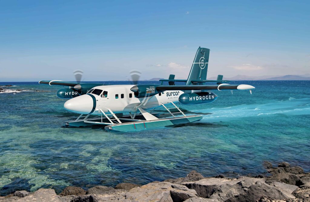
ZeroAvia has experimental certificates for its three prototype aircraft from the CAA in the UK and FAA in the US, and says it is on track for commercial operations in 2025. One customer, a new airline called Surcar, plans to use Twin Otter seaplanes retrofitted with the ZA600 powertrain for sightseeing tours.
Conclusion
Several electric aircraft projects are now flying with experimental certificates to prove the airworthiness and effectiveness of the motor technologies. They are showing the range of motor power, with multiple smaller motors at 350 kW and up to 2 MW systems for dual and even quad-engine platforms. The challenge is to certify the powertrains and the associated energy supply to deliver both urban mobility applications and regional flights of up to 500 km.
Click here to read the latest issue of E-Mobility Engineering.
ONLINE PARTNERS

