


Elaphe L1500 in-wheel motor
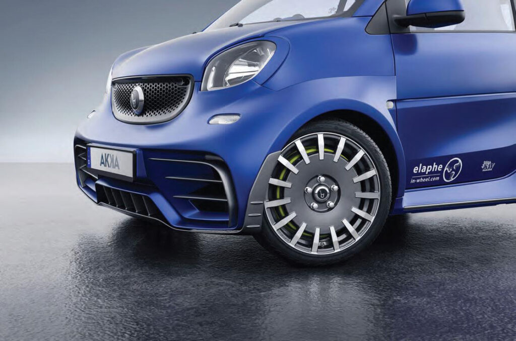
Applications for the L1500 in-wheel motor include Sportscars (above), pick-up trucks, SUVs and urban vehicles (right), among others
(Images courtesy of Elaphe Propulsion Technologies)
Fit for duty
The L1500 has been designed to enable it to be used in a wide range of OEM EVs and HEVs. Rory Jackson reports on how it was developed.
Slovenian company Elaphe is known in the e-mobility industry for its in-wheel propulsion technology, which is used in a range of automotive applications around the world. Established in 2006 by theoretical physicists Andrej Detela and Gorazd Lampic (now the CEO), its systems incorporate a host of patented and proprietary technologies across mechanics, electromagnetics and other disciplines.
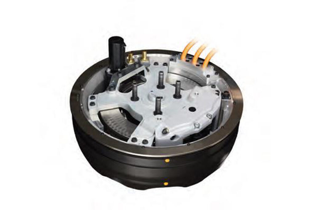
At the top of Elaphe’s in-wheel propulsion product range is the L1500, a radial flux, three-phase AC synchronous motor weighing 33.3 kg, with a radius of 23.2 cm (and therefore fitting a standard 19 in rim) and an axial length of 14.22 cm. At a nominal voltage input of 370 V, its maximum power output is 113.6 kW (at a speed of 1480 rpm), as well as a maximum tested torque of 1500 Nm.
Unveiled in 2019, the L1500’s design was based in the early stages of its development on the M700. The M700 was the first motor Elaphe fully validated according to existing automotive standards, and both motors have some architectural similarities.
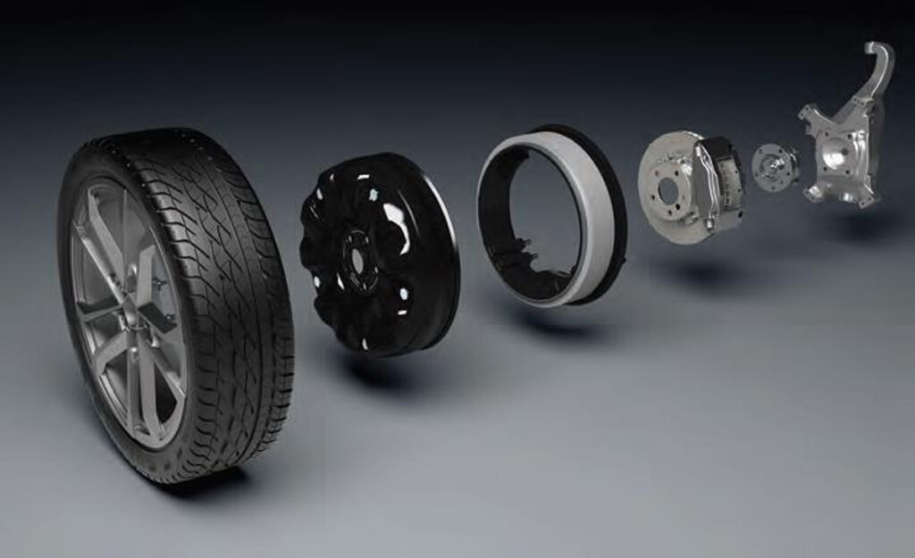
Elaphe integrates (from left to right) standard-issue tyres with 19 in rims, the L1500 housing (and rotor), its stator, standard automotive brakes and a standard bearing, to mount to the vehicle knuckle
Wherever possible, Elaphe has sought to minimise the L1500’s weight. As a result, the ‘active part’ of the motor – the electric machine with windings and magnets – takes up just 30% of the overall weight, giving it a torque density of 460 Nm/litre, compared with what the company cites as its nearest competitor at 390 Nm/ litre. It also has a torque-to-weight ratio of 100 Nm/kg; its competitors go up to 65 Nm/kg, Elaphe says.
The L1500 has 83 components, nearly 60% of which are standard supplier parts and the rest mostly casting or customised supplier solutions.
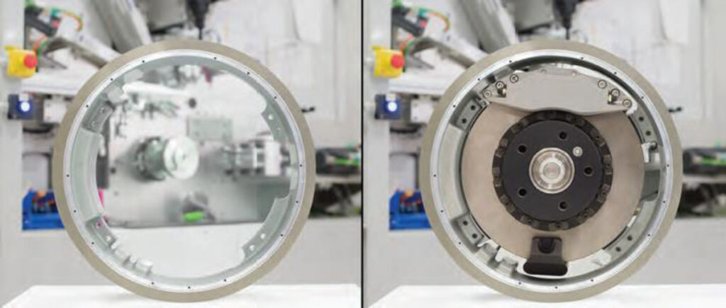
The system is configured as a directdrive outrunner (meaning it has an external rotor and an internal stator). The motor’s aluminium rotor case contains the yoke and permanent magnets, the case wraps around the stator, and is connected to the vehicle knuckle by a conventional automotive wheel hub bearing.
The stator ring is made from magnetic steel laminations. Its poles use a patented winding method developed in-house, and it attaches directly to the vehicle knuckle. A traditional friction brake, with a disc rotor and caliper, fits inside the stator ring and attaches to the hub, as in all cars these days.
Ease of integration and component logistics have also been strongly prioritised by Elaphe during its design of the L1500. As a result, all wheel integrations using the motor will also incorporate standard, off-the-shelf automotive bearings and braking systems (of which a range exists), including standardised brake rotors, calipers and electronic parking brakes.
The described assembly of rotor, stator, brakes and bearing transfers loads from the road (which will vary depending on vehicle weight, braking dynamics, cornering and ground roughness) directly to the vehicle knuckle via the bearing, protecting the electric motor components from such impact loads.
Elaphe integrates (from left to right) standard-issue tyres with 19 in rims, the L1500 housing (and rotor), its stator, standard automotive brakes and a standard bearing, to mount to the vehicle knuckle
Those parts are also kept as accessible as they would be in conventional road vehicles (and thus easily serviceable) thanks to the company’s approach to integration, in which the motor is mounted over the brake assembly, similarly to the rim and tyre.
As a result, each customer’s motor can be customised to a degree to modify the rotor and stator interfaces to accommodate their preferences in peripheral components such as the brakes, bearings and other internal parts.
“The L1500 motors are therefore simply inserted between the electric [or hybrid] vehicle’s hubs and rims, which makes use of the existing space within the wheel without needing to alter any suspension or steering packaging on the platform,” explains Elaphe’s CTO Gorazd Gotovac.
Within 5 minutes the L1500 can be integrated into or removed from a car wheel for routine maintenance, such as brake inspections and replacements.
In addition to being able to customise the in-wheel electric motor for carmakers’ preferred brake and bearing suppliers, the L1500’s performance and components can also be tailored to meet manufacturers’ application-specific requirements.
As Lampic says, “We wanted to bring what we feel is required for improving future OEM EV/HEV models. More specifically, we saw a gap in the market for high-performance distributed drives for electric CUVs and SUVs, sedans, pick-up trucks, people-movers and extremely low energy demand vehicles. Most of these segments have high growth potential, and they also benefit from a real four-wheel-drive capability with torque vectoring and brake blending in a compact package.”
Specifications
Permanent magnet, three-phase synchronous AC motor
In-wheel/direct drive
External rotor with surface-mounted magnets
Internal stator with pseudo-helical multiphase wave winding
Liquid-cooled (50:50 water-glycol mix)
Operating voltage range: 200-800 V
Maximum power output: 113.6 kW at 370 V DC
Continuous power output: 65.3 kW at 370 V DC
Continuous power output with field weakening: 83 kW at 370 V DCMaximum torque output: 1500 Nm
Continuous torque output: 650 Nm
Weight: 33.3 kg
Diameter: 464 mm (fits standard 19 in rims)
Axial length: 142.2 mm (hub-to-rim attachment is less)
Multiphysics structural design
To ensure each motor provides precise and reliable performance over its lifetime, regardless of differences between vehicle chassis and complementary parts, Elaphe has a rigorous set of design requirements, simulations and testing processes. This is vital, as the development of robust in-wheel electric motors encompasses a far broader set of targets than simply achieving the optimum magnetic fluxes, inductances and other typical electric motor parameters.
“What we did – in our capacities as physicists – was to analyse the electromagnetic, thermal, mechanical and control aspects of the motor simultaneously, from the outset of the L1500’s development. It’s what we call our ‘multiphysics’ approach,” says Lampic.

Elaphe uses an SUV test vehicle to simulate severe braking and cornering scenarios
“At each stage of this approach, we have worked on the basis of analytical equations that have afforded us an insight into holistically optimising our motors’ designs and dimensions, to meet a broad envelope of performance and environmental requirements as well as other evaluation criteria.”
As Lampic notes, every component in each L1500 must be designed for ‘multiphysics efficacy’, capable of handling many different kinds of thermal, structural and electrical loads.
Scalability of the company’s design processes has been critical for conceiving the structural architecture of each new L1500. Being Elaphe’s largest and most powerful in-wheel motor yet, the project represented new territory for everyone involved.
“Our insights and models for e-motor optimisation are part of our proprietary knowhow,” Lampic adds. “While there’s still some way to go in terms of common, smart standards for inwheel motor development, over the past 20 years we’ve created a set of internal standards based on our tools, methodologies and various industry best practices.”
The decision to create a set of internal standards for design concepts has also resulted in Elaphe building its own testing centre, which houses machinery to evaluate the endurance and durability of new prototype and customised motors. The equipment enables rapid iterations and confirmations of product designs, although the company also cooperates with various institutions around the world for impartial third-party validations and to complement its own efforts.
“In general, our testing strategy is based on three factors – testing based on OEM and international standards, then legislation, and lastly, internally identified tests based on design failure mode and effect analysis exercises, vehicle tests and simulations,” Lampic says.
“OEM and international standards in particular have been adapted to cover location-specific environmental and structural load requirements, which differ greatly for in-wheel motors compared with centrally mounted e-axles, as they are usually derived from structural and electrical components that reside in the wheel in ICE-powered cars.
“Those standards have also informed our requirements for e-motor and inverter-specifi c performance parameters, EMC, electrical safety, durability and cable routing. Analysis based on the ISO 26262 standard has also been useful.”
In-wheel motors are subject to far more impacts and stresses over their lifetime than any e-axle motor, as they are constantly in almost direct contact with the road. As a result, Elaphe’s development models encompass an extensive number of studies, simulations and tests, to iterate a motor that will withstand a broad spectrum of loads over its lifetime.
Some of those loads acting on the L1500 are internally generated. Examples of these are thermo-echanical stress due to excess heat from electromagnetic losses in the copper windings, steel laminations and permanent magnets, and frictional losses in the bearings and seals.
Excess preloading from manufacturing, introduced mostly during machining and casting, can also cause residual internal stresses to build up in motor designs before they are tested. To that end, Elaphe has used heat treatments to minimise these loads and their effects on structural components.
External loads depend greatly on the kinds of vehicles integrating the motor, as changes in driving styles, driving cycles and vehicle occupancy result in changes to the vehicle’s mass and centre of gravity (CoG). For example, e-motors on heavy commercial and off-roading vehicles will endure higher external loads owing to harsher interactions between tyre and the road.
Also, ground-induced or roadinduced loads consisting mainly of vibrations and bending moments can act on the e-motor via the tyre. These must instead be transmitted through the rim and bearing and into the knuckle (before continuing on to the vehicle chassis).
To accurately predict and assess the motor components’ structural integrity requirements in the face of especially harsh road-induced loads, Elaphe used an SUV to simulate severe braking and cornering scenarios. The tests investigated CoG acceleration and the external lateral loads on all four wheels – with particularly severe cornering (more than 1.1 g of lateral acceleration) producing roughly 14,000 N of force on one of the car’s right-hand tyres.
Additional simulations of external loads on the L1500, such as those coming from hitting potholes, curbs or other issues related with rough roads, were performed according to SAE standards including SAE J175 and J1981 on impact tests for wheels and tyres in road vehicles.
Although such studies and simulations might seem premature, identifying the many loads that act on in-wheel motors (and the resultant effects) were critical to defining the design targets for the L1500’s component architecture and optimisation.
Before iterating the key aspects of a new L1500’s design through CAD simulations, Elaphe first selects the key peripheral components (including the rim, brakes and bearings) in order to define how much space is left for the stator and rotor.
To flesh out the ideal design of the housings and motor interfaces, Elaphe’s technical specialists perform ‘topological optimisations’. These begin with a vague CAD approximation of each component with a target level of structural stiffness, then repeatedly exposes them to different load simulations, (including differing combinations and quantities of them), over several dozen iterations.
By running these load simulations in a generative design process (with a constant stiffness target and through a set of proprietary criteria functions), the numerical software can identify all the geometric qualities necessary for minimising structural stress across the metals of the stator and rotor (while also keeping it lightweight and taking manufacturing constraints into account where possible).
The designs yielded from topological optimisation are then run by an industrial designer, so that they can advise on precise guidelines and limitations regarding how the CAD drawings can be feasibly and accurately reproduced in the real world.
Having been filtered through the industrial designer’s guidelines, the stator and rotor designs are then evaluated (together with connected structural interfaces for a holistic motor simulation) using multiphysics finite element analysis (FEA) testing.
The FEA includes static simulations (that is, one-off impacts) of how stresses and deformations would be distributed across the motor under varying load speeds, the levels of and ways in which friction occurred between components and connections, and other properties of the design’s structural integrity.
Also, NVH (noise, vibration and harshness) simulations provide insight into a critical part of inertial load testing. The company has software scenarios (and dedicated test tracks, which would be used for road-proving the motor later on) for driving over potholes, brick roads, speed bumps, embedded rock paths and other surfaces to examine how the motor handles the repeated impacts and harmonic stresses of such use.
Following static testing, fatigue tests are performed to simulate the effects of multiple loads over the service life of the motor, and to see how many repeated loads the motor could take before its components’ finite elements begin showing signs of deterioration.
Elaphe’s approach to such testing is based on the ISO 16750-3:2007 standard for environmental conditions and testing for mechanical loads on electrical and electronic equipment.
After examining where the earliest deteriorations appear, the design loop is (where necessary) executed again from the start in order to optimise the chamfers, radii and other small shapes and details of the components before actual fabrication.
Bearings in mind
As mentioned, defining the optimal bearing was one of the earliest and most important tasks in the L1500’s development, in terms of defining the tolerances and optimal design qualities of its various components.
“The bearing is selected as a function of the wheel loads stemming from the vehicle’s weight, its CoG, wheelbase, track width and maximal lateral acceleration achieved during cornering. It also has to adhere to tilting stiffness conditions,” Gotovac says.
Lampic adds, “We invest resources in defi ning the brake, bearing, suspension, control and other requirements, building simulation models and characterisation procedures to determine whether a COTS or custom bearing can be used. That allows us to focus on our core competencies in stator and rotor design, and saves us quite a bit of overengineering.”
Approving a bearing for the L1500 requires a measure of special attention. Loads coming from the road apply significant forces – particularly bending moments – on the bearing, which lead to minor elastic deformations while the motor is operating.
While normal bearing deformations aren’t a major problem, excessive deformations in an in-wheel motor can cause deflections between the rotor and stator.
This changes the shape of the air gap, which causes vibrations as well as loss of efficiency owing to the increasing resistance to magnetic flux between windings and magnets where the gap widens, and decreasing flux resistance where it shrinks.
To minimise the effects on the air gap, the bearing must be able to sustain sufficient external loads to prevent them passing through to the rotor and stator. Elaphe has therefore developed a regime for validating the stiffness and durability of bearings before it will integrate them into the L1500 (or its other in-wheel motors).
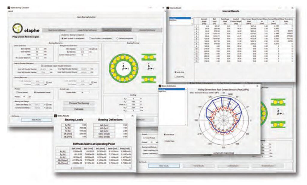
First, the stiffness of the customer’s preferred bearing is characterised using Elaphe’s in-house numerical analysis software.
For broader and closer accuracy of how the bearing will behave over its lifetime, Elaphe then conducts experiments using the Wheel Accelerated Life Test machine (WALT) at the Fraunhofer LBF Institute for Structural Durability and System Reliability in Darmstadt, Germany, with additional similar tests locally on dedicated deflection measurement benches.
WALT machines were originally developed to rapidly test and analyse how wheel components would resist damage over their lifetimes. As well as being useful for testing tyres and rims, they are also designed for studying bearings in a fast, repeatable and controlled manner, which is ideal for the L1500.
After ascertaining the stiffness of the bearing, deformation analysis of the air gap follows. This rests on putting the bearing and the motor through cornering, endurance and durability tests (in accordance with SAE standards J328/2016-03 and J328/2005-2) to see how it sustains loads (reducing their transmission to the rest of the motor), and whether contact in the air gap occurs at any point.
Thermal sensors are added to the bearing hub during these tests to measure any overheating. A thermal camera also records complementary data, and laser sensors measure axial and radial deformations of the rotor.
Once these tests confirm that the motor components undergo no damage, and experience no stator-rotor contact in the air gap (and that the bearing never overheats or reaches temperatures indicative of damage), the customer-preferred bearing can be integrated into the L1500.
“The combination of the maximum Hertzian contact stress and the strain corresponding to the maximum allowed air gap deviation yields a specific bearing requirement, called the ‘tilting stiffness’, which is typically between 7 and 10 kN/° and which also encompasses extreme cases,” Gotovac says.
“An OEM in collaboration with Elaphe can select their preferred bearing that fits within these parameters – and most existing OEMs and suppliers produce bearings that are suitable.”
Final assembly and tests
Once the L1500’s main components and their details are ironed out, holistic analysis of assembly-related loads are performed. These are issues that cannot be isolated to singular components or sections thereof.
For example, thermo-mechanical simulations are carried out to examine how the air gap between the rotor and stator might deform as a result of severe heat and shock. These simulations must show that the degree of deformation never exceeds a certain (undisclosed) value, thus ensuring no impact between the windings or permanent magnets can occur.
Once all the design choices are affirmed via CAD and FEA analysis, a prototype of the motor variant can be built and subjected to a range of tests on the company’s test benches to validate the accuracy of the simulations.
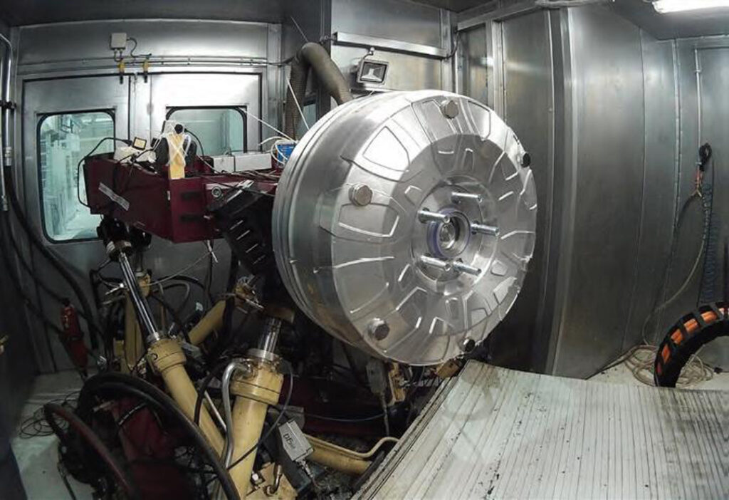
“Most of the world’s high-power electric motors are high-speed and medium- or low-torque systems, so most measurement equipment worldwide is designed for those characteristics,” Gotovac notes.
“For instance, even in a 200 kW test system it is unlikely that a 60 kW in-wheel motor could be tested at its rated or peak torque, because of how a supplier’s test benches are built and their corresponding torque-sensing limitations.
“That is why our measuring stations have been developed internally from scratch, using a combination of industry-standard hardware and software along with our own improvements, to fulfil in-wheel propulsion system requirements while staying compatible with most other systems.
“In parallel with the high-torque requirement, we’ve constructed them in a way that avoids resonant frequencies when testing motors at very high speeds.
“Combining those two aspects makes our measuring stations uniquely ‘universal’ in their ability to test motors of widely different types and characteristics, while complying with automotive standards.”
Tests on the L1500 include those for mechanical shocks. These consist of 18 shocks, each measuring 100 g (in force) as well as 60 more shocks of 50 g each.
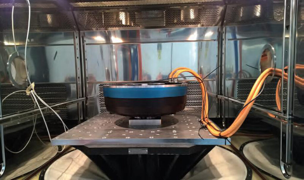
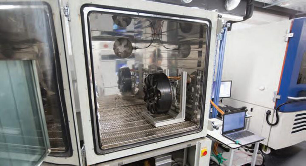
Random vibration endurance is also tested, by combining a shaker table and a thermal chamber to apply vibrations at up to 2000 Hz and 40 g in force in the horizontal, vertical and axial directions. As with the previous fatigue simulations, both tests are performed in accordance with ISO 16750-3:2007.
In addition to its in-house testing facilities, Elaphe also sometimes uses third-party testing facilities for more conventional or specialised tests, such as for vibration, shock, environmental IP rating and EMC.
Rotor
Given the importance of torque density to an in-wheel motor, Elaphe has built the L1500 with an outrunner configuration, with the rotor directly driving the wheel as it rotates.
“In our standard, publicly known solutions, we construct the rotor with surface-mounted permanent magnets, although we are familiar with other ways of designing and installing the magnets if the application or customer requires their use,” Gotovac says.
“The number of magnets we install varies but is quite high, usually exceeding 40 on the L1500. That keeps them small in size and has some very positive effects in terms of reducing eddy-current losses and their overall mass relative to the magnetic flux.”
Neodymium is used for the L1500’s permanent magnets, a material selection which has also been motivated by the need for high torque density. “The exact grade of neodymium in each L1500 depends on parameters related to cost optimisation and application-specific development, among others,” adds Gotovac. “For magnetic strength, there is always a compromise between the magnet grade and the physical air gap in the motor.”
As the CEO notes, Elaphe’s proprietary holistic motor optimisation algorithm takes into account (among other information) a wide range of magnet parameters as it evaluates an overall motor design.
“In the early years of developing our in-wheel motor technologies, we used mainly N40UH magnets [which have a maximum working temperature of 180 C] in our prototypes in order to ensure good thermal performance,” Gotovac recalls. “With more experience and our model accuracies optimised, we replaced the N40UH with N40SH, the latter being in the 150 C temperature class.”
The selection of an adhesive for bonding the permanent magnets in their slots is tested and validated in a similar way to the structure of the rotor and stator. Its endurance and durability are examined across temperature cycles, load cycles, humidity, shock and vibration to ensure the magnets will remain secured in all modes of use in a modern passenger car.
Stator multiphase wave winding
The L1500’s stator poles use a form of winding patented by Elaphe, in order to achieve performance improvements over alternative winding configurations, which for in-wheel applications were regarded as providing insufficient levels of torque, energy efficiency and cost-effectiveness.
For example, in lap winding, each continuous strand of conductor wire can be damaged as it is inserted into and twisted around the stator teeth. Furthermore, wrapping wire in this way creates significant overhangs of copper, with strands sticking out from stator teeth (owing to the high number of turns around them) or protruding as they cross from one tooth to the next.
As these overhangs lie outside the stator slots, they do not contribute to motor torque. They therefore mainly just increase electrical resistance and heat, causing losses in energy efficiency.
Many forms of wave winding also have overhangs that contribute to inefficiencies. Like hairpin stator windings, these can be bent into shapes that forcibly pack the copper back into the ferromagnetic core and minimise the degree of overhang outside of it. However, wire strands can suffer significant damage as a result.
Hairpin stators and similar configurations using discrete, short segments of copper conductor bars (rather than strands of wire, or ‘block coils’ cut from copper foil sheets) can be deformed as needed, to minimise overhangs and maximise the packing density in the stator slots without being damaged.
“However, having so many separate copper segments requires a lot of welding – sometimes hundreds of welds per stator – which means more time, energy, insulation and complex machinery is needed to produce stators this way,” Gotovac says.
“If you can use an uninterrupted, continuous wire instead of so many separate pieces, you don’t need so much insulation, and it’s more cost effective to manufacture. Our method means maybe only 24 welds or so are needed for each L1500 stator.”
Elaphe’s method is called ‘compact multiphase wave winding’. Its development originated in the early 2000s, with intended (and achieved) benefits including improvements in specific torque, energy efficiency, ease of assembly and ease of cooling relative to traditional coil-winding approaches.
As with hairpin stators, compact multiphase wave winding uses thick, pre-deformed ‘bands’ (essentially long, thin rods) of copper, rather than strands or thin sheet-cut tapers, for its conductors. The conductor bands can have a round or square cross-section, as well as a tangential shape to ‘u-bend’ around each stator tooth to the next, with at least one continuous band per phase of the motor (unlike the many separate bands used in hairpin stators).
“The exact length of each band is customised for the application to achieve the correct voltage balancing in each wire, and by extension the right speed and the torque for the motor, without any detrimental effects on current losses,” Gotovac adds.
Elaphe’s in-house winding machines are optimised to apply each subsequent phase of copper with the appropriate force to insert and compact the bands into the stator slots as deep as necessary for the desired packing density and uniformity, without scratching or breaking them.
Also, the bands’ overhangs are pre-formed in a ‘pseudo-helical’ way, bending perpendicularly and radially relative to the stator slots, to minimise the volume of space they take up and how far they protrude beyond the stator teeth. There is no tightening or straining of them, as might happen with copper strands, or any post-deformation as with hairpin stator conductors.
“The advantage, compared with hairpin stators, is that our overhangs are much shorter, meaning less losses,” Gotovac says. “In relative terms, far fewer wire connections need to be made, which improves consistency of quality, reliability and production costs.
“We have patented this approach, and since then some major OEMs have adopted helical multiphase wave winding, but we’ve kept developing our automated winding machinery and stator testing procedures. That’s also helped refi ne our proprietary processes for how to make the windings as short as possible.”
Cooling
Other proprietary innovations have been developed to help balance the voltages between parallel branches in each phase, to accelerate automated production of large volumes of copper (while packing them more densely), and to make the winding more robust against high temperature gradients – not just extremes of temperature, but rapid changes in short periods of time.
“A key challenge with in-wheel motors is how to deal with temperature gradients,” Gotovac explains. “Our multiphase wave winding helps increase the packing density of copper, which reduces current density across the length of the conductor.
“So while it’s a little harder for some of the wire to transfer heat to the liquid circuit, the net effect is that you end up with a cooler stator during operations. The heat transfer coefficient of copper is better than any of the other materials in the motor, so the more copper, the better the thermal efficiency and the lower the heat losses.
“Of course, further passive cooling is key, so our windings are potted to help manage the thermal flows that still arise. The potting material is a custom epoxy resin formula developed to meet requirements such as heat transfer, crack resistance, electrical resistivity, production cycle times and other process-related aspects.”
The liquid-cooling circuit constitutes the active cooling of the L1500. The cooling medium is typically a waterglycol 50:50 mix, as commonly used in other traction motors.
“As with our magnets, the stator pole count is kept higher than 40 [more than 20 pole pairs]. That maximises the surface area under which our cooling channels can run, as close as possible to as much of the copper as possible,” Gotovac says.
“This has two critical benefits. One, by maximising the cooling surface, we achieve the highest potential torque densities possible. Second, the cooling system is positioned in such a way that it also intrinsically shields the electromagnetic part from heat transfer from the brakes.”
External inverter
In addition to having produced various motor mechanical layouts, Elaphe has also developed, tested and integrated its own motor inverters. However, most of its systems are designed to operate with the inverter on the vehicle chassis rather than inside the wheel housing.
This choice is driven by a range of reasons. For one, the company has observed that the market for in-wheel motors has very diverse requirements, with many different vehicles and value propositions. Elaphe therefore anticipates considerable customisation and differing production cycles for each motor.
Given this need to stay flexible for typical in-wheel motor customers, designing the motors around integrated inverters would have meant driving up design and component costs for each customer. That would probably have reduced the rate of adoption, owing to the higher initial price point.
“As we see it, the expected trajectory of transistor advances is too fast to commit to one specific technology that we can confidently wrap our motors around,” Lampic says. “We can’t know for certain whether silicon IGBTs, SiC or some other transistor will become the standard.
“While we can use MOSFETs, IGBTs, SiCs and GaNs, we’ve found that the L1500 is most popularly paired with a COTS silicon IGBT inverter with a 200 kVA maximum output, installed on board the vehicle,” Gotovac says.
“On the chassis, the environmental and structural loads on the inverter are far lower, and it does not contribute any unsprung mass or thermal constraints there, as it would inside the wheel. As a result, there are three high-flex phase cables and two signal cables in the wiring harness for connecting inverters to the L1500.
“Not having a locked-in inverter also opens up the possibility for reducing costs on a powertrain-wide level. For example, an EV designer could choose to have a dual-inverter integration in a single housing, which could use a singleloop cooling system, share a single logic board, faster comms for full axle control, and so on,” Gotovac says.
As packaging and cooling requirements change with different inverter technologies and topologies, having the inverter on the vehicle chassis means it can be swapped out relatively easily, compared with trying to force an entirely new inverter into the old one’s space.
The company’s motor control software has therefore been developed with a modular and common architecture to enable compatibility with varying inverter hardware, as it expects future advances in inverters to rapidly enable higher switching speeds and therefore further improvements in motor control and efficiencies.
“When you choose to design a dedicated, integrated inverter, you essentially ‘lock in’ the in-wheel motor’s specs, so any car using those wheels would need a lot of resources to be kept up to speed with developments in inverter technology,” Lampic concludes.
All this being said, the company has for more than 10 years now been developing its competencies in integral inverter topologies for in-wheel motors. It has designed and built prototypes of such systems internally and as part of transnational research programmes such as the EU’s FP7 and Horizon 2020 platforms, to build a clear basis for future custom developments.
Some key suppliers
3D CAD: 3DS (Dassault Systemes)
3D CAD: Catia
3D CAD: SolidworksMultiphysics tools: Abaqus SimuliaMultiphysics tools: Altair HyperworksCNC machining: Hartford
CNC machining: HeidenhainCNC machining: PinnachoCoordinate measurement: Brown & SharpeAutomated winding machine: in-house
Castings and stampings: MWS and other, undisclosed suppliers
Distributed drive ECU: in-house
MCU: Inineon TriCoreBraking components: APG and other, undisclosed suppliers
Testing systems: in-house
Testing systems: Kambic Metrology
Testing systems: Fraunhofer LBF
Testing systems: SIQ
Testing systems: DewesoftTesting systems: Kistler
ONLINE PARTNERS

