


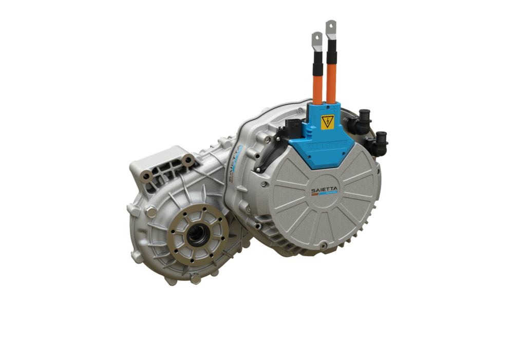
Axial flux motors
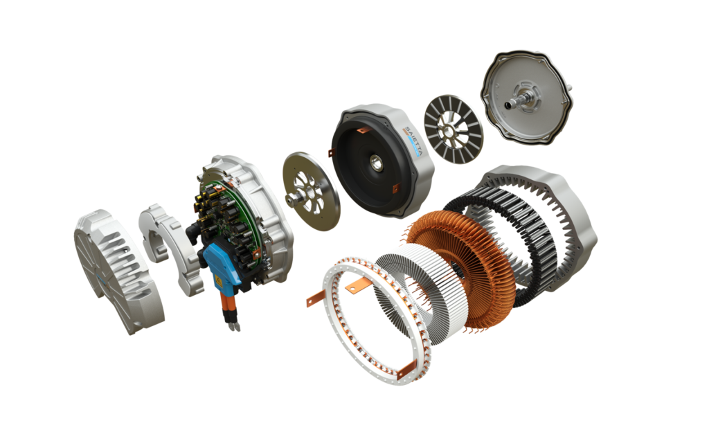
(Courtesy of Saietta)
The flat pack
Peter Donaldson canvasses expert opinions on the decisions to be made on whether to choose an axial flux motor for a given application
Axial flux (AF) motors are attracting a great deal of attention and engineering effort in the e-mobility arena, and for good reasons. Different motor topologies – such as radial and axial flux – are best suited to different applications, and each comes with its own set of pros, cons and development challenges.
The main distinguishing feature of an AF motor is that the magnetic flux that is central to generating torque moves in a path that is parallel to the motor’s axis of rotation. With radial flux (RF) motors, the flux follows a path that is radial or perpendicular to the axis of rotation. The rotor of an AF motor, therefore, spins beside the stator (or above or below it, depending on the motor’s orientation) rather than in the centre of or around the outside of the stator, as in RF motors.
We approached a number of leading motor and component developers and other experts to get a feel for the kind of decisions confronting engineers when choosing a motor architecture for their application. The available packaging space is one of the first factors to be considered. Pancake-shaped AF motors are a better fit where axial (lengthwise) space is at a premium, while more sausage-shaped RF motors are better suited to spaces in which there may be a diameter restriction.
A further consideration is whether the application needs a motor optimised for torque density or power density. Typically, AF motors are the better choice for the first, while RF motors are more suitable for the second because of their ability to run at higher rpm.
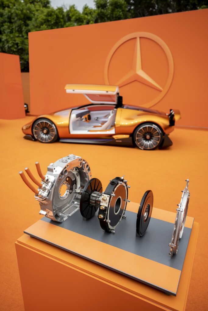
(Courtesy of Mercedes-Benz)
Need for speed
Speed also has to be thought about in terms of the relationship between the maximum speed and the base speed/torque knee point. That is the point on any motor’s performance curve at which the motor’s ability to produce torque begins to decrease as the rotational speed increases.
At speeds below the knee point, the motor can produce relatively high levels of torque, making it suitable for applications that require high starting torque, strong acceleration or the ability to handle heavy loads. Above the knee point, the torque begins to fall but it can operate more efficiently, making it suitable for applications that prioritise speed over torque.
AF motors are better at spinning slowly and generating high levels of torque, but permanent magnet AF motors in particular have high magnetic loading with low saliency, so they are limited in their field-weakening capability compared to RF interior permanent magnet motors.
As an aside, saliency refers to the amount of change in reluctance with rotor position, reluctance being the magnetic analogue of electrical resistance. A motor with low saliency will exhibit little change in reluctance with rotor position. For some applications, saliency is engineered into motors to improve control, efficiency and torque.
It could also be important to consider whether peak power or continuous power is more important for an application, as this can have an impact on the choice of motor architecture. In this respect, AF motors support high peak power density but often face limitations in continuous power density because of thermal challenges. This is particularly true of yokeless AF motors with a central stator that has a limited, primarily radial heat rejection path.
The topology of an AF motor, in which the large diameter of the rotor puts a large proportion of the magnetic material near the perimeter of the rotor, allows an increase in torque. It is generally accepted that the AF topology produces 30-40% more torque than a similarly powerful radial machine.
However, an AF motor with a yokeless and segmented armature configuration will typically double that torque advantage. “When combined with the reduced weight, this means figures approaching four times the gravimetric torque density of current mainstream RF machines can be achieved,” one expert says.
“Usually when speccing an AF motor, you would end up with something that has a much shorter axial length but is larger in diameter,” he adds. “Thanks to some thermal and magnetic tricks, yokeless and segmented armature machines have a similar radius to an RF example of equivalent powerful but maintain that much higher torque. As AF motors typically also run at lower speeds, this can influence the requirements of the transmission type and, again, on packaging.”
Systems thinking
Electric and hybrid aerospace applications present their own set of considerations regarding the choice between AF and RF motor topologies, which overlap with those affecting other applications but in an intensified manner.
“Due to the number of parameters and variables involved, not only in the motor but in the whole propulsion system, the engineer is faced with a non-trivial challenge when assessing the optimal motor to deliver the whole system’s requirements,” an aviation motor expert says. “Oversights in assessing which motor to select for their given application can have significant downstream effects – affecting cost, time to market, even airframe design and whether the mission profile is achievable.”
This developer also focuses on yokeless and segmented armature AF machines, and stresses that removing the motor’s yoke saves between 60 and 80% of the iron mass in the stator over a comparable RF machine.
The large number of variables means that a whole-system approach is essential to making the optimum choice for the application. The aviation motor developer takes all the system’s parameters and uses its genetic algorithm toolkit to program the aircraft’s duty cycles into its simulation system; the parameters include propeller speeds, flight durations and other elements related to performance.

“Then we run hundreds of simulations using our algorithm to help the engineer identify the optimum motor solution in a whole-system context,” their expert says. “What used to take our customers a year to develop and learn can now be done within a few weeks.”
In the design of any high-performance motor, optimising key components to reduce losses and increase efficiency, torque density and power density is a crucial part of the process.
An electric, hydraulic and mechanical powertrain provider notes that AF and RF motors have a lot in common in these areas. “If high efficiency is the target, an AF architecture enables smart design solutions, especially for the stator, to reduce the losses,” their expert says. “These solutions also support high power density, as the power of electric motors is usually assigned to a certain time like 30 seconds peak power and at least 30 minutes continuous power.”
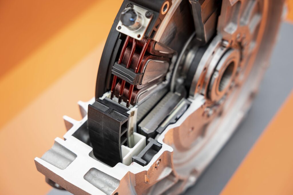
(Courtesy of Mercedes-Benz)
Minimising losses
All motor engineers strive to maximise efficiency by minimising energy losses. Among the most important things to look at are direct cooling of the rotor, addressing eddy current losses in stator cores and rotor back-iron. An academic in the area points to yokeless stator design, which reduces both weight and iron losses. It is also important to consider the size of stator winding heads.
“This can come in the form of winding layout and length, minimising harmonic losses, working to optimise the relationship between motor and inverter, or direct oil cooling,” says an expert from an AF motor developer that pioneered direct oil cooling and to which its single-rotor, dual-stator technology is well-suited.
“There is a move to use higher performance materials to aid with rotor speed and therefore power density, and our AF motors have very short windings and short, direct flux paths, further helping to minimise losses.”
Among the most important issues to address when seeking to minimise losses is AC copper loss. This results from I2R power loss, skin and proximity effects – particularly for concentrated windings with relatively wide ribbon conductors and open slots – according to the first motor developer.
In the skin effect, magnetic fields generated by high-frequency AC induce eddy currents that flow near the outer edges of the conductor so that current is unevenly distributed through the cross-section, increasing resistance. The proximity effect also alters the distribution of the current within conductors in a way that increases resistance. In this case, when multiple conductors carrying AC are in close proximity, their electromagnetic fields interact so that in each conductor the current density is higher on the side facing away from its neighbours.
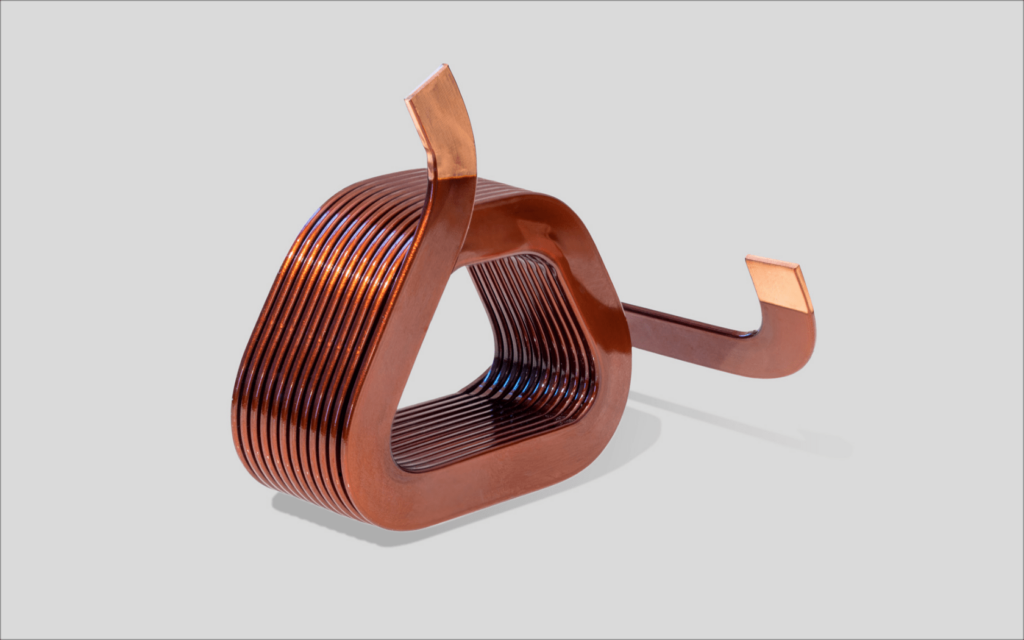
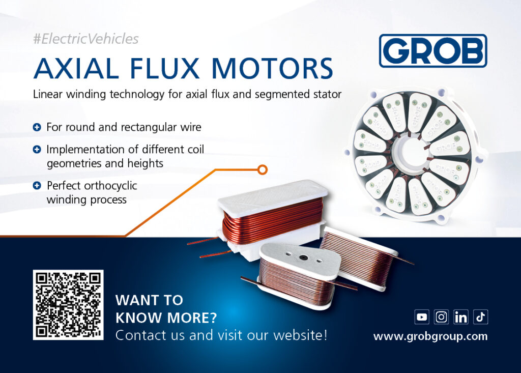
Techniques to mitigate the skin effect include the use of litz wire, which consists of individually insulated strands that are twisted or woven into cables and provide multiple paths for the current. Conductor shaping can also help, with flat or hollow wires that are less susceptible to skin and proximity effects than round conductors.
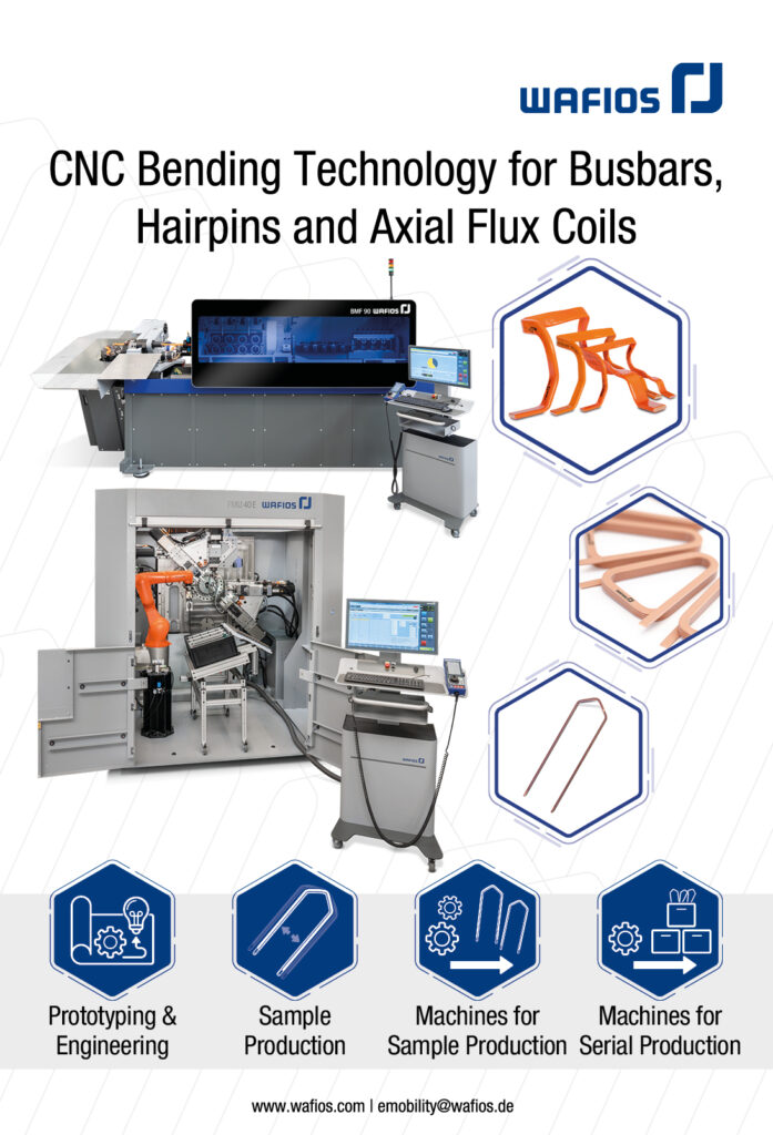
The use of flat wire also contributes to higher power density, a wire bending specialist notes. He adds that the technology used to bend the wires is important to avoid imperfections such as thickening at the corners, and that optimising the wire cross-section helps reduce losses from the causes above mentioned, with a focus on greater width-to-height ratios.
Eddy current loss in the permanent magnets can also arise in electrical machines, including AF motors, from various causes. These include space harmonics, particularly sub-harmonics from concentrated windings, time harmonics from the inverter switching, and high ripple currents caused by low winding inductance, the first motor developer explains.
Inverter-driven motors are provided with AC voltage as short pulses rather than a continuous sinusoidal waveform, which introduces harmonic components. These can cause current and magnetic flux distortion that in turn can affect the operation of the motor and bring additional losses.
One developer notes that the company’s own AF motors don’t require magnet segmentation or rotor back-iron lamination, because the flux density distribution from its distributed winding is highly sinusoidal.
Thermal design is also important to ensure adequate heat rejection from the windings and magnets.
In aerospace applications, minimising losses is crucial to the power density, low mass and high efficiency that aircraft demand. “If you were to look at the small changes we have made during the design of our AF motor, it could be elements like the pole bar in the copper we use, and whether there is a noticeable impact from changing it by half a millimetre in height or changing the thickness of the copper,” the aircraft motor specialist comments.
He reiterates the importance of looking at the system as a whole, rather than the motor alone. “For example, one way to improve your efficiency is to increase the amount of copper, as copper doesn’t get as hot,” he explains. “But there’s a point of diminishing returns, after which you are just adding weight and volume.
“So in optimisation, there’s a lot of analysis to find that point. Also, if you drive the motor in a non-optimised way it will be very lossy, so we also consider how to drive the motor with the controller and the software.”
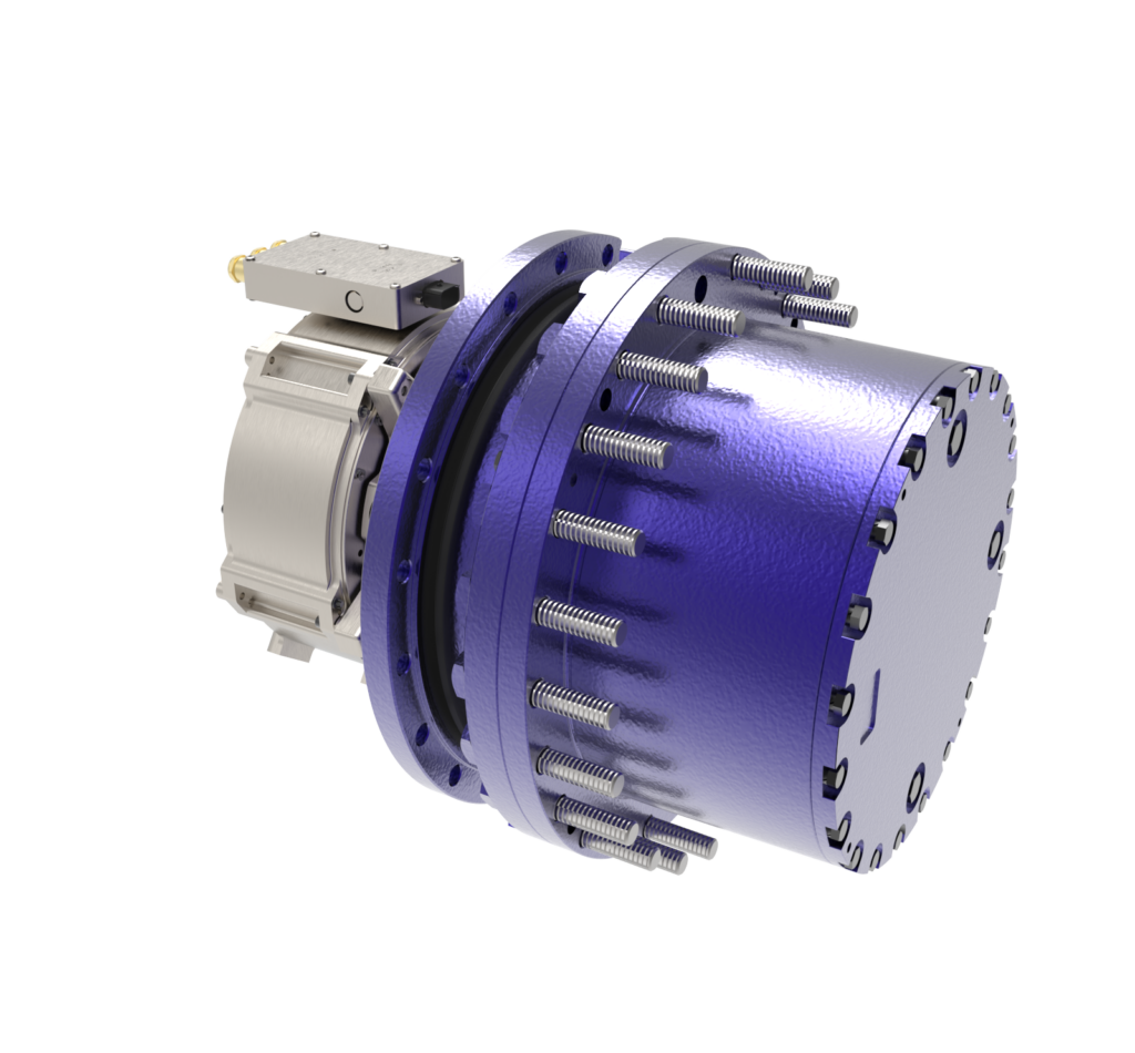
(Courtesy of Omni Powertrain Technologies)
Structural considerations
The architecture of AF motors places a number of mechanical demands on the magnets. One particular demand is on securing magnets to the rotor back-iron plate to withstand the high radial forces generated by high rotational speeds.
The composition of the magnets is not dissimilar to that used in RF, but their form and the way in which they are used are clearly different, and a lot of development attention is paid to cope with the tip forces generated by high rotational speeds of a larger rotor spinning alongside a stator, another expert notes.
Ferromagnetic material cannot be used circumferentially between the magnets to prevent rotational acceleration from shearing them out of register on the rotor or rotors, because that would short-circuit the magnets and reduce their useful magnetic flux, another AF motor developer explains.
Their expert says the magnets need to be robustly adhered to a back-iron in the case of yokeless dual-rotor, single-stator AF motors, where the back-iron is needed to close the flux path. Alternatively, in dual-stator, single-rotor AF motors, where the flux passes straight through the rotor, the magnets tend to be housed in complicated composite cage structures.
“For most other AF motors – particularly yokeless designs with concentrated windings – the flux harmonics experienced by the magnets leads to very high eddy current losses within them unless they are highly segmented, which means cutting them into small pieces that are then bonded together with an electrically insulating layer.”

“What we are aiming for is to push our magnetic machine hard, which then gets the magnets very hot,” the aviation motor developer says. “We then dump and dissipate the heat from those magnets effectively so that they do not become demagnetised, which would cause permanent damage to the motor.”
Staying cool
The flat, thin basic shape of an AF motor provides a high surface area-to-volume ratio that is beneficial for cooling, but other aspects of the general architecture and different AF motor topologies complicate the picture.
The AF topology maximises heat transfer from the magnets and into the surrounding structure, aided by other innovations around direct cooling to dissipate heat quickly.
“This is the key aim of any magnetic machine, and axial flux motors can do it better than radial motors as the magnets are not cocooned inside other materials, so they can dissipate the heat quickly and efficiently,” one expert says. “In a radial flux motor the heat is dissipated by conduction through multiple layers before reaching an outer cooling jacket, which is simply not as efficient.
“The AF machine also has other thermal management advantages. The heat generated in the coils can be removed efficiently by pumping oil directly over the coils and then transferring the oil to a radiator outside the motor.”
Implementing liquid cooling for stators faces challenges in ensuring good flow around the stator cores and to ensure leak tightness, the academic expert notes.
Despite some inherent advantages of the general architecture, innovative approaches to thermal management of AF motors have to be taken. For example, the yokeless and segmented armature topology allows fully sealed oil cooling of the stator elements, a solution that is not currently possible with RF motors, the second AF motor developer points out.
Further, yokeless segmented armature designs featuring dual rotors place the outer face of each rotor in the open air, where it is easy to reject heat, whereas an AF topology with dual stators and a single rotor has that rotor permanently sandwiched in a hot environment, he says.
Counter-intuitively, however, AF motors that place stators either side of the rotor, which is known as the inner runner (or inrunner) topology, have advantages in terms of losses when oil spray cooling is used, the electric, hydraulic and mechanical powertrain provider says.
“In our AF motor there is only one thermal interface between the coils and the outside of the motor,” the aerospace motor developer notes. “The ability of our topology to efficiently cool the magnets in the rotor and the coils in the stator is one of the main reasons why we can achieve higher continuous power than a radial motor.”
He adds that a really well designed radial motor for propulsion might deliver only 65-75% of peak power continuously owing to thermal limitations, while one of his company’s yokeless AF motors has a much higher continuous power rating at above 90%, thanks to improved high thermal-contact cooling. Oil cooling also offers extra insulation between electrical components offering another layer of protection.
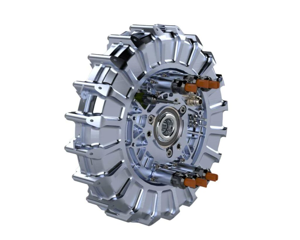
(Courtesy of Saietta)
Integration issues
The differences in shape and torque characteristics that AF motors exhibit bring opportunities as well as challenges for integration into vehicle drivetrains. Benefits include more freedom in design for a range of applications such as e-axles and wheel hub drives, while leaving more space for batteries and passengers, but managing the production of numerous variants can be challenging, our academic cautions.
Because the required wheel torque is delivered at lower motor speed, fewer reduction stages are needed. That places less of a burden on transmission components in terms of lubrication, potentially leading to longer service lives.
However, a parallel shaft, single-speed transmission might impose a diameter restriction on an AF motor in order to allow the vehicle’s driveshaft to clear the motor housing. One expert notes that AF motors are often more suitable than RF motors for near-wheel or in-wheel solutions in applications such as skateboard platforms for last-mile delivery vehicles designed to maximise the width of the load bed, for example.

The shorter axial length of a yokeless and segmented armature AF machine, combined with an outer diameter similar to typical RF machines, provides real benefits in packaging, the second AF motor developer claim. Ferrari’s hybrids using such motors provide an example here.
“An RF motor would simply not fit in the back of a V8 without increasing the length of the entire vehicle,” one AF motor developer’s expert points out. “The much wider low-speed continuous torque band of an AF motor changes the requirement for gearboxes. Where an RF motor typically runs at higher rpm, there is not sufficient torque at lower rpm, which could mean having to use a two-speed gearbox.”
The pancake shape makes the AF motor a good fit for aircraft. “If it has a gearbox, usually it is a comparable diameter, which allows you to stack one or more motors very easily without causing too big of an impact on the aircraft design,” the aviation specialist says.
“That gives you great benefits, and if we are talking about eVTOL applications where motors are mounted, it’s even more critical where you have to fit the motor between firewalls or structural members, so shorter is better.”
He also argues that the speed limitations of AF motors are not as restrictive as might be assumed. “We are currently using our axial flux machines far beneath their capable mechanical speed – we have lots of potential left to find.”
The powertrain developer argues that AF and RF machines can be engineered to provide very similar torque characteristics, emphasising that the company can provide motors with almost any reasonable torque and speed characteristics, and there is an analogous flexibility in terms of packaging, its expert says.
“While the shapes of AF and RF motors are different, with an integrated motor, inverter, and transmission systems you can end up with about the same package, but with higher performance per unit volume and weight for AF motor solutions.”
Observing the evolution of applications at one remove from the motor developers themselves, the wire bending specialist notes that AF motors allow a lot of design freedom for wheel hub drives, e-axles and even in-wheel applications. However, the need for a motor at each wheel adds more components such as inverters to the system and thereby increases costs.
(Image courtesy of Evolito)
Control questions
Controlling AF motors efficiently, particularly under dynamic driving conditions, naturally means taking their inherent electromagnetic characteristics into account. One developer explains that AF motors typically don’t exhibit any significant saliency.
“That means all the torque is produced from the interaction with the permanent magnet flux, there being no reluctance torque component,” its expert explains. “However, this simplifies the control of the machine, as torque is simply proportional to the q-axis current, and negative d-axis current is used for field weakening as required. Maps are therefore not required for effective maximum torque-per-ampere control.”
He notes that one challenge stems from the fact that AF motors usually have relatively low winding inductance. “This means that either a high switching frequency or a multi-level inverter topology is necessary to keep the current ripple low. Otherwise, high current ripple leads to additional loss in the machine and increased noise, vibration and harshness [NVH].
“On a positive note, the lower inductance means the torque control of the machine is very responsive, exhibiting high-bandwidth control of the current.”
NVH finesse
NVH is a major topic in vehicle design as a whole, and must also be considered in AF motor design and development.
Key aspects of design include nominal air gap size and expected variations in it resulting from factors such as rotors not being perfectly parallel, differences between air gaps, tolerance stacks and so on. Also important are rotor vibration modes and their natural frequencies, which are affected by stiffness and mass, and rotor balance.
From the electromagnetic point of view, an expert says, NVH performance is impacted by the amplitude and frequency of cogging torque, which is affected by factors such as slot opening, skewing, slot/pole combination, and concentrated versus distributed winding configurations.
Mechanically, large rotor diameters and high rotation speeds bring a risk of vibration. The academic expert suggests that an additional air gap bearing on the outer diameter of the rotor could provide a solution, but acknowledges that it would entail some loss of efficiency.
One AF motor developer points to the application of current harmonic injection, explaining that it is particularly good for addressing NVH issues in AF motors and, in its simplest form, operates in a similar way to noise-cancelling headphones.
“NVH is always a system-related issue,” another expert points out. “Motor, inverter and transmission have to be tuned together to achieve the best NVH properties.”
Reliability and longevity
As with any relatively new technology, a vital aspect of the engineering effort that goes into RF motors is ensuring their reliability and durability, particularly in harsh environments and over high mileages and thousands of operating hours. Careful design of the sealing for liquid-cooling channels and of the internal motor cavity to protect it from the external environment is vital, for example.
Other key considerations include bearing loads, bearing alignment and axial preloads. Extensive durability testing that exposes motors to both thermal shock and vibration is also crucial.
The importance of such testing is magnified in aerospace because of the safety-critical nature of the powerplant. The aircraft AF motor expert emphasises the importance of specific durability testing and highly accelerated life testing.
“Throughout this, we subject the motor to repeated cycles that escalate in severity of vibration, temperature and performance.”
A deep understanding of how the machines are designed and how they fail is also crucial. “This starts with a fault tree analysis, where we look at every component and analyse how they could fail and then remove or protect against those causes through design.”
While regulatory standards and safety requirements don’t take motor architecture into account, AF architecture and related design details do present some safety benefits, a couple of our developers say. All the high-voltage elements of the motor are buried deep within the machine and isolated in a dielectric oil, reducing the risk of short-circuits to the chassis.
The aerospace motor developer points to the separation between coils in it AF machines, saying, “They are separated not only through physical clearance but also through immersion in a dielectric oil. No coil has any overlapping connection touching another coil, which is really difficult to do on a radial machine.” This makes them much more robust to electrical failures.
Future directions
AF motor developers continue to improve their core products in terms of power density, efficiency and integration into drivelines. One developer highlights improved stator encapsulation and better manufacturing techniques, plus the integration of a motor control unit that shares the housing and coolant with its motor, eliminating phase cables. The company has also developed a bespoke single-speed transmission with multiple gear ratio options that provides a ‘cost-optimised’ e-drive.
Another developer points to a multiplication in power density, from a few kW/kg a decade ago to around 15 kW/kg in its production motors. It plans to double this as well.
The aviation specialist reports power density increasing by a third over the past 18 months. Meanwhile, it has also been working on what its expert refers to as dual electric architectures that enable them to fit two AF motors side by side in the same size package as a single motor. “This has major benefits for the safety profile of any fully electric aircraft,” he says.
The electric, hydraulic and mechanical powertrain specialist points to breakthroughs in manufacturing processes and motor design that have enabled higher cycle rates in production. It has also designed an oil-cooled AF motor with a very high continuous power that is intended for commercial vehicles.
Future improvements in the core technology are likely to focus on higher rotational speeds leading to higher power density, this being enabled by lighter rotors that are better balanced and assembled with finer control of air gap tolerances.
Another r&d goal is further reduction of eddy current losses in magnets through lower space harmonics (variations in the distribution of magnetic field strength) in the windings’ magneto motive force, along with shielding against high-frequency flux harmonics. A third direction is increased inverter switching frequency, multi-level inverters and/or more advanced modulation schemes to reduce current harmonics and improve voltage utilisation.
Finally, increased rotor saliency and flux focusing could take some pressure off the supply of rare earth magnets by easing requirements on the grade and volume of magnetic material needed.
Acknowledgements
The author would like to thank Dr Chris Lines at Saietta, Dr Tim Woolmer and Simon Odling at YASA, Mukesh Patel, at Evolito, Martin Bauer at Wafios, Dave Kemper at Omni Powertrain Technologies, and Henrik Born at RWTH Aachen University for their help with researching this article.
Click here to read the latest issue of E-Mobility Engineering.
Some suppliers of axial flux motors
Australia
brandgroup
thyssenkrupp Steel
Wafios
Italy
+49 2947 889 0
+49 203 52 0
+49 7121 146 0
Lucci R
GROB Italy
Slovenia
+39 0541 739211
+39 011 934 8292
Evolito
Horizon Technologies
Saietta Electric Drive
Oxford Propulsion
YASA
+44 1865 967700
+44 2036 089996
+44 1869 233121
+44 1865 802480
+44 1865 952 100
USA
Arnold Magnetics
Omni Powertrain Technologies
Turntide Technologies
+1 585 385 9010
+1 713 635 6331
+1 877 776 8470
ONLINE PARTNERS
