


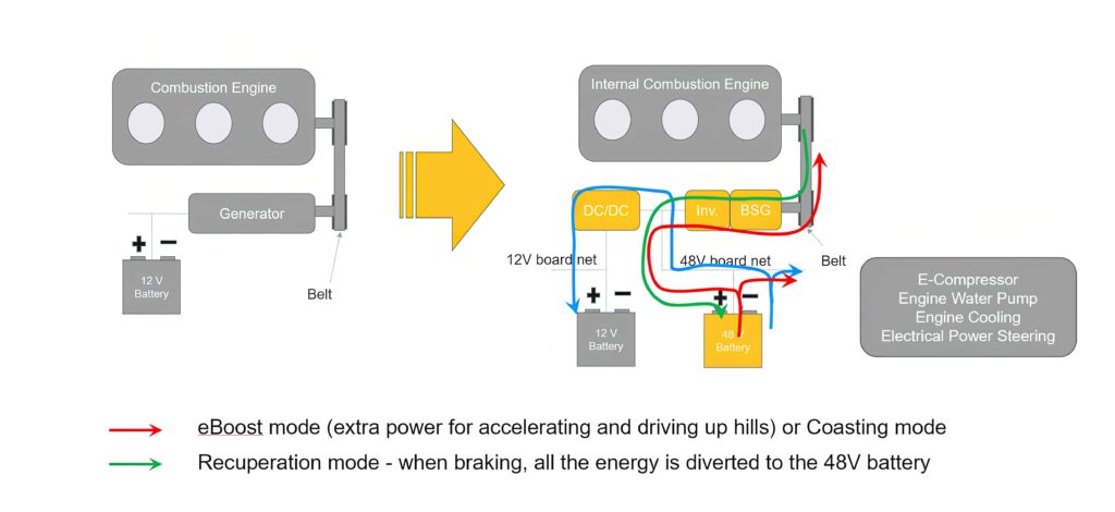
48 V systems
(Courtesy of Continental)
Potential difference
Moving to power distribution networks running on 48 V looks set to confer a range of benefits to battery-electric vehicles. Nick Flaherty reports
Technology based on 48 V has been adopted for electric motors and battery packs to reduce emissions in mild hybrid vehicles, but changing regulations are seeing even those being banned from as early as 2030. This leaves mild hybrids with a limited window for development, which is driving a more modular approach to the development of the powertrain technology for use in wider applications, from two- and three-wheelers to off-road construction equipment.
At the same time, the high volume of hybrid production has driven down the cost of 48 V motors and battery packs, opening up the other applications. Moving some parts of the powertrain to 48 V is also highlighting the advantages in other parts of the vehicle of direct 48 V operation, such as heating and air conditioning.
This in turn has driven the development of local DC-DC converters and passive components such as capacitors and inductors suitable for 48 V designs that could see the technology being adopted in full battery-electric designs, converting the 400 or 800 V output of the battery pack to 48 V for distribution around the vehicle.
The advantage of a 48 V power distribution network to replace legacy 12 V systems is more significant when much higher currents are flowing. Supported by DC-DC converters that can provide the 48 V supply, the move to 48 V can cut the size and weight of the cable harness dramatically, as a 48 V cable is half the diameter of a 12 V one. This supports existing 48 V DC-DC converter designs that will drive 12 V subsystems, and also opens up point-of-load (PoL) designs for supplying increasingly power-hungry ECUs handling ADAS safety systems and even the central controllers for autonomous driving in full battery electric vehicles.
Mild hybrid designs
Mild hybrids make conventional IC engines much more efficient thanks to a relatively simple upgrade that can include recovering kinetic energy from braking.
This energy is stored in a relatively small 48 V battery, typically up to 1 kWh, and used to support a 48 V motor that handles start-stop operation. This cuts fuel consumption by 15% or more, and thus reduces CO2 emissions accordingly.
In the simplest arrangement, called P0, the conventional 12 V generator is replaced directly by a 48 V machine, often called a boost recuperation machine, and an inverter. This converts kinetic energy into electrical energy during braking and stores it in the 48 V battery. It also supports the IC engine with up to 12 kW of power. In addition, safety-relevant functions such as driver assistance functions or electric brake boosters can be reliably supplied with 48 V voltage.
There are other topologies for the 48 V motor in other parts of the powertrain. The P1 configuration see the motor installed between the IC engine and the transmission, but this is rarely used in practice.
The P2 approach indicates an integration directly on the side of the main transmission or connected via a belt, while P3 has the motor sitting directly behind it on the driveshaft. Both topologies are mechanically much more complex than P0. For example, the e-motor needs to be installed in the transmission as individual components, not as a whole, and air cooling is not possible. In addition, a starter motor is usually still needed in this set-up, which increases costs.
Integrating one or two 48 V motors on the rear axle via a differential gear provides the full-hybrid, P4 option. This has the lowest frictional losses in the powertrain, with emission savings of up to 25%.
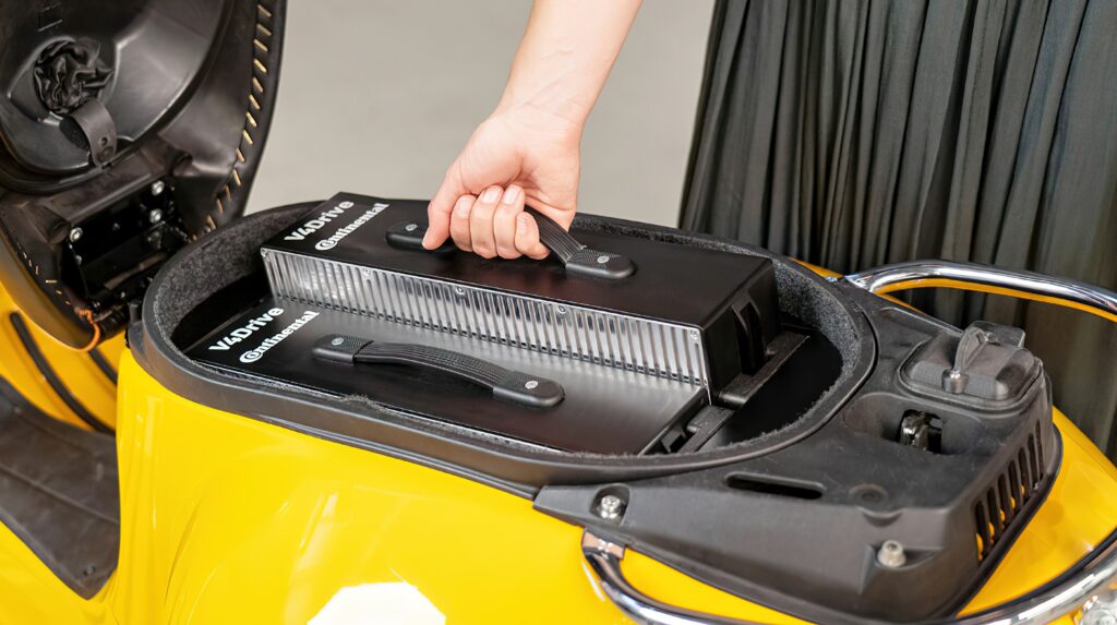
The use of 48 V motors, battery packs and inverters is also opening up applications such as e-scooters to electric rickshaws and minivans. For example, a 9 kg lithium-ion 48 V battery pack gives a range of 50 km and power of 10 kW. It can be detached simply and charged externally. Multiple packs can be connected and controlled via a dedicated battery management system, doubling the range to 100 km by using two batteries.
48 V is also opening up the use of gallium nitride (GaN) switches. For example, for smaller 1 kW motors for e-scooters, a three-phase 48 V brushless DC motor drive inverter uses an 80 V GaN transistor running at 100 kHz.
The higher efficiency of running at this frequency, and the lower on-resistance of 2.2 mΩ of the GaN switch, supports 15 A of steady-state current with a 50 C temperature rise in natural air convection, and can reach 20 A rms (28 A peak) with a heat sink attached. The design has been tested with a 60 V input and 50 A peak current.
(Courtesy of Yageo)
Switching in the 100 kHz range also eliminates the need for electrolytic capacitors and reduces the motor losses. Reducing the ‘dead’ time of the GaN switch to about 20 ns provides higher torque per amp, as well as providing lower distortion for a quieter design, lower current ripple for reduced magnetic loss, lower torque ripple for improved precision and less need for filtering for lower cost.
All this allows a complete motor drive inverter in only 130 x 100 mm including the connector, enabling the inverter to be integrated inside the motor.
Commercial vehicles
In the commercial vehicle sector, 48 V motors can provide the start-stop function for light trucks as well as supporting the mild hybridisation of heavy trucks.
There are three main drivers for commercial vehicles, starting with reducing diesel and nitrous oxide emissions to meet increasingly tight regulations. This is achieved by using the 48 V supply for a heater for the IC engine’s catalyst to provide more efficient operation, especially at low load.
For just generating power for an electric heater, the P0 topology is the simplest and has the lowest cost, as it doesn’t need energy storage with a DC-DC converter to the 12 V base electrical system. There are 48 V alternators being developed that could provide 12-13 kW – 10 kW for the heating and 2-3 kW for base load.
The second driver is to reduce CO2 emissions, by using the motor/generator to capture energy when slowing down and to accelerate the vehicle, and to power accessories such as an engine cooling fan, air conditioning and exhaust gas recirculation pumps. These require 48 V energy storage, which depends on duty cycle but typically entails a battery capacity of 5-10 kWh, although 35 kW is the upper limit for 48 V systems.
(Courtesy of Dana)
In some cases the key metrics are the charging rate, or C rate, and the energy absorbed, so a supercapacitor can be used. This is particularly useful in vehicle designs such as buses that have numerous stop-start cycles.
For battery-electric systems, that means there are three electric buses, handling the high voltage from the battery pack at 400 or 800V, the 48 V bus and the 12 V bus. This then requires 48 V to 12 V DC-DC buck-boot converters with support for the high currents for heaters and air conditioning, each typically around 5 kW. The DC-DC converters use silicon MOSFETs and have an efficiency of around 97%.
Feeding 10 kW of power to a coil has to be handled without disrupting the base electrical system, and to regulate that power requires a specialised, air-cooled power controller that can be placed in different areas of a commercial vehicle design. This would typically be placed close to the battery pack to operate at the 65 C ambient temperature without the need for a fan.
Motor designs
For mild hybrids, the electric machine tends to be an induction motor rather than a permanent magnet (PM) type, as the torque requirement is less, although car makers are looking at alternatives to induction motors to increase the power and torque density to achieve the target power density of 100 kW/litre determined by US requirements.
These include interior PM (IPM) motors and other switched reluctance motors (SRM) and there is academic research into these IPM and SRM technologies. These SRMs have traditionally not been used as they have noise and vibration issues and the torque is not as high as IPM as there is no magnet, but there are cost benefits as a result.
The key advantage of 48 V is that it is a low-voltage design, below 60 V. Above 60 V, all the requirements in the inverter change, so there are regulations that need to be considered for HV, such as isolation, clearance and creepage.
In an actual application the voltage in transient events may exceed 60 V but discharge circuitry is added to keep the voltage below that to avoid the creepage and clearance requirements that come with higher voltage designs.
The switching technology of silicon MOSFETs from 80 V to 100 V is also much cheaper than IGBT, silicon carbide (SiC) or GaN devices and easier to validate. MOSFETs are well-understood in switched-mode power supplies so there is a lot of expertise around, and they are very reliable
As the power goes up in the motors there is an increasing need to cool not only the stator lamination but the coils a well, in the form of oil cooling splashed onto the end windings of the stators. However, this means adding a pump and other structures so it makes the design more complicated. 48 V motors are currently rated to 50-60 kW but at 100 kW and beyond the design becomes more similar to battery EV motors and oil cooling becomes more critical.
48 V compressors
The move to 48 V and experience with electric motors in mild hybrids also provides a boost to other parts of a hybrid vehicle’s powertrain. The latest generation of 48 V compressor, or e-booster, for a turbocharger can improve the efficiency of an IC engine to reduce emissions, as it can be made smaller.
The e-booster’s design provides major improvements in efficiency and performance, maximising efficiency at low loads. Higher engine power output is achieved by separating electrical boosting from the turbocharger so that it can be matched to higher power, enabling lower back-pressure in the exhaust manifold and improving gas exchange.
This second generation of e-booster supports continuous power of 2.5 kW up to a maximum of 7 kW, compared with the first generation that enabled transient boosts up to 5 kW for 20 seconds per minute using a permanently excited synchronous motor (PMS). This reduced the energy requirement during acceleration substantially compared with a traditional reluctance motor. The PMS also significantly improved both noise, vibration and harshness and engine response, along with torque density and efficiency.
The second-generation e-booster continues to use the permanent magnet electrical motor but reduces the moment of inertia of the rigid rotor and compressor with a higher current of 160 A, up from 130 A and faster spool-up of 190 ms, up from 270 ms.
The design has a new EMC choke for lower power losses and enhanced filter effect, a stator linked to the power electronics for reduced resistance and improved efficiency, a microcontroller with added computing capacity for field-oriented control (FOC) and model-based software component protection for uninterrupted operation.
Another important upgrade in the second generation is the use of sinusoidal commutation in place of a block commutation. Sinusoidal commutation provides a smoother transition and generates fewer ripples in the current compared with more rapid variations with a block commutation. Sinusoidal commutation also enables lower eddy-current losses in the electrical motor to deliver higher peak power and continuous operation of the e-booster.
From the DC voltage, a three-phase commutation with variable frequency and amplitude is generated to drive the motor, and a sensorless FOC algorithm is used to generate signals for the switches of the three half-bridges of the power output stage.
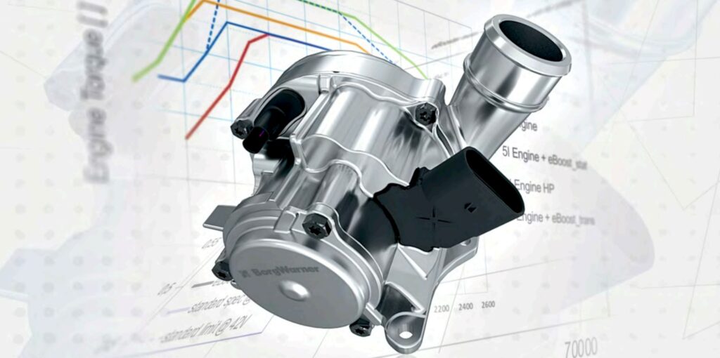
(Courtesy of BorgWarner)
For operation points at very low voltage or at high speed with reduced torque requirements, FOC enables the motor to operate in a field-weakening area by splitting the phase currents into two vectors, a field generating current (Id) and a torque generating current (Iq). This also supports faster current and speed control, current measurement of all three phases, 40 µs cycle time of the P1 controller, 28 kHz pulse width modulation (PWM), overcurrent protection for the hardware and software, and permanent boost from model-based component protection.
For 48 V systems under load and with a reasonable state of charge, the voltage is normally at 42 V. The limits at low voltage and higher speed can now be increased by 55% for a short time through the positive effect of the field weakening.
For enhanced component protection, the Gen2 e-booster’s PCB has three negative temperature coefficient sensors to measure coolant temperature in key areas along with the power electronic part of the PCB. A software model is used to measure these critical temperatures through the sensors. This allows intelligent derating of the e-booster to protect components based on the highest tolerable temperatures in critical areas.
This temperature model will protect components from excessive thermal loads even during heavy use. Calculated temperatures are transferred into a range of percentages that are used to develop a utilisation index, with the highest temperature setting the index percentage which is conveyed to the electronic control unit through a CAN interface. Temperature warnings and an overtemperature alert can then be raised according to the index.

The e-booster can also be used for commercial vehicles with engines up to 5 litres. The additional combustion air that can be added through this boosting technology now makes it possible for medium-duty engines to replace those that are 50-60% larger without losing power or torque, while maintaining and even improving transient behaviour.
Battery pack monitoring
Managing a 48 V lithium-ion battery pack is a critical task as there is less design margin compared with high voltage packs. These 48 V packs can have between four and 14 cells and require a monitoring accuracy of under 2 mV to accurately determine cell ageing. Using a dedicated data acquisition path for each cell allows the voltage of all the cells to be measured at the same time with the voltage and current synchronised by using 15 analogue-to-digital converters (ADCs), rather than using shared resources.
This monitoring is used for the functional safety requirements to determine over- and undervoltage, overheating or overcurrent. A cyclic redundancy check on the ADCs for cell monitoring ensures the accuracy, and if an ADC is not accurate enough, the monitor can move to a shared, round-robin scheme for a ‘limp home’ solution.
Intelligent power distribution
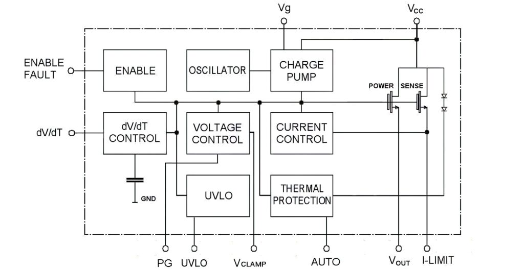
One of the major trends for 48 V power distribution is the replacement of relays and melting fuses with semiconductors for an intelligent power distribution system.
For safety-critical applications such as ADAS driver assistance, electronic fuses are 10 times faster, at 100 µs, than traditional fuses at 20-50 ms, as well as smaller, so the electronic version reduces the fuse box’s dimensions and weight. These electronic fuses are also fault-tolerant, and can be reset after being triggered rather than having to be replaced.
These electronic fuses are ‘load shaped’, where the cable size can be sized to the current and voltage characteristics rather than typical or standard wires. The latest devices can emulate the profile of a fuse to protect a PCB trace, a connector and/or wires from overheating without any impact on the load transients or current management. The fuses use a silicon MOSFET as the actuator and allows every power line to be intrinsically protected by the switch using a 5 x 5 leadless device that can still handle up to 300 A.
(Courtesy of STMicroelectronics)
DC-DC converter
Using 100 V GaN transistors for a high-density 48 V DC-DC power converter enables a system that is one-third smaller and 50% lighter than standard converters and has an overall efficiency of more than 95% compared with silicon-based designs.
The DC-DC converter has an input voltage range of 24-60 VDC and is rated at up to 1 kW of continuous power with an efficiency of 97.5% at full load – a 4% improvement on similar types of converters currently on the market. The power density is 28 W/cu in compared with 10 W/cu in in converters using other topologies and switches, and the design without the case weighs 345 g.
Testing
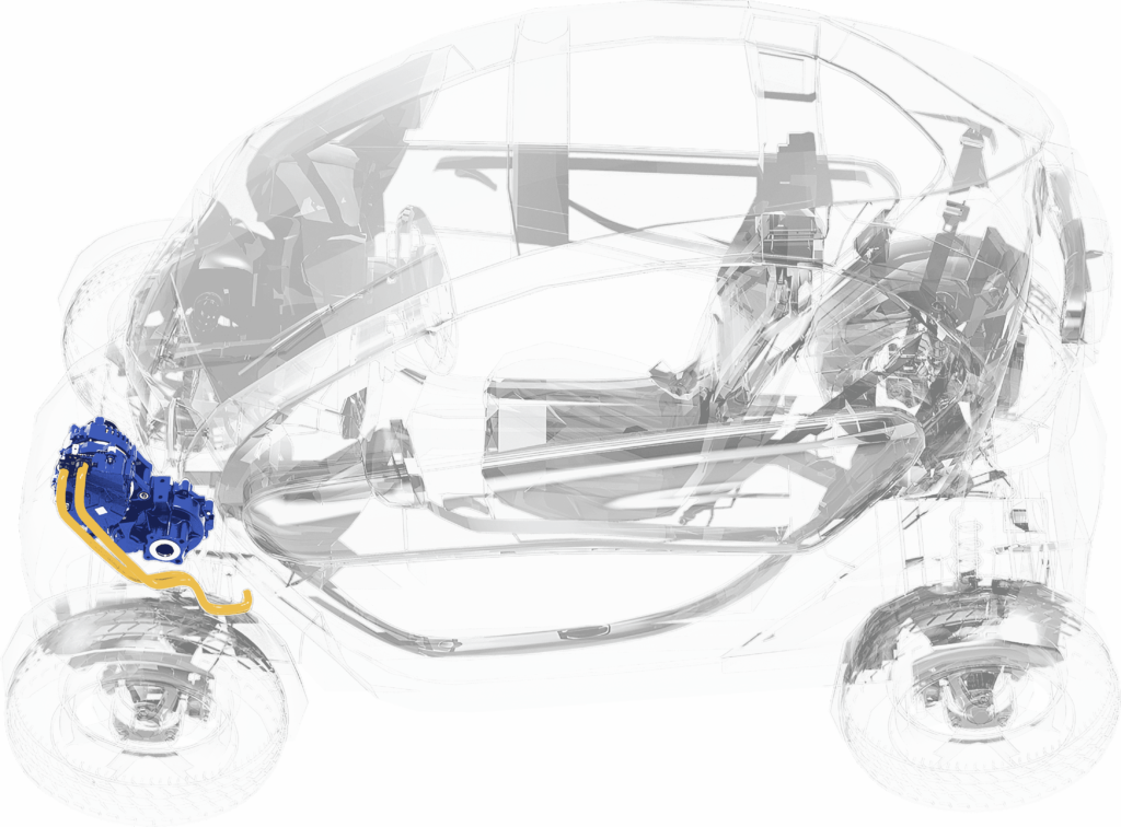
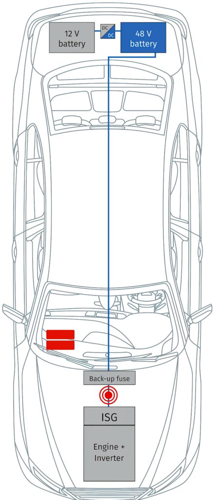
Testing the integrated starter/generator (ISG) is a key challenge. It is mounted between the flywheel of the engine and the transmission, and replaces the starter motor and alternator to provide hybrid functions such as boosting, energy recovery, load point shifting, coasting and start/stop, in P3 and P4 hybrids.
Current and voltage measurements at the input of the inverter are needed to obtain the optimum parameters for the starting operation.
Although the onboard supply voltage has been increased to 48 V, currents up to 300 A still occur. In situations such as engine start-up, there are even higher current peaks, which can seriously damage the 48 V battery. That means it is important to precisely measure the steady current and the peaks, which might last for only a few microseconds.
To perform measurements as close to the inverter as possible, a current sensor is mounted between the back-up fuse and the ISG. The measurement module and data collecting gateway are placed in the footwell of the passenger seat. The power electronics of the ISG also contains a current sensor that is checked via CAN bus. The comparison clearly shows that the internal sensor is operated at a far lower sampling rate. In addition, there is a distinctive signal delay owing to the lower bus performance.

A bandwidth of 100 kHz allows current peaks to be converted into high-resolution voltage signals. Contrary to conventional current sensors such as shunts, a Hall effect current sensor is inherently galvanically isolated from the measurement set-up, which means that there is no risk of a short-circuit.
Signal sampling with frequencies up to 1000 kHz makes it possible to display and analyse even very short current peaks in detail.
The gateway then converts signals into the standard XCP-on-Ethernet protocol, which allows the acquisition of measurement signals via standard data acquisition tools to integrate the system into a developer’s existing tool chain. As time stamps are assigned to the data, it is possible to establish time relations to other previously recorded measured quantities, for example CAN signals from various ECUs.
Other components
The inverter is the main focus for components supporting 48 V designs, but there is also demand for 48 V in compressors and heaters, water pumps and other subsystems using 48 V. This puts more pressure on the design of passive components such as capacitors where the main engineering challenges are the filter for EMI and the DC-link capacitor.
One approach is to use a hybrid capacitor that uses a wet electrolyte and a polymer electrolyte to get the reliability needed for automotive designs at 48 V with smaller size and higher current capability than 12 V devices. The design of the capacitor depends on the combination of the electrolyte and the polymer. If the area is not well-distributed, localised self-heating occurs and the electrolyte will deteriorate, shortening the lifetime of the device
(Courtesy of CSM)
For the DC-link capacitors in an 11 kW 48 V inverter, for example, using a hybrid capacitor can reduce the space required by 40% by replacing five electrolytic capacitors with three hybrid devices measuring 18 x 35 mm. Alternatively, five hybrid devices in the same space can handle 45% more current, allowing a power of 16 kW. This higher power is being requested for P4 hybrid designs.
The EMI filter has a different set of requirements with the higher currents at 48 V, meaning traditional differential choke filters cannot be used.
Here, a ferrite core material sits directly on the busbar in differential or bus mode. The dual-mode choke with a magnetic node between the busbars increases the differential mode between the bus bars to 250-300 A.
The EMC filter between the main PCB and the DC supply can use a choke that can work as a filter in both common and differential modes in a single part. The ferrite outer ring of the choke is used as the common mode path, and the tongue is combined with an air gap and the outer ring as a defined differential mode path. This provides for low DC losses owing to the busbar’s low current density, while the differential mode can be influenced by the core design with the flux remaining mostly in the ferrite core.
Ferrite materials with an attenuation of 5000 mu can operate up to 150 C and 1 MHz to prevent any EMI noise in the AM band.
For 48 to 12 V DC-DC converters, tantalum and polymer capacitors are used to filter the output of the converter, the main difference being the lifetime and mechanical aspects of the equivalent series inductance and resistance (ESL and ESR).
One important point is to take a modular approach to design. Designers are using pre-assembled capacitor arrays in parallel with the busbars to go directly on the AC side so they don’t need to worry about soldering issues, which can cause failures. This allows a low ESL based on the busbar topology by compensating for the inductance of the positive and negative busbar by putting them close together.
48 V power distribution
Adding a 48 V battery to power a heavier powertrain and chassis-system loads provides options to engineers. Now there is a choice of adding systems that can deal directly with a 48 V input, or to retain legacy 12 V electromechanical loads such as pumps, fans and motors and instead convert the 48 V to 12 V via a regulated DC-DC converter.
Mild-hybrid power delivery systems are slowly adding 48 V loads but still use a large centralised multi-kW 48-12 V converter that feeds 12 V around the vehicle to the 12 V loads. However, this centralised architecture does not take the full advantage of a 48 V power distribution network and cannot take advantage of improvements in DC-DC converter topologies, control systems and packaging.
The vast majority of these centralised DC-DC converters are bulky and heavy, since they use older low-frequency switching PWM topologies. They also represent a single point of failure for many critical powertrain systems.
Using a decentralised power delivery with modular power components enables smaller, lower-power 48-12 V converters, distributed throughout the vehicle close to the 12 V loads for higher efficiency and lower losses. For a given power level, the current is four times lower at 48 V than in a 12 V system and has 16 times lower losses.
At a quarter of the current, the cables and connectors can be smaller, lighter and cheaper. The decentralised power architecture also has significant thermal management and power system redundancy benefits.
The 48 V output from the battery is distributed to the various high-power loads in the vehicle, maximising the benefits of lower current and lower losses, and resulting in a physically smaller and lighter power network. Depending on a load power analysis of the various distributed loads, one module can be designed and qualified for the right power granularity and scale to be used in parallel arrays.
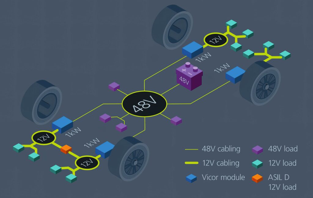
(Courtesy of Vicor)
By using distributed modules instead of a large centralised DC-DC converter, N+1 redundancy is also possible at a much lower cost. This approach also has advantages if the load power changes during the vehicle’s development phase. Instead of implementing changes to a full ground-up custom power supply, engineers can either add or eliminate modules. Another design advantage is reduced development time, as the module is already approved and qualified
A 48 V power distribution network still has significant benefits, but now the power system designer has the additional challenge of a high-power 800-48 V or 400-48 V conversion, which requires isolation but not regulation. Better voltage regulation is one benefit of decentralising the placement of 48-12 V converters.
By using regulated PoL converters, the high-power upstream converter can use a fixed-ratio topology. This is extremely beneficial owing to the wide input-to-output voltage range of 16:1 or 8:1 for 800-48 V and 400-48 V respectively, but using a regulated converter over this range is very inefficient and presents a large thermal management problem. It would be very difficult and costly to decentralise this high-voltage isolated converter owing to safety requirements in distributing the 400 or 800 V.
However, a high-power centralised fixed-ratio converter can be designed using power modules instead of a large DC-DC converter. Power modules of a suitable power level can be developed and then easily paralleled for a range of vehicles with differing powertrain and chassis electrification requirements, with efficiencies of 98% and power densities of 2.6 kW/in3, significantly reducing the size of the centralised high-voltage converter.

Conclusion
Naturally there is an immediate focus on 48 V power distribution for mild hybrids, even though the P0 topology has a limited design life as hybrids are phased out from 2030 in many markets. The benefits of improvements in higher currents in 48 V subsystems, from compressors to pumps and heaters, is supporting higher power and efficiency across vehicle designs. This is also leading to the development of passive 48 V components, from capacitors to choke filters, that are optimised for higher power applications.
However, the emergence of 48 V mild-hybrid systems is also leading to the development of 48 V power distribution networks in battery-electric vehicles with much thinner and lighter wiring harnesses to cut vehicle weight. This is driving the development of unregulated 400/800-48 V DC-DC converters to power 48 V peripherals directly. This is also leading to local regulated PoL 48 V DC-DC converters to power electronics with a more efficient power distribution.
Acknowledgements
The author would like to thank Amir Ranjbar at Dana, Ben Karrer at Eaton, Martina Giuffrida at STMicroelectronics, Dr Jurgen Braunstein at CMS, and Alexander Nebel and Maawad Makdessi at Yageo for their help with researching this article.
Some suppliers of 48 V systems
France
Valeo +33 1 49 45 32 32 www.valeo.com
Germany
Avnet +49 8121 777 02 www.avnet.com
Elmos +49 231 75 49 0 www.elmos.com
FEV +49 241 5689 0 www.fev.com
Infineon +49 89 234 0 www.infineon.com
SEG Automotive +49 711 4009 8000 www.seg-automotive.com
Vitesco +49 941 2031 0 www.vitesco-technologies.com
The Netherlands
NXP +31 40 272 9999 www.nxp.com
Switzerland
STMicroelectronics +41 22 929 2929 www.st.com
Taiwan
Yageo +886 2 6629 9999 www.yageo.com
USA
Eaton +1 269 342 3000 www.eaton.com
Vicor +1 630 795 1417 www.vicor.com
ONLINE PARTNERS
