


Xerotech battery system
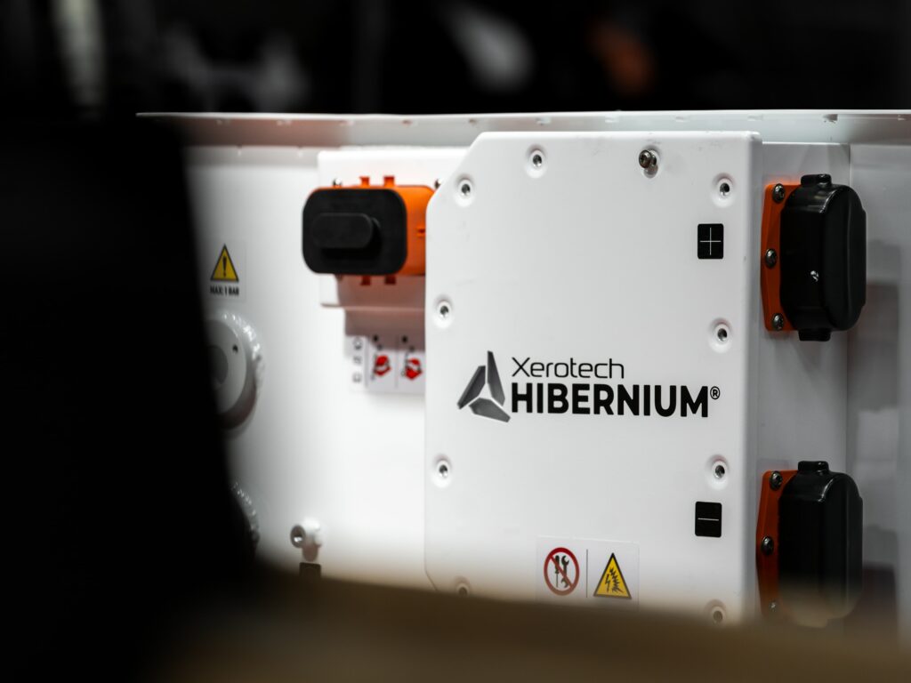
(Images courtesy of Xerotech)
Pick your pack
Unlike road EVs, off-highway vehicles need different battery solutions but in only small batches. Rory Jackson looks at how this company provides them
For on-highway vehicles, electrification is now seen as the way to go, but the future for electrified off-highway ones such as construction dozers, mining trucks and so on is less clear.
Off-highway mobile machines are often larger than the biggest on-road trucks, and vary widely in their size, power, cost, environmental harshness, and weight. For example, there are 0.5 t mini-excavators and 400 t haul trucks, and if you include non-terrestrial vehicles, there are 500 t aircraft and 55,000 t container ships in need of electrification. They are also usually supplied in tens of units or even single ones, even to major industrial operators.
So there’s a contrast between off-highway and on-highway automotive applications: for the latter, the problem of scarce batteries has arguably been ‘solved’, as OEMs building road EVs in batches of 100,000 or so at a time are now supplied by high-volume, low-diversity pack manufacturers. Conversely, solving the problem of off-highway packs poses the challenge of optimising a production line around low-volume, highly diverse batches, potentially just a few packs at a time.
That challenge is what battery manufacturer Xerotech aims to solve. Based in Claregalway, in Ireland, it was founded by CEO Dr Barry Flannery in 2015, and the company now supplies packs to many off-highway EV OEMs. Dr Flannery began engineering battery packs in the early 2010s, and invented a new form of active thermal management, which is patented as Xerotherm.
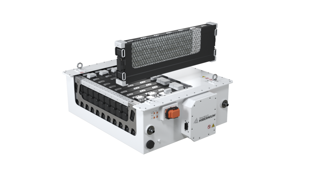
Xerotech’s batteries are built around Xerotherm, using a scalable and modular product architecture called Hibernium (a reference to Hibernia, Ireland’s name during Classical Latin times).
As Dr Flannery explains, “Off-highway vehicle operators are some of the biggest companies on Earth, but even they don’t need more than a few, say, well-drilling vehicles or asphalt-grating trucks. So engineering batteries for that market means hundreds of different pack sizes, which can’t benefit from high-volume production as automotive packs do.”
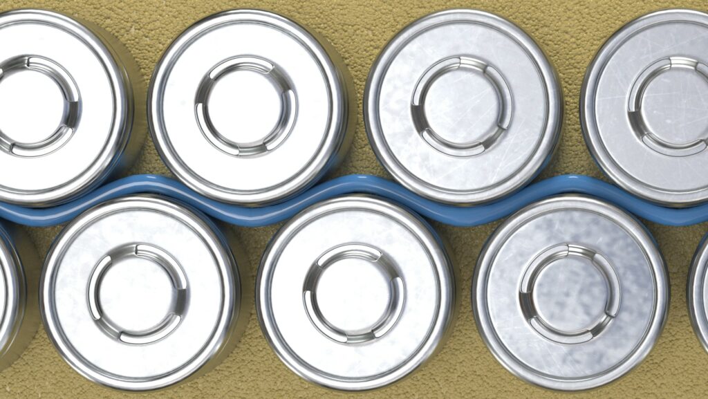
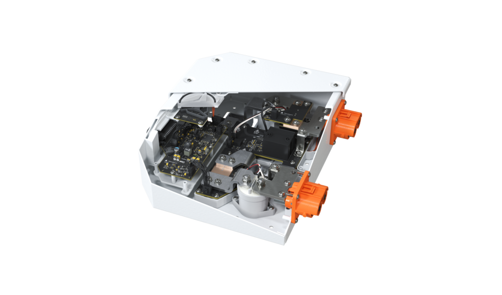
Within each Hibernium module, typically there are cylindrical cells and the Xerotherm system of sidewall cooling, which consists of liquid-inflatable ultra-thin plastic ducts. The cells and ducts are held within a structural, insulative and fire-retardant foam. The modules come in six sizes and can be stacked up to 24 in a pack, sitting side by side and directly connected to one another via busbars.
On the front of each pack sits Xerotech’s battery disconnect unit (BDU), which contains the BMS, contactors and related safety and control subsystems, along with connections from the BMS master unit to module-level slave BMS boards for lower-level monitoring and commands.
But given the need for hundreds of pack sizes and the consequent length of Xerotech’s product catalogue – at the time of writing, it covered 678 different packs, each with its own eight-page datasheet – citing the exact specs for every Hibernium pack is cumbersome.
To date, its largest with a published datasheet is a 290 kWh solution weighing 1429 kg and measuring 2392 x 1201 x 430 mm, with a nominal voltage output of 691 V (480 V minimum, 805 V peak). Its smallest is a 10.4 kWh pack weighing 104 kg and with dimensions of 561 x 511 x 430 mm, and designed for a 60-101 V output range (86 V nominal).
Xerotech also records and publishes huge amounts of data from in-house testing, including charge and discharge maps across 0-100% SoH and 0-100% SoC (graphed in increments of 5% at a time) and also across full temperature ranges as tested for regulatory compliance.
These are published for cell, module and pack-level characteristics. It is also making public its IP on its pack engineering and science, aiming for openness on par with IC engine manufacturers.
Why such technological transparency? One reason is to back up the claims made in its test data. But Xerotech also estimates that the wider EV battery industry’s guardedness about the contents and manufacturing of its packs results in timescales of 18 months on average for customers to receive initial units of a new pack, slowing electrification efforts. Transparency is therefore key to enabling Xerotech’s shorter lead times.

Cell technologies
Xerotech is agnostic regarding battery cell chemistries, partly in response to the rapidly changing nature of cell components and formulations. As Dr Flannery explains, “Cells have four key ingredients: anode, cathode, separator and electrolyte. Change any of those and you change the battery’s characteristics. What many people know as lithium-ion cells is actually a broad family, designated mostly by cathode, and NMC is the most widely used.
“But more cathodes are coming out, like LFMP [lithium iron manganese phosphate] or NMCA [nickel manganese cobalt aluminium]. And across the other ingredients there are new things like silicon anodes, inorganic electrolytes and ceramic separators, which could all significantly change cell characteristics like voltages, amp-hours, and thermal behaviours.”
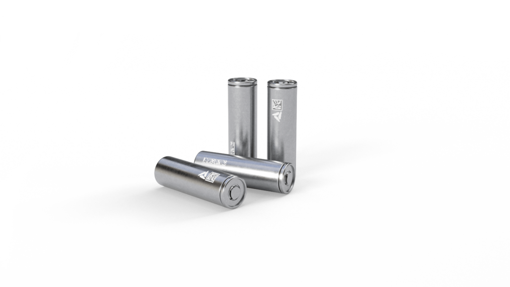
Xerotech therefore avoids sticking too closely to one cell chemistry or supplier. That said, the company exclusively uses 21700 (or 2170) cylindrical cells, which are 70 mm long, 21 mm in diameter, 70 g net weight and 5600 mAh maximum capacity.
“2170s are generally the most widely available cell for different chemistries,” Dr Flannery says. “They have their limitations, in that some future components like solid-state electrolytes or ceramic separators might not always be machine-wound well enough for cylindrical formats.
“Prismatic and pouch cells also generally have a longer cycle life, because they can use more viscous electrolytes as you don’t have to inject them into a tightly packed can. But cylindrical cells have the best robustness against thermal runaways thanks to their metal cell walls – prismatic and pouches just can’t match that.”
NMC, LFP and NCA cylindrical cells are the most common in Hibernium modules for their technological maturity and commercial availability. Given LFP’s often-touted safety benefits for risk-averse heavy industry operators, it might be assumed that LFP is inherently the best of these for off-highway, but Dr Flannery cautions against this.
“We’ve carried out a lot of safety testing to understand all the cells’ behaviours across all temperatures, SoH and SoC bands, all vibration and harshness conditions, and so on, and our BMS reacts accordingly with our thermal and electrical controls to give an equivalent level of safety whether it’s a pack built on LFP cells or the highest energy density NCA cells,” he says.
“Cells have different failure modes. For instance, you generally get less flame in a thermal runaway with LFP than other cathode chemistries, but a lot more gas, which can be even worse if you’re underground with significant hydrogen build-up. There, it could be better if the vented material’s burning so workers aren’t trapped underground with a gas build-up, or the ATEX-risk of a small hydrogen explosion.”
On examining the use case, Xerotech has found that heavy-duty off-highway work needs the maximum energy possible, owing to the sheer sizes of the vehicles and the heavy lifting required, making NMC chemistries optimal for most customers.

“Maybe that’s unique to us because of our thermal and safety technologies, but there’s a real lack of education in the industry as to what datasheet parameters mean in practice,” Dr Flannery remarks. “Should we supply someone with an LFP pack with 6000-8000 cycles, or a 40% more energy-dense NMC pack and then manage it for a smaller depth of discharge [DoD] window to achieve the same cycle life?
“In our view, OEMs will want either an energy pack, a power pack or a long cycle-life pack. And with new automotive standards requiring that smoke from a battery pack cannot enter the passenger compartment within 15 minutes of a thermal runaway being detected – which might increase in future – we’ll pick and foster whatever future cell innovations make sense for each of those requirements, along with alternatives for supply chain resilience. We think that’s how most of the market sees it as well.”
Among upcoming cell technologies, Xerotech is looking with anticipation at inorganic electrolytes and sodium-ion chemistries. The former does not flame (and Xerotech has announced a partnership with Innolith for its inorganic electrolyte cells), while the latter stands to bring down pack prices. It also expects to work with 4680 cylindrical cells, pending wider commercial availability and sufficient in-house testing to characterise their performance and safety.
Active thermal management
The Xerotherm system of ducts runs longitudinally between every other row of cells in the Hibernium modules. The ducts are made from ultra-thin plastic and inflate with water-glycol according to the BMS’ command signals to the coolant pump.
Xerotech says a key advantage of this versus typical sidewall cooling is the open and flexible nature of the duct, which means that the coolant pressure drop between the inlet and the outlet is an order of magnitude lower than that in normal sidewall cooling ribbons or cold plates.
That enables much higher flow rates than typical cooling systems, and hence more even temperature gradients across modules and packs, which in turn improves performance and lifetimes while reducing TCOs.
Dr Flannery also notes that conventional aluminium cooling plates use a lot of thermal interface materials (TIMs), which while more conductive than some other plastics have around 1/100th the conductivity of aluminium. That is partly down to the thickness of the TIM, which is a necessary evil for preventing the aluminium from shorting the battery cells.
“Skip the metal entirely and you save considerable weight, and if you use a plastic that’s incredibly thin, rather than the very thick TIM plastics, you maximise thermal conductivity, because thickness is the dominant factor in preventing heat transfer,” Dr Flannery says.
“And our ducts are also inflatable and pliable, so once they’re pressurised during assembly and in normal operation, they fill against the curved cylindrical cell walls for perfect angular contact with every cell in the pack. Achieving consistently close physical contact between coolant and cell is a key design challenge – even Tesla’s approach of glueing 4680 cells to an epoxied ‘bandolier’ has struggled to achieve that kind of contact in the Model 3, Y and Cybertruck packs.”
The ducts’ mechanically simple nature and close cell contact also make for an inherently open structure inside the modules. No ribs or multi-lumen tubing extrusions are needed, as with cooling systems based on metal pipes and cold plates; this contributes to the minimal pressure drop.

“The rate of pressure drop in conventional systems increases as a quintic function of coolant inlet and outlet sizing,” Dr Flannery comments. “Halve your orifice diameters and you can get 32x the pressure drop, so having an open structure is critical from a thermal management perspective.
“Your goal isn’t turbulent flow and high heat transfer, it’s a high flow rate with even heat transfer, so you hold the temperature across a pack within a 1ºC envelope for a given discharge rate. So maximising mass flow rate and minimising pumping head losses is what we believe to be the best design trade-off for a pack.”
The larger Hibernium packs therefore achieve water-glycol flow rates of up to 300 litres/minute, around 10 times that of comparable 290 kWh packs, owing to the minimal pressure drops of Xerotherm.
Xerotherm was originally inspired in about late 2017 by a computer anti-static bag, and Dr Flannery began prototyping it with flat polyester sheets, their edges welded lengthwise before being joined to additional plastic assemblies. Eventually, he and his team moved to a blown film extrusion process, a more conventional and technologically mature approach for making thin-film plastic ducts, and gradually optimised the material’s thickness, doping, welding and other qualities.
“Development has generally been experimentally led, but the entire cooling system has been replicated in CFD, where we’ve used a combination of tools to optimise the duct design,” Dr Flannery says.
“A lot of the original work was done in Ansys Fluent, with structural design simulated in Ansys Mechanical as well as Altair SimSolid. We’d validate that back against a great deal of physical testing, along with some 1D and 2D modelling in MATLAB Simulink as well as just straightforward spreadsheets.”
Fire and electrical safety
The structural, insulating and fire-retardant foam encapsulating the cells is a polyurethane that expands following extrusion, enabling wide volume filling with a material density equivalent to about 15% that of water, making it a low-weight solution.
“Potting compounds aren’t new to the battery industry – Tesla started it with their ‘blue goo’, a silicone that they fully potted the modules in,” Dr Flannery says. “But the disadvantage of those material types is their weight, and the structural pink foam in their Model 3 encasing their 4680 cells isn’t even fire-rated – it burns.
“Silicone cell encapsulants exhibit a similar density to water, and perhaps slightly greater weight. Furthermore, by their chemical nature they’re much more expensive than polyurethanes, as manufacturing them takes a much more complex and involved process. They also generate a lot more contaminants for production lines; you really don’t want silicone off-gassing and contaminating metal surfaces.”
Naturally the polyurethane is also chosen for its strong thermal insulation properties, which stem from the open but air-filled nature of its cellular structure, and help contain heat from passing between cells during normal operations as well as thermal runaways. It is also fire-retardant, and after extrusion into each module it is doped to minimise its capacity to burn.
On top of fires and thermal runaways, the safety of Hibernium’s high-voltage output has been another engineering focus for Xerotech. “It’s important to understand that all a battery can do in a fault condition is open its contactors,” Dr Flannery notes. “It can’t reduce power, and it has no control over the load demand it’s being subjected to.
“When you open an HV contactor under load, it’s a very energetic event. DC arc welding is about 10-30 V, so compare that to the 600-800 V, high-current output of an HV pack and you can maybe imagine how dangerous that is.”
Contactors can therefore open under load between one and five times before being effectively destroyed. Accordingly, to enable prudent servicing of the Hibernium contactors, Xerotech has designed a manual service disconnect (MSD) mechanism on the outside of the BDU for isolating the BDU from the rest of the pack and hence safe swapping of contactors (which it notes is otherwise very straightforward).
“Mechanically, the MSD breaks the power connections at the middle of the pack,” Dr Flannery says. “That temporarily reduces the voltage output by half, which is good from a fusing perspective and also means we can work freely on the BDU without needing any protective systems because the electrical system is completely dead.
“It also incorporates a high-voltage interlock loop [HVIL], as do all our HV connectors, and there’s also an active HVIL circuit that goes out to the broader system.”
As well as preventing high-voltage accidents, the MSD also enables untrained personnel to safely disconnect loads during accidents that can cause thermal events, such as fluids splashing or immersing the pack.
Other key electrical safety functions are embedded in the BMS. One is overcurrent protection, which is achieved via a dual-redundant shunt (one primary shunt, one secondary) for current monitoring, and pre-programmed current limits. At one of these, a warning is delivered to the driver-facing external system, and at an upper limit the BMS cuts off the power supply.
“Those BMS functions are pretty well-known and understood, but most commercially available MSDs are totally unusable for large, heavy-duty applications,” Dr Flannery cautions.
“In the MSD we’re using, the biggest fuse is 630 A, but the actual continuous current rating on the plug receptor is 300 A. That’s fine for general automotive as road EVs only exceed a few hundred amps in very short durations, but if you’re running a 300 kWh pack continuously, you’re likely to be pulling 500-700 A for 2 hours, so we’d be really interested in trying out an MSD in which all subcomponents are actually rated to handle those kinds of currents.
“The Gigavac system for hypercars is potentially interesting, but otherwise there’s a real gap in the EV market for someone to make a 1000 A-rated MSD for not just bigger stuff like construction and mining EVs, but even for high-performance, high-discharge road EVs like hypercars.”
If a cell should fail
Every cell has a coolant duct on one of its sides, and foam around all its others. The extent of encapsulation provides shock, NVH and penetration safety at the near-cell level, and importantly it can prevent heat propagation on a cell-by-cell basis.
“Containing failure to a single cell is the goal for us, and that strategy and target are additional reasons we’ve gone with cylindrical cells,” Dr Flannery comments. “Do a hotwire test on a large pouch or prismatic cell and you’ll see how violently and aggressively it fails. A 2170 cell has about 18 Wh of electrical energy inside, and a multiple higher when considering the chemical energy, while a large prismatic cell can go upwards of 1-2 kWh; the less energy per cell, the easier a failure is to contain.”
If a single-cell thermal runaway event should occur, the foam is sufficient in some cases to contain it to that cell, depending on the severity of the heat or flame produced, and will otherwise slow the spread of heat to its neighbours more than automotive-standard requirements on passive propagation resistance.
“And all the cells along a given busbar are connected in parallel. If you lose a cell, you’ll still read the same voltage,” Dr Flannery says. “You’ll have lost some capacity, and there’ll be a rupture in the cooling system, so it’s still end of life for the pack.
“But for aerospace, defence and other integrators who require their vehicles to be ‘fail-operational’ [designed to maintain normal operations in the event of a system failure] for a certain period, minimising or substantially slowing damage during catastrophic events like that is important. Thermal events will initiate for us as often as they do for our competitors using the same cells, but our internal module architecture will slow or contain those events far better than conventional approaches.
“For non-fail-operational operations though, we tell customers to get the pack out of the EV as quickly as possible and submerge it in water for a week to prevent re-ignition later on.”
Also, the coolant duct’s plastic melts and breaks apart at 100 ºC, causing the water-glycol to flow out, extinguish and drown any burning or off-gassing cell material.
“That passively enables either total fire suppression, or far more than 15 minutes of delay before smoke ingress into the passenger cabin,” Dr Flannery observes.
“The cell that fails will melt the duct precisely where it touches, and our tests have found that in most instances, the foam encapsulates both the cell and its nearest portion of the coolant duct well enough that water-glycol will flow in a contained way, around only the failing cell, and not any others.”
The water-glycol fills the tight space between the failing cell and its surrounding foam within a few seconds, creating a pressure equilibrium such that the liquid does not flood the entire module, negating the need for valves to shut off flows within a row or module of cells.
The module’s housing plastic is selected for being inexpensive, highly mouldable and a V-0 ABS. If burning, it self-quenches within 10 seconds, and no flaming debris drips off. Also, the foam encapsulant surrounding most cell walls helps prevent fire from touching the module enclosures to begin with.
The cells also have several mechanical safety features. Layers stacked inside the top cover include a positive temperature coefficient (PTC) device, a ring that, with rising heat, generates an increased resistance, limiting the current outflow and reducing the chances of an electrical fault.
Very near the PTC is a current interrupt device, which consists of two plates in the cell cover. During internal venting, the top plate bursts upwards inside the cover (as a passive mechanical response to high pressure, heat or overvoltage), breaking the electrical connection inside the cell.
Also, if a catastrophic impact should occur that risks an arcing event from the modules, the wire bonds from cell to busbar are designed to break, cutting all power connections across every module.
Xerotech integrates WL Gore’s PolyVent XL (also called PMF 200542) at the pack level to serve as a breathable membrane that maintains ambient air pressure inside the pack regardless of changes in outside pressure, for instance if the packs are driven up mountains or flown in aircraft. The company will also integrate and use separate burst discs for thermal runaway scenarios.
Module manufacturing
Production of Hibernium modules begins with manufacturing and assembling the structural components and the Xerotherm system, after which comes the installation of the cells, foam, wire bonds and covers, followed by pack assembly.
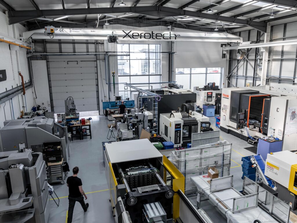
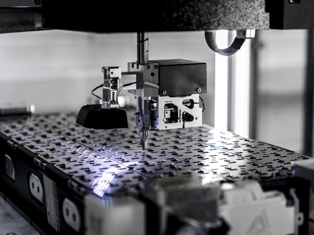
Xerotech’s manufacturing facilities contain injection-moulding systems, including a 100 t all-electric moulding machine, along with five-axis milling machines for CNC-cutting mould tools from metal billets; a spark erosion machine is also used for high-precision machining. Some additional r&d for jig fixtures also uses these machines.
One of the most critical injection-moulded plastic components is a ‘separator plate’, an ABS frame composed of circular slots, six slots long and 16 wide, for holding 96 cylindrical cells in place. That enables installations of cells in groups of 96 at a time in modules and packs.
Also injection-moulded are the module housing walls, coolant nozzles and MSD housings. There is also an eight-cavity metal mould tool used for forming the nozzles from ABS. As each module is 16 cells wide, eight ducts per module is standard, making for 16 nozzles (or two batches off of that mould) for each duct to have an inlet and an outlet.
Before injection moulding, solid plastic parts and some manufacturing jigs are prototyped in Xerotech’s additive manufacturing (AM) facility, where 20 Prusa i3 Mk3 fused deposition modelling (FDM) printers extrude plastic components for validation.
“It takes 6-12 weeks to make a mould tool, depending on its complexity, so AM is really useful for rapid prototyping,” Dr Flannery comments. “Some FDM printers we’ve used would skip layers or just break, but we’ve found the Prusa Mk3s have very good repeatability, and we’ll soon be buying a fleet of Bambu printers for prototyping parts in a V-0 ASA, which we’ll validate for potential safety gains.
“In future, we’ll also investigate how multi-jet fusion and selective laser sintering printers could make plastic parts that we might only need for a few bits per pack and are too geometrically complex for injection-moulding.”
Most of Xerotech’s proprietary machinery has been developed for manufacturing the coolant ducts, along with other plastic-related processes including joining plastic parts and assembling modules, along with processes requiring robotic or pneumatic machines. By analysing its production flows, the company periodically identifies bottlenecks and develops custom machines (or iterates existing ones) to reduce them.
“Something like finding the speed at which we weld two pieces of plastic together to be too slow will drive a requirement to eliminate the process or make a more robust machine,” Dr Flannery says.
“Less prioritised but still important is looking into potential cost savings from designing and building machines more tailored to our processes and components. We never outsource the building of one of our own machine designs, as we’ve found that’s far too expensive and requires transferring a substantial body of knowledge for the manufacturer to get it right.”
The coolant ducts begin life as plastic pellets that are shipped into Xerotech’s facility and blended with proprietary materials to achieve the correct plastic formulation. That compound is then extruded through a tube-shaped die, before being blown with air to produce the thin-film walls and long form of the duct.
After quality checks, the ducts are joined to the injection-moulded plastic nozzle subassemblies using proprietary heat welding processes optimised in-house over several iterations.
“Our current plastic-welding system is a fifth-generation machine, and is controlled precisely for timing, temperatures, pressure and geometries of the parts and the welding surfaces,” Dr Flannery says.
“We’ve even come up with our own quality checks to determine whether a weld is good or bad, because no-one else is working with something like our ducts and sub-assemblies. If you’re making a unique product and don’t make your own machines, it’s very hard to understand what you need to change to optimise your manufacturing throughput.”
After the plastic sub-assemblies and module housing parts are joined by welding and adhesives, the cells are slotted into the separator plates installed at the bottom of the module. With those bottom plates holding the cells’ bases, an upper separator plate is placed on top, so the cells are held in place at both ends.
Busbars and welding
Before this assembly stage, both separator plates will have been bolted to their module’s busbars, which are machine-cut in-house from sheet aluminium.
Hibernium’s busbars are cut as linear pieces that run the length of each module, with current cross-flowing across them. The cell power take-off points run along their sides as parallel connections, with the main power take-offs enabled through the L-shaped geometry of the bar, through which the busbars also serve as structural members for the modules.
“And we split these linear busbars down the middle, to give our two different voltage configurations: either 8S or 16S,” Dr Flannery says.
The cross-flowing nature of the current enables Xerotech to use the same standard aluminium as in most of its pack housings – AL 5254, rather than AL 1000, which others might use in their busbars – to enhance production simplicity and cost-effectiveness. It also enables high current densities in the modules, the company noting that its smallest module outputs around 1500 A continuously and 2000 A at peak.
“And that’s without using copper busbars or any special preparations,” Dr Flannery adds. “We can effectively redline a Molicel P45B, the highest power cell in the world, with 2000 A peak for 3-4 minutes, essentially discharging at 20C, which is probably double the power of eVTOL aircraft.
“Achieving those current flows is difficult with single-sided wire bonding and busbar configurations, as that gives a lot of pinch points on the current path, leading to localised heat generation and other problems.”
After an optical inspection for QC, the cells are joined to the busbars at both ends through ultrasonic wire bonding.
“That basically melts the micro-buses protruding from the aluminium bars to fix them to the cells,” Dr Flannery says. “Ultrasonic welding is quick, reliable and robust. It scuffs and abrades the oxide layers, so you don’t get intermetallic compounds forming at the interface, as with laser welding, and it’s cleaner than hot-plate welding.
“A wire bond intrinsically functions as a fuse on top of the cell, and it detaches easily in response to a crushing impact. All that said, we’ll probably switch to laser welding for our next-generation platform when we move to 4680 or similarly larger cylindrical cells, as it will mean higher throughput, and we’ll have a new busbar design that will need to be laser-welded in place.”
The ducts are then expanded with water to their operating volume, the force of which pushes the cells to bottom-out in their holders, rigidly locking them in place without adhesives or UV-curing glues. The cells can then be potted with their foam compound to lock the cells in place permanently while still ensuring the ducts have enough room for full contact and hence thermal transfer with the cell walls.
The polyurethane is a two-part foam, dispensed into the module by a dynamic mixer head. “It has the consistency of olive oil when injected, and it’s a self-levelling foam with delayed action, so it levels and spreads out through the box quickly before expanding into a foam structure,” Dr Flannery says.
He adds that Xerotech is also looking into new polyurethanes that will provide greater rigidity and density than the current foam, to enhance the structural integrity and thermal runaway performance in the Hibernium packs.
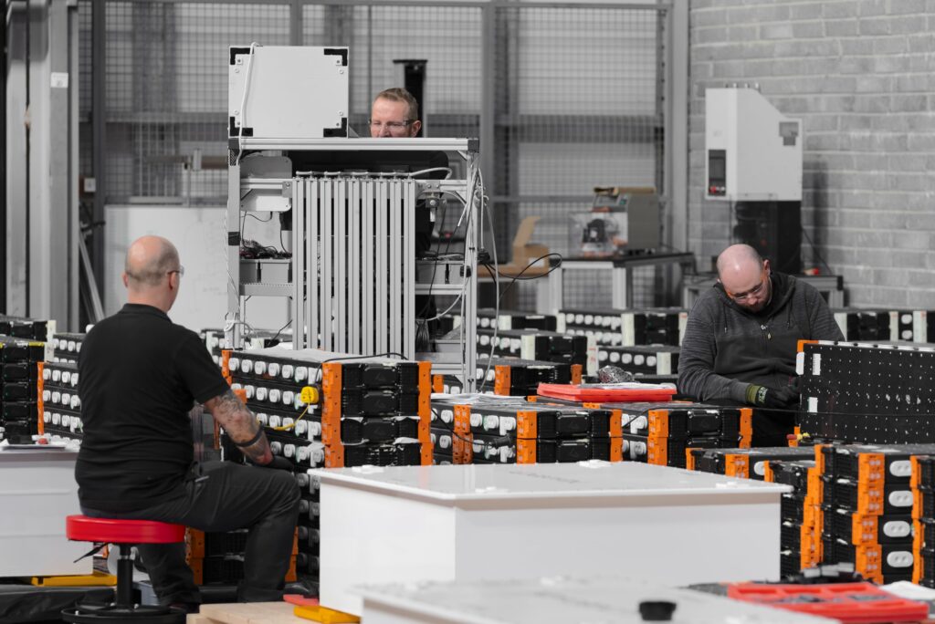
Pack assembly
Once the foam sets, the top and bottom module covers are installed and glued on, and the module is validated optically to confirm it is finished.
The required number of modules for a pack are stacked on top of each other and separated by silicone seals forming the fluid connectors between each module’s main coolant ports. Doing without plumbing harnesses helps with pack compactness, and optimises the cooling headers by ensuring sufficient water passage with low pressure drop.
“And our L-shaped busbars connect electrically and geometrically at the side, eliminating the need for wire harnesses inside and outside the modules,” Dr Flannery adds.
An outside ladder frame is then bolted onto the four corners of the module stack for rigidity, including a top piece for further protection.
The busbars are strapped about the sides of the module stack to electrically connect the modules in series, and then after some QC checks, the stack is lifted by an electric crane designed and built in-house, and lowered into a pack enclosure.
The sheet metal for the pack enclosures and busbars is cut in-house to allow flexible and fast supply of different pack sizes. “Take three Hibernium packs with 19, 20 and 21 modules, and all three will need different housing sizes and sheet metals,” Dr Flannery notes. “So battery manufacturers relying on third parties for sheet metal often find scalability stops at the pack level.”
A Trumpf TruFlow 4000 laser is among the laser-cutting machines in Xerotech’s sheet metal factory, although Dr Flannery anticipates moving to other production methods as volumes increase, including press tooling and turret punching machinery.
Once cut to size, the metal sheets are folded, formed and welded together to form enclosure sub-assemblies for packs and BDUs, after which they are painted in Xerotech’s signature white.
“Having all this in-house means that for critical projects, we can turn a production pack around from scratch in less than 16 hours, and as standard we offer customers a prototype lead time of about 4 to 5 weeks, compared with 3 to 6 months at absolute best for most pack manufacturers,” Dr Flannery says. “If we really push ourselves, we can make a prototype in 2 or 3 days, and working our own sheet metal is the biggest enabler of that.
“We expect our current facilities, once scaled up over the next 12 months, to have an initial capacity of 0.4 GWh of pack assembly; then the future facility we’re planning here in Ireland will be somewhere between 2 and 4 GWh, with a US facility to follow at some point.”
The pack enclosure typically comes as two aluminium pieces. One is a five-sided sub-frame that is folded, formed and welded to form the core box shape; the second is the lid, bolted on top. The BDU is normally also welded onto the pack housing’s front end, so its lid, also bolted on, can be considered a third piece.
“Other packs usually have big flange connections outside their boxes, but that means you then need to transfer loads from the stack, through the inside of the box, so you add a lot of structural membranes through the housing, which adds cost, complexity and weight,” Dr Flannery comments. “Bolting directly to the sub-frame instead makes for a compact housing that serves purely as an environmental bubble, not a structural one.”
Although most of the packs have been made from Al 5254 (with powder-coated paint), Xerotech’s standard-issue Hibernium enclosure is now steel, a change made to improve manufacturability and welding throughput – key factors in scalability, particularly regarding plans to move to robotic welding next year.
Steels also have higher melting points than aluminiums, meaning greater safety against thermal runaways. Xerotech will also consider steels, aluminium, and coatings on a case-by-case basis, given the potential for corrosion risks owing to paint failures.
“And bolting the pack and BDU lids means debonding and opening them for maintenance is very easy,” Dr Flannery says. “There is a dispensed adhesive seal, but it doesn’t get in the way, and although our housings are IP67-rated, we’re capable of IP69K and we’ll have that rating at some point.”
Testing and analysis
Once the module stack is lowered into its pack housing, end-of-line tests are carried out. These include load cycling, leak testing, isolation monitoring, cycles in test chambers across different temperatures and humidities, and external shock and vibration tests before it is packaged and shipped.
When validating a new pack design or configuration, key destructive testing includes nail penetration tests. “We’ll also detonate a cell in a module that’s sandwiched above and below by additional modules, to measure cross-module propagation,” Dr Flannery notes.
“In automotive EVs, there’s a low risk of cross-propagation because their modules typically sit apart on a flat, wide bed. But off-highway packs are more block-like because of how those vehicles are shaped, so it’s an important parameter for us to check.”
For validating lower-level systems, module tests on Xerotherm’s extinguishing capability start with using a wire around a cell in the middle of a module to heat that cell to failure. Once the cell goes into runaway, test instrumentation on fluid flow and temperature can sense the speed at which the adjacent duct melts and releases coolant onto the cell, half-a-second being the average time taken to release the water-glycol.
“We’ll often use the highest power and energy-density cells we can get to run those tests, to characterise the most extreme failures, and we’ll run them at multiple SoCs to see how energetic the reaction is at different levels, including the worst case scenario at 100%,” Dr Flannery says. “Even then, the module self-extinguishes within 20 seconds and the pack keeps working.”
In Xerotech’s cell testing lab, several racks of cell cyclers from Neware run endurance tests, each machine interfacing with eight cells at a time, with machines typically stacked in groups of eight per rack. Multiple different chemistries are tested simultaneously in each cycler, given that they all are 2170 cells and therefore compatible with the same machines, even if some are 4.9 Ah and others are next-generation 5.5 and 5.8 Ah cells.
Environmental cycling rigs in the cell testing lab run several hundred cells at the same time in individual chambers with liquid-cooled backplates. Those cool and heat the cells at different gradients (from -10 ºC to over 60 ºC) while running varying C-rate profiles, to characterise and map their operating behaviours. An environmental test chamber here enables further testing below -40 ºC.
“We’re at about 10% of our testing capacity now, but we’ll need to grow that capacity over the next few years to serve the range of cell technologies, customers and pack supply quantities we’re aiming for,” Dr Flannery says.
“Some of our cyclers are for long-term endurance cycling, and those only go up to 5 A or 1C discharge, but we have high-performance cyclers that go up to 30 A per channel and 5-6C. When we go up to 4680 cells, or make more use of high-power 2170s like Molicel’s products, we’ll use our biggest cyclers, which do 50-100 A per channel.”
Key standards followed for cell testing include UN 38.3, which Xerotech follows for every new cell type received, along with all the standard homologation tests even if the cell supplier claims compliance with them.
“We do long-term cycling of new cell types, running them for a year at different rates, dynamics, temperatures and gauge their behaviour across all SoCs and SoHs,” Dr Flannery comments. “We don’t need that for compliance, but we want to optimise the DoD, other configuration points, and warranties we make available to customers.”
Actual cell performance testing is relatively short, lasting around a month. It maps voltages, currents, direct current internal resistance and other parameters across time and states of charge, to better understand how the SoC and SoH can degrade over time and temperature, along with other key information for BMS inputs and timely control outputs.
“You’ll see all that in our datasheets. We give the full power map across different temperatures and C-rates and so on, because it’s fundamental for integrators looking to optimise their vehicle designs to know everything their battery can do,” Dr Flannery notes.
“And it saves us a huge amount of time and questions when customers come in, to have publicly available documentation that exposes all our testing results to them and contains all the answers.”
The machines for leak-testing Xerotherm ducts are designed and built on-site. Xerotech’s original leak-testing machines tested one duct at a time, but the present version tests eight at once automatically, incorporating repeatability and traceability gained through data over time.
A leak-test engineer first installs eight ducts – a complete batch for a Hibernium module – into the test machine’s nozzles, and presses a button to start its testing profile. At that point they are cycled with water-glycol while being scanned for leaks and traced for QC; the test takes 3 minutes.
Given the variety of tests and associated equipment, and the amount of data produced, Xerotech uses a range of COTS data acquisition systems, from National Instruments and similar organisations; LabView is used to set up data acquisition programs. Once acquired, the data is typically logged and graphed in .CSV and other Excel spreadsheets.
“Obviously, our CAE processes are more complicated than that,” Dr Flannery explains. “FEA and CFD simulations come with all sorts of Python-based workflows with pre- and post-processing of data to bring into our models, but the bulk of our data organisation rests on pretty simple tools, with quite a few back-ups for our cloud share points.
“And while we’re focused for now on just getting as much data as possible, we’ll be looking into new things we can do with that data in the future for safety, transparency and keeping our BMS algorithms optimised. That will include machine learning [ML], adaptive algorithms and cloud-based BMSs. ML is being used for degradation analyses and other useful insights, and our amount of battery data could interplay well with that.”
Traceability is vital throughout both testing and manufacturing, with barcodes and QR codes used across materials, duct manifold assemblies and some battery cells to track parts and trace bottlenecks or faults throughout workflows. While Xerotech is ISO 9001-rated, at the time of writing it was aiming for the IATF 16949 automotive certification standard, meaning full traceability throughout production.
Battery management
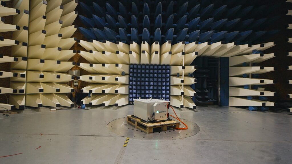
Developing the BMS started with defining the system concept in terms of core functions and features, after which the circuit boards and physical layout could be designed. Validations of those designs followed, with tests for EMC, shock, vibration, overvoltage, undervoltage, and temperature from -20 ºC to +50 ºC then being run.
After verifying the hardware, software development began. It consisted primarily of writing lower-level base software (BSW) such as firmware drivers, and application software for higher-level functions including all the customer-facing features; the BSW architecture has been designed to make it transferable between BMSs and abstracted away from the hardware layer.
The BMS architecture consists of a centralised master BMS inside the BDU and distributed slave BMS units installed at each module, with CAN J1939 connections linking them to the master. The centralised battery management architecture serves the scalable, modular pack design architecture vital to Xerotech’s off-highway customer base.
Each slave BMS mounted at the end of each module reads cell voltages and temperatures, using a Texas Instruments (TI) BQ79616 as monitor chip, which comes designed for tracking up to 16 series of cells; it therefore works for both the 8S and 16S module configurations. It can also withstand temperatures from -10 ºC to +125 ºC, potentially enabling continued operation during thermal events.
“For redundancy, the slave BMS measures four temperature sensors per module, and that’s specifically at the discharge point, which is always either the hottest or coldest point, depending on whether you’re heating or cooling the pack,” Dr Flannery says.
“Meanwhile, our high coolant flows ensure even temperatures across our modules, and the slave BMS chips communicate with each other over a daisy-chain SPI interface. That has a ring architecture for bidirectional and hence redundant comms; if there’s a break on one side, the data signals can run and be read around the other way.”
Over and undercurrent conditions are read by the master BMS, which tracks the shunts to do so while communicating with the slave chips. The master’s gateway chip is a TI BQ79600, which in turn communicates with the BDU’s central microcontroller, a TI TMS570, one of Texas’ safety-critical transportation MCUs designed for ASIL ratings in system design. It is powered by a 160 MHz ARM Cortex R4F CPU, and comes with 2 Mbytes of flash memory and 160 kbytes of RAM, both with ECC.
“Getting the hardware layer and the BSW to work was quite complicated,” Dr Flannery says. “The daisy-chain bus for instance was challenging, we ran into quite a few edge cases but worked with TI to solve them.
“We’ve designed our BMS for compliance with ASIL-C, and that drives a lot of the key design requirements inside. Both current shunts are isolated components rated at up to 1000 A each. We also have an isolation monitoring circuit continuously checking both the HV+ and HV- to ground, making sure there’s no leakage or other connection issues, and a pre-charge contactor and resistor for initial power up.”
Inside the BDU is also a triple-axis accelerometer and gyroscope for measuring shock and vibration during operations, principally to acquire data for understanding customer applications, but also for detecting crashes. An onboard SD card logs data from that and the BMS’ components to monitor for abuse conditions relevant to warranty compliance.
Lastly, a board for operating warning LEDs is installed and programmed for flashing short fault codes to operators, technicians and nearby workers, to avoid the need for reading complex diagnostics reports in the field.
“That sounds rudimentary, but it’s a hugely undervalued thing to put into battery packs. It’s actually helped us a lot in field tests and operations,” Dr Flannery notes.
Future prospects
Standards for road EVs such as ISO 26262 have informed the software and hardware development for the BMS, and upcoming regulations for off-highway vehicles will inform Xerotech if any further changes are needed for functional safety compliance, as will any changes in the years ahead, as safety requirements become clearer with more off-highway EVs being used.
With almost all the major names in off-highway and mining now looking into electrification, and trialling bespoke battery designs in either serial or pre-serial production, demand for battery packs is expected to ramp up in the years ahead. To meet that demand, Xerotech plans initially to keep scaling its site at Claregalway, effectively using it as a prototype factory for 400 MWh worth of Hibernium packs per year, as mentioned, after which a facility nearby is prospectively planned for outputting 2 GWh/year initially and up to 4 GWh/year once fully scaled.
“And after that, around 2026, we aim to have a location in the US, of a similar size and scale to the larger Ireland facility we’re planning,” Dr Flannery says. “Production will accelerate once we’re confident we’ve optimised our manufacturing and testing flows.”
Come the first quarter of 2025, Xerotech also plans to have its next-generation packs designed and in volume production. While off-highway electrification will remain its primary market, those new packs will include units designed for lower-cost, on-highway integrations such as trucks and buses.
Click here to read the latest issue of E-Mobility Engineering.
Some key suppliers
Processors: Texas Instruments
Connectors: Amphenol
Industrial adhesives: HB Fuller
21700 cylindrical cells: Molicel
21700 cylindrical cells: various
Inorganic electrolyte cells: Innolith
Vents: WL Gore
CFD: Ansys
Battery test cyclers: Neware
Temperature test chambers: Weiss Technik
Coordinate measuring machines: Aberlink
Additional measuring equipment: Insize
Additive printers: Prusa
Additive printers: Bambu
Injection moulding machines: FANUC
CNC milling machines: Z-MaT
CNC control and automation solutions: Mazak
Laser cutting machines: Trumpf
ONLINE PARTNERS

