


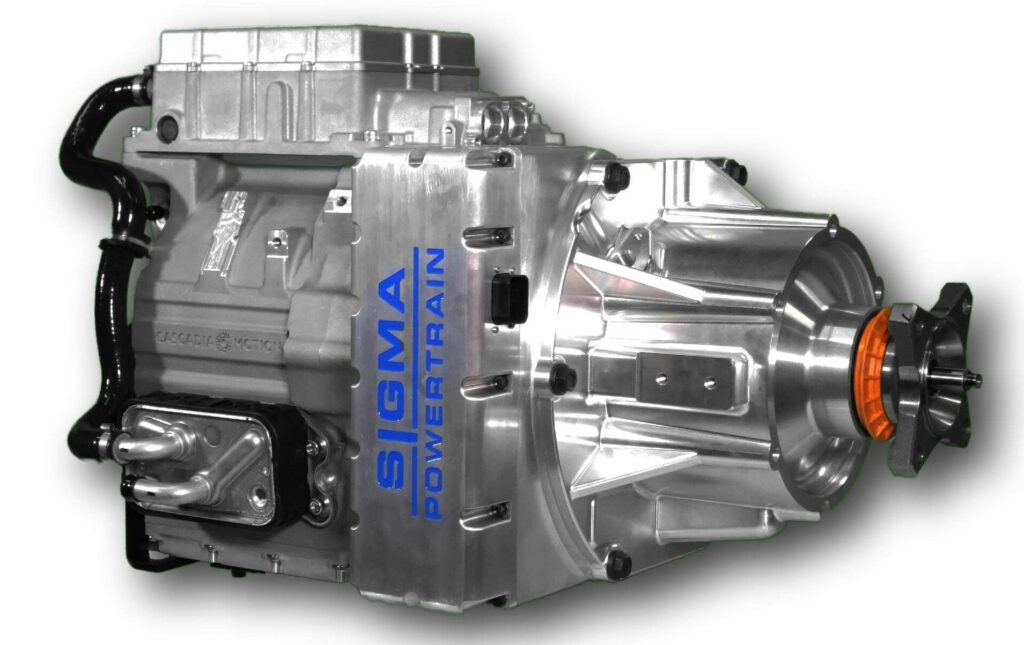
Sigma Powertrain EMAX transmission
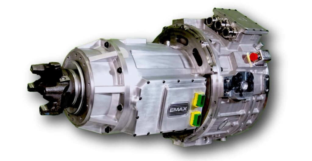
(Images courtesy of SPT)
For the common good
Rory Jackson explains how this modular all-electric gearbox can combine two motors to drive any size and weight of EV
High-voltage electric motors produce torque across a wide range of their rpm bands, enabling most electric cars on the road these days to achieve reasonably high power efficiencies with single-speed gear reductions. However, as discussed with David Hudson at ePropelled (see page 16), a more efficient kind of powertrain is needed if the world is to switch to all-electric propulsion.
That is because current e-motors suffer losses outside their peak efficiency spot, particularly at their top speed and maximum torque outputs, where the drops can be 10-25%. They also rarely generate enough torque at low speeds for any significant controllability or launching power, especially for heavy commercial EVs such as cement trucks, city buses and so on. These issues create the potential for wasting considerable battery energy and in the longer term place unnecessary burdens on maintenance technicians and national grids.
Some EV makers try to compensate by relying on one very large, heavy e-motor and a single reduction, but as has been shown by companies such as Designwerk (in EME 8, Winter 2020), using multiple small motors in combination via a gearbox will match the power output of one big one, while also weighing and costing much less.
Clearly, gearboxes can improve weight, energy and cost efficiencies by allowing EVs to use smaller motors, and by shifting gears to create a much broader peak operating zone – as they do in IC-engined vehicles – across their drive cycles.
Choosing the right gearbox is key to optimising a powertrain’s efficiency. For instance, using traditional, analogue-controlled geartrains makes little sense given that EVs are sold increasingly to commercial fleet owners on the promise of greatly reduced noise, parts counts and potential points of failure compared with IC powertrains. Also, automated manual transmissions (among other automatic and semi-automatic types of transmission) suffer parasitic losses from their hydraulic actuation systems that cancel out their actual efficiency gains.
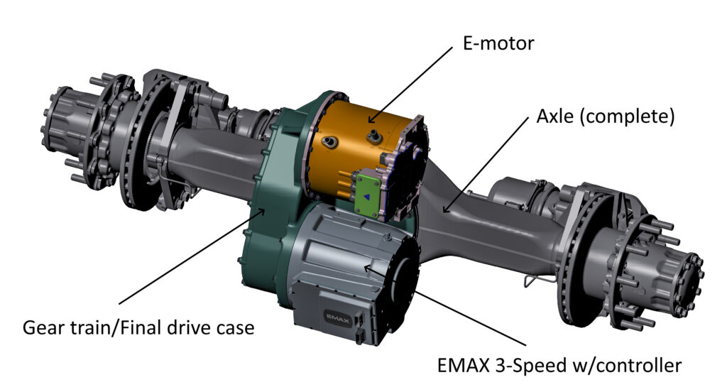
Seeking to resolve these drawbacks is Michigan-based Sigma Powertrain (SPT). Its patented EMAX transmission is designed principally to integrate two electric motors of any size and combine their power through an all-electric four-speed gearbox.
The gearbox measures 18 in (45.7 cm) long, and forgoes hydraulics and mechanical control levers. All the actuation is electric, and controlled electronically, with parasitic losses and noise minimised by careful selection of gears, shafts and electrical components. It is cylindrically shaped with an input port on one side (where one or two motors can be mounted axially, one after the other) and an output shaft on the other.
With its flexibility regarding e-motors, the powertrain can be modularly adapted to any size and weight of EV, but SPT sees Class 6-8 vehicles as gaining the highest improvements, with potentially 15% higher energy efficiency across their drive cycles compared with the next best powertrains, and shifting times of 250-500 ms with minimal torque interruptions.
Background
Sigma Powertrain was formed in 2016 to explore applications for an electrically controllable EV powertrain clutch technology invented and patented by John Kimes (founder and CEO of Sigma) and his team.
Kimes had been mulling over the concept for an all-electric transmission during his days at the Ford Motor Company, after seeing the DPS6 dual-clutch automatic transmission from Getrag (now Magna PT) and the 10% fuel economy gains it produced in Ford vehicles such as the Fiesta and Transit.
“Automatic hydraulic transmissions like those are great for smooth and power-dense gearshifts, but they nonetheless pay a tremendous price in parasitic losses in power, across their torque converters, friction clutches, high-pressure oil pumps and so on,” Kimes explains. “Getrag answered the question of how to turn a manual transmission into an automatic to improve fuel economy – parasitic losses – so I determined that the key to making an automatic architecture with the much lower parasitic losses typical of a manual was getting rid of the hydraulics.”
The resulting concept was a step-ratio transmission with no hydraulics, but the missing piece of the puzzle was electrically controllable clutches, which had not yet been invented. In the meantime, however, that inspired Kimes to invent the rocker clutch, a passive one-way clutch, that would become key later on.
Further inspiration came in 2013 after Kimes reviewed the dual-motor arrangement of Tesla’s S and X models, and determined that there had to be ways to improve their efficiency.
“Other early projects indicated to us that the larger the vehicle, the greater the need for a multi-ratio gearbox,” Kimes says. “Although the industry wasn’t quite there yet, it was obvious to us that it would get there eventually, so we formed Sigma to develop the powertrains that these future commercial EVs would need.”
EMAX development
“We started developing the EMAX’s power flow concept in earnest in 2013, to squeeze more efficiency out of electric powertrains already incorporating multiple traction motors,” Kimes says. “Early modelling suggested that by adding a summing gearset with the ability to change ratio, we could provide significant efficiency gains to larger classes of vehicles.”
The concept design evolved over the subsequent five years, while Kimes and his team pursued development of the electric clutch technology required to make their concept a reality.
In 2015, during a three-speed gearbox project for Mahindra’s North American division, sufficient lessons and supply chains were established to start developing and commercialising SPT’s all-electric powertrain concept.
Repeated iterations were performed during the early concept stages, with a strong focus on developing the technology around the components, so that when the EMAX’s design was being finalised, much of the work was a simple matter of putting the pieces together.
Kimes explains, “Early on, we relied heavily on drive cycle simulation using the Advisor software program to decide our general direction. Then we developed our own internal powertrain simulation tools to integrate motor efficiency data and provide optimisation knobs for improving the powertrain’s performance and efficiency.”
In 2019, feeling confident that the (now patented) clutch technology was sufficiently mature, SPT began building the first EMAX prototypes. It then engaged a full-time staff of software engineers to develop the controls, interfaces and simulations necessary for operating and testing the transmission.
Prototypes were then tested on SPT’s custom-built electric powertrain dynamometer. This is a test stand featuring battery emulation and full vehicle simulation capabilities for hardware-in-the-loop testing, which was key to controls development and tuning as well as hardware testing.
“Finally, our Raptor EVolved demonstration vehicle [see sidebar] has been our field test platform for the powertrain in application,” Kimes adds. “While not necessarily the target vehicle, the process of marrying powertrain to vehicle has provided significant insight into what is required to tune the powertrain for smooth and efficient operation.”
Operating modes
The outermost of the two motors (referred to henceforth as motor A) is typically integrated with three gear settings, with torque ratios of 3.63:1 in first gear, 1.72:1 in second and 1:1 in third. The inner motor (motor B) has two: 2.64:1 in first and 1:1 in second.
These shifts combine to give EMAX’s end-users four driving modes, which SPT calls A1B1, A1B2, A2B2 and A3B2, where A# refers to the A motor’s gear and B# is that of motor B.
A1B1 is intended as a heavy launch gear for starting loads or reverse. A1B2 provides a light throttle, and is also useful for launching. A2B2 meanwhile is a midrange gear setting, and A3B2 is for highway speeds.
“The control software sets the torque level of the A and B motors with respect to vehicle speed, requested torque and to whichever one of the four ratios the gearbox is in,” Kimes says. “That not only meets the torque demand of the driver, but does so at the maximum system efficiency with respect to potential losses in the inverters, motors and the mechanical power flow path through the gearbox.
“We’re able to call it a CVT [continuous variable torque], the reason being that in any of the four modes we can vary the torque from each motor to satisfy torque demand while maintaining maximum system efficiency.
“When motor B is changing gear ratio, motor A continues to send power to the output shaft. And when motor A changes ratio, motor B continues acting on the output. So our controller works to have each motor compensate for the other during shifting, to ensure torque interruptions are minimal as power is transferred.”
He adds that the EMAX architecture can also work by integrating just a single motor to create a three-speed, for vehicles that require highly efficient all-electric gearshifting but without a second motor.
Input motors
While SPT is agnostic to motors, it typically selects units from BorgWarner, particularly those from its North American subsidiary Cascadia Motion, and the TM4 Sumo family of motors from Dana. Most prospective customers currently request single-motor, three-speed powertrains, for which they can use COTS motor solutions but with some customisation needed for integrating them into a two-motor system.
For example, in the case of the DS HVH250 from Cascadia Motion used in the demo vehicle, SPT typically installs an auxiliary electric pump for further liquid cooling on top of the integrated oil pump that Cascadia includes with the system.
That system packages two BorgWarner HVH250 motors. The HVH250 is rated to a top speed of 11000 rpm, a peak (60 second) power output of roughly 350 kW, and a start-up torque of about 425 Nm with a weight of 57.2 kg. When packaged together in the DS HVH250, total weight is 106 kg, peak torque is 960 Nm, and top power output is slightly above 780 kW.
Kimes adds, “Continuous power density in electric motors is all about heat rejection. We focus on that and add auxiliary thermal management; state-of-the-art efficiency demands a dual active cooling system.
“Any time we get a request for a powertrain, we input the customer’s vehicle specs and operating requirements into a spreadsheet that very quickly sizes the required motor and axle ratio for the application.”
Electromechanical clutches
Kimes explains that the EMAX’s gearbox features two kinds of clutch for latching or un-latching the two electric motors to the powertrain. The first are reaction/static clutches, also known as brake clutches, in which the clutch locks the controlled component (typically a carrier, a sun gear or a ring gear) to ground. These types of clutches have one race permanently grounded, while the other race is attached to the controlled component.
The other kind is an input/dynamic clutch, where both races of the clutch rotate. These types usually connect input power to a component in a gearset. They are also useful when applied as disconnect clutches in wheels.
For its static clutches used in first and second gears, SPT uses the rocker clutch, a radial one-way clutch also found in Ford products. (Kimes invented it as a technical specialist at Ford.)
“At SPT, we’ve modified the profile of the locking elements, and added electromechanical actuation to them,” Kimes notes. “We then package locking elements for the controllable one-way clutch in both directions of rotation, to turn them into two-way controllable clutches.”
SPT has different variants of these clutches. Using the nomenclature of 11/00 indicates a two-way clutch that locks into both the power ‘on’ mode and direction of rotation, as well as into the opposite, regenerative direction of rotation. The ‘11’ signifies ‘one-one’ for power-on in traction and regeneration, and also that it can rotate freely in both directions without generating power; ‘00’ signifies ‘zero-zero’.
Kimes comments, “That is the same functionality as a dog clutch, but our clutches require much less force to change state. We have another variant that is 11/10/01/00, a four-state clutch that can be locked in both directions, or as a one-way clutch functioning in either direction, or be completely off.
“That allows heavy EVs to have functions such as hill-holding, where half the clutch is ‘on’ and the other half is ‘off’, or parking where both sides of the clutch are ‘on’.”
Engagement of the bidirectional rocker clutches is typically achieved using a pair of electrically actuated solenoids installed inside the electronics box next to the ECU. Each solenoid acts on one rocker, which locks the controlled element in one direction of rotation.
“If the torque capacity needs to be higher than a single strut and rocker can supply, we’ll install multiple rockers,” Kimes says. “This is known as dual or triple engaging, where two or three rockers respectively run radially in each direction to hold torque.”
For its dynamic clutches used in third gear, the EMAX uses a second type of electromechanical device: linear servo-actuators. When one such actuator’s motor is powered, it pushes forwards on a ring of plunger-like cams, which feature an arrow-head shape on their front ends.
The cams are inserted under the locking element to push the rockers into their ‘on’ positions, acting in a similar way to the cam on a parking pawl rod.
“Generally we’ll use the linear servo-actuated banks of plungers in clutches that have just two states – that is, the 11/00 type,” Kimes says. “But the 11/10/01/00 function can also be achieved by using two sets of linear motors and cams, where one motor controls a bank of plungers that lock the clutch in the power ‘on’ direction and the other motor locks it in the regeneration direction.”
The linear motor clutch consists of a stator ring which is grounded and an actuator ring which is hard-connected to one of the clutch races. The race can be permanently grounded, or it can rotate. The interface between the stator and actuator is agnostic to rotation, which notably makes the system agnostic to whether the clutch is dynamic or static, with a constant air gap between stator and actuator in either case.
“The function of our linear motor clutches is analogous to dog clutches using a shift fork, but in our case there is no mechanical linkage, only an electromagnetic linkage,” Kimes says. “With our actuator configuration there are no extraneous linkages from a shift fork going to an external electric motor or worm screw; we are packaged completely inside the case.
“Equally important, these magnetically latching clutches also have extremely low parasitic losses. The only power consumed with them is the <200 ms electric pulse that turns the clutch ‘on’ or ‘off’. Once in state, the clutch is kept there by a very strong permanent magnet latch in both the on and off states.
Gearshift transmissions
Each of the EMAX powertrain’s modes uses a different transmission sequence (the key parts of which are laid out in the ‘EMAX anatomy’ sidebar) and combination of clutch activations in order to yield the desired re-optimisation of output torque and speed. What follows is a description of each gearshift (the diagram above/below can be used as a reference layout to differentiate between the clutches).
In first gear (A1B1), clutches B3 and C234 are disengaged, and B12 and C14 are activated. As a result, motor B is coupled to (and therefore driving) the first sun gear. The B12 clutch is used to ground the first carrier and the second ring gear to the housing (through the notch plate), while B3 is left open to ensure that the first sun gear can move freely.

Motor A directly supplies torque to the second sun gear while motor B supplies an equal torque in the reverse direction of rotation to the first sun gear. Cumulatively, this results in an output torque ratio of about 6.2:1. The output torque = TA(RA) + TB(RB), so assuming equal torques in both motors’ yields, output torque = motor torque x (3.63 + 2.64) or 6.12 x motor torque.
In second gear (A1B2), the B12 clutch is engaged and the B3 clutch is deactivated (the brake clutches remain as in first gear), Motor B is directed to the output shaft via clutch C234 being activated and C14 being deactivated. Motor B changes direction and at a 1:1 ratio, while motor A remains at a 3.63 ratio. That means an output torque ratio of 4.63:1.
For third gear (A2B2), brake clutch B12 disengages and brake clutch B3 locks, while the two main clutches continue as in second gear, for a 2.72:1 torque output.
Shifting to fourth gear (A3B2) engages both dynamic clutches C234 and C14 and disengages both brakes. In this state, motor B applies torque to the first sun gear and to the output shaft via the first ring gear and the second carrier; none of the rotating parts are grounded to the housing. Motor A is also locked in a 1:1 state. That means an output torque ratio of 2:1 – the output torque is the exact sum of both motors’ input torque values.
In addition to the four driving gear modes, further shifting is performed to achieve the Reverse, Park, and Hill Hold gears.
For reverse gear, the clutches and brakes work identically to first gear, but the motors deliver torque in their reversed directions, giving 6.2:1 torque with the output shaft spinning in the opposite direction to first.
For Park, both brakes are activated, grounding all moveable transmission components and preventing the EV from moving.
In Hill Hold, as the EV is parked on a hill, one side of the second gear clutch is engaged and the other is inactive. Which one engages depends on which gear the vehicle is in, to ensure the correct direction of holding. Hill Hold thereby prevents rolling backwards while in first gear and forward while in reverse, regardless of slope.
ECU
Management of the powertrain comes from a patented ECU that consists primarily of two microcontrollers: a main microprocessor unit (MPU) and a safety MPU, connected for redundancy and hence functional safety.
Both MPUs are produced by STMicroelectronics: the main MPU is an STM32F413ZHTx, and the safety MPU is an STM32F413RHTx. Each system is built around a 100 MHz ARM Cortex-M4 core, with 320 kbytes of RAM and 1 Mbyte of ROM.
The main MPU primarily monitors the different speeds of parts across the entire transmission, to ensure shifting and traction are being executed normally, without parts slipping or becoming unsynchronised, even if a driver mistakenly switches back and forth between modes in rapid succession.
Six independently controllable H-bridge circuits run to the clutch actuators and are actively managed by the safety MPU. One or two of them can be configured for controlling additional components – for example, SPT is considering adding an oil pump for some future applications that might need further lubrication and cooling at the bearings.
SPT’s software manager Dan Knieper explains, “Every clutch has an embedded speed sensor that monitors the differential speed across the races. When a threshold speed differential is realised – such as 50 rpm for static clutches or 100 rpm for dynamic clutches – the safety MPU turns off the H-bridge to the actuator controlling that clutch. This ensures no clutch is set to ‘on’ in a potentially damaging, non-synchronised state.
“There are also position sensors on each static rocker clutch rocker that report back the state of the rockers in the clutch [as mechanically ‘on’ or ‘off’]. This data is used in our Park algorithm, our Hill Hold algorithms, and our gearshifting algorithms.”
Kimes notes here that the position sensors, from Magnetic Sensing Solutions, are highly desensitised to magnetic field interference – a critical capability for ensuring they are safe for high-power commercial EVs.
When the driver requests a particular gearshift or mode change, the main MPU receives the command input (from the EV’s VCU, for example) and decides when the time is right to fire or release the relevant clutches based on measurement inputs from the position and speed sensors. It also determines the ideal power delivery (and how it is split) from the inverters to the two e-motors to achieve the road speed or acceleration requested from the driver’s pedal.
“The safety MPU is enabling and disabling H-bridges almost all the time,” Knieper adds. “For instance, if the driver wants to shift from first to second gear, the ECU needs to shut off the first gear clutch, and control motors A and motor B to synchronise with the second gear before allowing it to fire.”
Also, since the solenoids and linear actuators are current-controlled, the main MPU calculates the correct duty cycle percentage in order to execute the shift to completion without consuming excess or insufficient current.
“The EMAX’s subsystems communicate over two CAN networks, one of which is a powertrain CAN bus running between the inverters for control of the traction motors, and the other is a vehicle interface bus,” Knieper says.
“That provides the human-machine interface, carrying commands from the EV’s pedals and shift lever through to the powertrain, and sends back status updates to the vehicle to tell the driver which gear they’re in, the position of the accelerator pedal, whether they are braking, regeneration, or the status of Park brake or Hill Hold modes. Really, anything the driver wants to be aware of can be delivered over that second CAN.”
The MPUs are integrated into both networks via independent transceivers in the ECU, in order to manage the inverters as well as the electrical actuators. Information on the performance of the motors and inverters is delivered to the MPUs via the powertrain CAN.
“We also have an extended bank of capacitors, as our actuators are high-current devices, running at 48 V and up to 30 A at their peak,” Knieper says. “The peaks last only for up to 150 ms when we’re firing the clutches, and at all other times we’re using little more than what is needed for running the MPUs, but the peaks are still enough to merit having those caps there to store the excess power and avoid stressing the electrical system.”
The software and algorithms are currently proprietary, although SPT has filed for patents on them, including protections for additional algorithms written with safety countermeasures covering NVH and functional safety. While ISO 26262 is not a commercial vehicle standard, both the control hardware and software have been developed with these specifications in mind in case SPT ever has to obtain that level of certification.
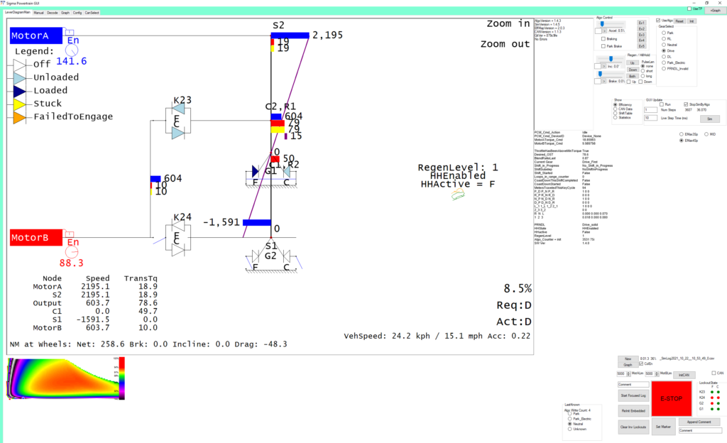
Before cutting any metal for the EMAX prototypes, Knieper and his team custom-built a GUI for simulating the physics of the transmission, initially using input parameters from the Raptor EVolved test vehicle. It was in this simulator that the control algorithms for smooth gear shifting, safety, Hill Hold, motor control and so on (as well as propulsion mappings such as accelerator pedal to output torque) were developed.
“The GUI consists of four major components,” Knieper says. “The first is the simulator, which displays a powertrain lever diagram to show us everything that’s going on, with an output rate of 10 ms steps so enable precise diagnostics and debugging. It allows us to confirm the control logic long before we have a transmission in hand.
“Second, we have a dynamometer control interface, as we wanted to use that same GUI for operating our 450 kW load motor simulator – which we can also use to simulate inclines, hard braking and other things on EMAX systems that are key for programming challenging shifts such as going from Park to Drive. The interface in this mode also provides driver inputs to the powertrain, such as accelerator pedal position and the desired drive mode.”
The GUI’s third mode is as a data collector, and the fourth is a data analysis tool for graphing and studying the flows of inputs, processes and outputs step by step, against time and the locations of simulated events across the powertrain.
With these tools, SPT’s software engineers spent several months writing the algorithms in C#, all the while following a number of core rules Knieper laid out to ensure they could be exported to Embedded C with high fidelity (and subsequently stepped through in the simulator with minimal stress in the event that any bugs were found).
“Some unique communications work was needed in the embedded control system too,” Knieper adds. “For example, we wanted to get the Embedded C algorithms to interact seamlessly with the CAN, and the H-bridge control algorithm was all written to optimise how smoothly we can ramp up the current when firing the clutches on or off.”
Future plans
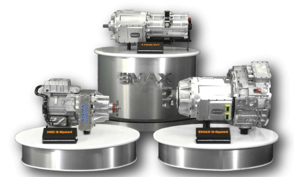
As well as being a motors integrator, SPT is widening its focus on efficiency beyond the EMAX and MID-Series (see sidebar ) into motors themselves. Its newest project, the SPT500, is an AC induction motor designed in-house principally to be packaged into the EMAX, to provide turnkey electric powertrains for central drive and e-axle systems.
Most recently, SPT has also designed an axle-mounted version of the EMAX (called the EMAXle) for customers manufacturing heavy trucks to run on e-axles. Prototypes of it will follow in the near future.
Kimes observes that electric propulsion demand across North America is split roughly three ways: between central drives, e-axles and in-wheel e-motors. As a consequence, SPT anticipates that this region might be the last to take up its e-propulsion solutions, although demand for new powertrains is picking up rapidly among American EV OEMs.
EMAX anatomy
Assuming a two-motor solution is requested, the customer’s choice of two electric motors (and inverters, if these are packaged with the motors) directly sit on the input side of the EMAX powertrain.
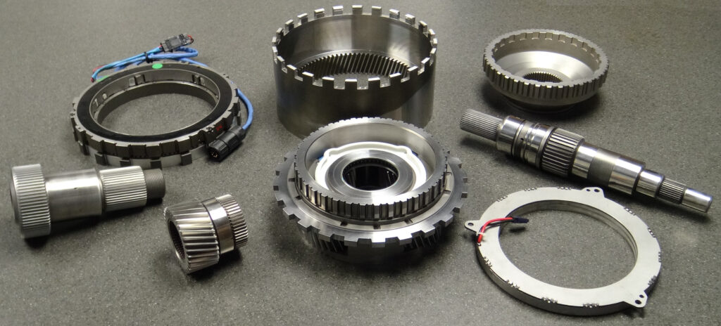
Various components are used to transmit and multiply the input torque from both motors at the back of the EMAX to a single output shaft at the front. These include numerous fasteners and fittings, a total of 12 bearings, a dynamic gear assembly and a static gear assembly. While many of them are installed in the powertrain by hand, the static gear assembly weighs 68 kg and is therefore lifted and lowered into each system’s enclosure by crane (after being built separately and held together by snap rings).
The enclosure is roughly 0.25 in thick, and is typically cast from A390 aluminium alloy for strength and machineability. On the side of it is an electronics box containing two electromechanical solenoids and two microcontrollers.
Integrating the components into the housing starts at the motor input side. First is the assembly responsible for third gear, which consists of a stator assembly, then a dynamic clutch assembly and a notch plate. This plate is made from a toothed ring, sintered to shape using powdered metals, and a hub, which is forged, before being sinter-brazed to the ring in a furnace (ensuring a joint stronger than its parent materials).
The stator is fastened to the housing, while the dynamic clutch assembly largely sits freely until engaged with the notch plate, which sits on a bearing that is integral with the dynamic clutch assembly.
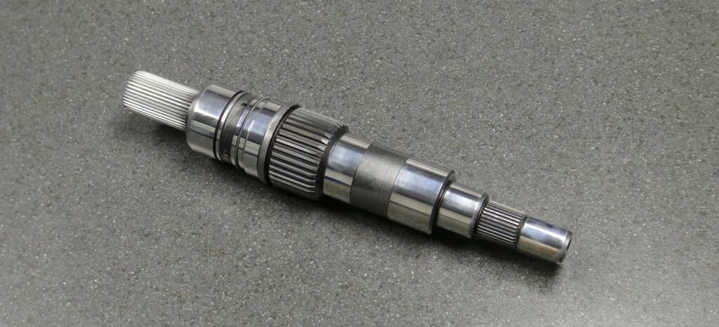
Installed after these is an input shaft made from carburised 8620 steel, which is driven by motor A, with the clutches acting separately on this shaft to put motor A into first, second and third gears. Motor B drives a secondary ‘input shaft’, essentially a pocket plate installed coaxially around the input shaft and inside the notch plate.
To mate the motors with their respective input shafts, the motors are configured with output shafts that extend into the EMAX housing via radial bearings, secured in place by an input shaft seal on the outer side and a scarf cut seal on the inner side.
Installed around the notch plate is a larger, dual-clutch assembly, which also mounts a carrier (made from iron in two parts, also sinter-brazed together) holding four planet gears. These run inside a ring gear and around a sun gear, with a roller bearing installed inside the sun gear for mounting on the input shaft.
Also, two more clutches are installed here. One grounds the sun gear (and by extension, its planet gears and ring gears) to the outer housing, while the other grounds the sinter-brazed notch plate to the first planetary carrier.
The clutch assemblies are made largely from powdered metal, formed and hardened through sintering. SPT notes that sintering powdered metals is key to its complex part geometries, which so far have not been achieved through casting or CNC machining.
A second planetary gearset, largely identical to the first, sits beyond this. Lastly, an output shaft sits at the end; it is mounted into a cast aluminium housing cover with an O-ring, two tapered roller bearings and a seal ring. A differential end-yoke is installed on the outermost end of the output shaft.
All the gears in the powertrain – sun and ring gears, and the eight planet gears – have rounded teeth. These are ground after being heat treated, to prevent heat treatment-related problems such as warping from affecting the tooth geometries or causing noise during operation.
This latter point is critical to suiting the gearbox to EV powertrains, which run far quieter than IC powertrains. Some surfaces of the input shafts are also ground after heat treatment in order to mount bearings more securely.
Exact materials and treatments for some parts (particularly the gears) are not yet fully decided, although the company does say it is considering nitriding heat treatment on the ring gears for optimal hardness. 5140 alloy steel could be used for the input shaft, as it might be more cost-effective than 8620.
The Raptor EVolved
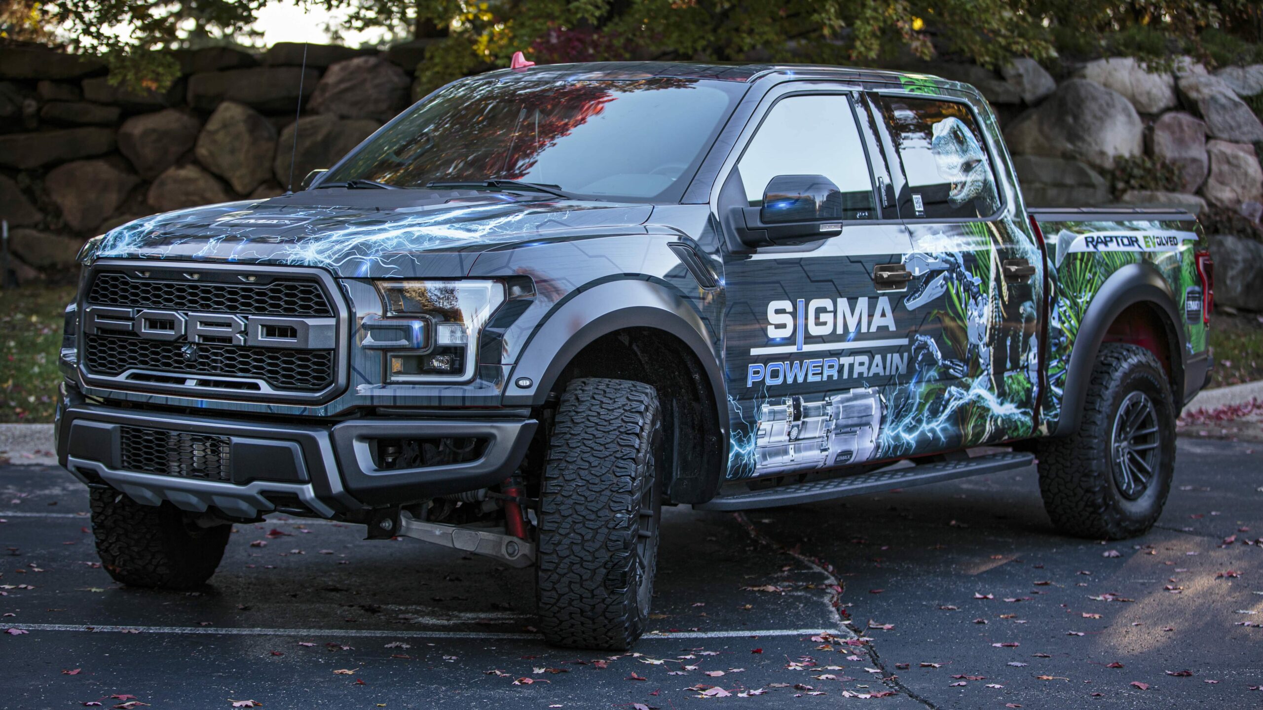
While the primary target market for the EMAX is Class 6-9 trucks (as well as targeting Class 1-6 vehicles with the smaller MID-Series counterpart product), SPT has developed its Raptor EVolved demonstrator EV – a Ford F-150 Raptor modified to run on an EMAX – to highlight the modularity and applicability of its flagship product.
“Putting a Class 9 gearbox in a Class 1 vehicle might seem insane, given that two EMAX gearboxes can move a 230 ton mining truck for 500,000 miles or more, and shift quality isn’t a major issue in really big, heavy vehicles,” Kimes notes. “But putting one in a 2.75 ton F-150 shows just how power-dense our gearbox solution is, and how free from NVH and other quality issues our shifting is.
“We retained the Raptor’s 2H, AWD, 4H, and 4L factory capabilities, and designed the extension housing on the EMAX to accept the production transfer case from the truck. The entire 800 hp powertrain occupied the space where the production 10-speed sat. We fit in the tunnel nicely and there were no interference issues between the front axle propshaft and the EMAX.”
The EMAX system in the Raptor uses a modified DS (Dual Stack) HVH 250 from Cascadia Motion. In this customised system, the motors together produce a continuous torque of up to 960 Nm, and can sustain a maximum power output of roughly 800 bhp.
“The EMAX can take input torques up to 4600 Nm, so these motors are undersized for the gearbox, but about the right size for an F-150,” Kimes notes.
He adds that the maximum output shaft torque in the Raptor EVolved demonstrator is 3009 Nm at A1B1, 2222 Nm at A1B2, 1305 Nm at A2B2, and 960 Nm at A3B2. Also, the Raptor’s transmission to the wheels multiplies this torque by 4.1, for a total traction torque output of 12,337 Nm.
MID-Series
While the EMAX has been designed principally for Class 6-9 truck EVs, SPT also manufactures the MID-Series powertrain, a smaller solution embodying largely identical power flows and electrically actuated clutch systems but aimed at last-mile delivery vehicles from Class 1 to 6.
The MID-Series uses OEM-validated Ravigneaux gearsets identical to those in the 6R100 Ford transmission used in the F-250 among other vehicles. “Those particular gearsets were ideal because we needed a capable four-node gearset with hard-finished gears, and which was readily available,” Kimes says.
“The MID-Series is an evolution of an older system called the SST [Sync Shift Transmission] that we made in 2011-12. We undertook a significant design change in 2019 to make it modular like the EMAX.
“The newest generation of electric clutches, sensors, controls and case changes were implemented predominantly for commonality of parts with the EMAX, and to allow the MID-Series to be used flexibly across either a central drive powertrain or an e-axle, with minimal changes between the two use-cases.”
Specifications
EMAX powertrain
18 in (45.7 cm) (not including user’s choice of e-motors)
All-electric
Planetary gear sets
Maximum input torque: 4600 Nm
Maximum output torque: 30,900 Nm
Minimum vehicle size: Class 1
Maximum vehicle size: Above Class 8
Motor A first gear ratio: 3.63:1
Motor A second gear ratio: 1.72:1
Motor A third gear ratio: 1:1
Motor B first gear ratio: 2.64:1
Motor B second gear ratio: 1:1
Some key suppliers
Microcontrollers: STMicroelectronics
Sensor chips: Allegro
Powertrain control modules: Powertrain Control Solutions
Motors: Cascadia Motion/BorgWarner
Motors: Dana TM4
Electromechanical actuators: McCleer Power
Electromechanical actuators: Applinetics
Bearings: Koyo
Inverters: Cascadia Motion/BorgWarner
ONLINE PARTNERS

