


Reducing models of EV behaviour
(Courtesy of Siemens)
The use of reduced order models (ROMs) can speed up the development of e-mobility platforms (writes Nick Flaherty).
The development of e-mobility platforms requires a complex interplay between different engineering teams for the mechanical, thermal, electrical, control and software design. ROMs from 3D design tools can be substituted for 1D system simulation models to provide more accurate and detailed results, so teams can make an informed and correct design choice earlier.
A ROM is a simplification of a high-fidelity static or dynamic model that preserves essential behaviour and dominant effects, for the purpose of reducing the solution time or the memory storage capacity required for the more complex model.
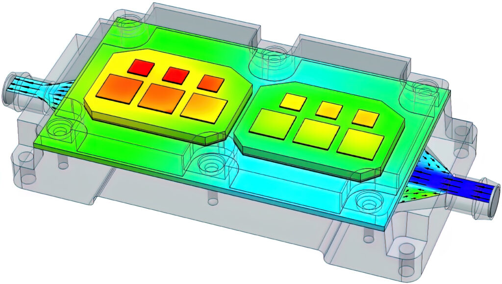
A BCI-ROM (boundary condition independent – reduced order model) workflow takes models from CFD tools such as Siemens’ Simcenter that are often used for developing liquid-cooling systems for high-power traction inverters that use a PCB with power semiconductor devices such as IGBTs or MOSFETs. The PCB is mounted on a coldplate with flow channels for the liquid to pass through for cooling, and the mass flow rate and the temperature of the liquid are controlled by a pump and a fan-cooled radiator.
High-level 1D simulation tools can be used to represent the rest of the EV apart from the PCB’s coldplate. The high-level model contains a longitudinal vehicle, VCU and driver models, which allow the specification of fundamental parameters such as the vehicle mass, which depends on the mass of a battery pack, rolling coefficients, aerodynamics, wheel dimensions, gear ratio and the driving cycle.
The power electronics that control a permanent magnet synchronous machine, a three-phase inverter high- and low-voltage batteries, sensors and controllers, can also be modelled at the 1D level, along with the cooling pump, radiator, fan, expansion tank and sensors that make up the cooling system.
Tools such as Simcenter FLOEFD support multi-physics simulations for a full 3D CFD simulation of the traction inverter to calculate the temperature distributions in it, as well as the flow pattern. However, owing to the complexity of the model and computational power requirements, it would not be feasible to solve 3D CFD and 1D system models simultaneously.
Extracting a ROM makes the overall model up to 40.000 times quicker to solve compared with traditional 3D CFD models. Such models are also BCI, which allows the engineer to vary the thermal environment of the model for example by changing the peripheral heat transfer coefficients (HTCs) without affecting the accuracy of the simulation. solution. BCI-ROMs can also be exported as a functional mock-up unit (FMU), making it portable and easy to embed into other tools.
Once the FMU of the inverter is imported into the high-level simulator, the calculations for the system can be solved. During the solution, the cooling system loop will provide transient HTC values and fluid temperatures to the FMU, while coldplate heat flux and component and cold plate temperatures will be sent back to the system. As the cooling system is a part of the whole EV, the simulation shows how the calculated inverter temperatures will affect the vehicle’s performance, such as range and coolant temperature.
Further work could include experimenting with different inverter designs, substituting IGBTs for MOSFETS, and so on, to see which components have a critical effect on the entire system.
1D system-level and 3D assembly-level designs often differ in terms of the purpose, power requirements and duration of the simulations. Expanding 1D systems with accurate but quick-to-solve 3D models enables engineering teams to produce more realistic simulations at earlier design stages, ultimately allowing you to reduce time to market.
ONLINE PARTNERS

