


Reduced rare earth and magnet-free motors
(Courtesy of Audi)
Attractive options
The race is on to find ways of reducing the industry’s reliance on EV motor magnets made from rare earths. Peter Donaldson looks at the latest advances
Rare earth (RE) magnets are essential components of the most efficient torque and power-dense motors used in EVs. However, factors including price, sustainability and geopolitical threats to supplies have pressured governments and industry into examining alternatives in terms of motor technology, systems engineering and the supply chain.
These pressures fluctuate, and the large increase in the price of the most critical heavy rare earth (HRE) materials, driven by Chinese export and price controls, occurred in 2011. “A year or so after that, the prices fell and stabilised, and machines using HRE magnets have since dominated the traction market,” says Dr Gabriel Domingues, senior staff engineer e-mobility, technology and portfolio management at at BorgWarner.
Nonetheless, this scare triggered a significant increase in r&d efforts to find alternatives for use in traction motors, principally non-RE magnets and motor topologies that don’t use permanent magnets (PMs) while preserving as much performance and efficiency as possible.
The compound most widely used in EV motors is neodymium iron boron (NdFeB), doped with dysprosium (Dy) to preserve the magnetic properties at high temperatures; NdFeB magnets have the highest maximum energy product (MEP). MEP is analogous to energy density, and is calculated as the maximum product of the material’s residual magnetic flux density (its degree of magnetisation) and its coercivity (its ability to resist demagnetisation).
Research organisation IdTechEx says that as, of 2020, around 77% of the propulsion motors in PHEVs and BEVs were PM machines, with the rest divided between the magnet-free induction machines (IMs) at 17% and externally excited synchronous machines (EESMs) accounting for just 6%. Percentages for each technology vary in subsequent studies, but not by much.
“Those numbers sound reasonable,” says Equipmake’s CEO Ian Foley. “Tesla got the bulk of the EV market early on, and they were initially all induction motors.
“I think RE magnet motors are going to prevail unless the sustainability argument changes things significantly, but normally the economic argument wins out. The [EESMs] being produced at the moment have got quite complex electronics though to make sure they are brushless, and that’s more expensive.”
Primary versus secondary drives
Dr Domingues emphasises the importance of distinguishing between primary and secondary drives in the use of non-PM machines in automotive applications. He defines a primary drive as the one that provides most of the propulsion effort, and the secondary drive as one that improves performance and enables all-wheel drive.
(Courtesy of Toyota)
“When PM machines are used as a primary drive they provide the highest cycle efficiency, which results in the use of the smallest battery for a given range for a given performance, while doing so in the smallest footprint,” he says.
However, as secondary drives they tend to consume more energy than IMs, even when they are not delivering power, unless there is a disconnect system. That’s because of the high zero-load losses and the need for field-weakening currents at higher speeds, he explains.
“With that in mind, and driven by the cost, environmental and supply chain challenges, secondary drives will probably continue moving away from PM and into non-PM topologies,” he says.
An example that would seem to bear this out is Tesla’s combination of a PM-assisted machine on the rear axle of its Model 3 Long Range Dual Motor and an IM at the front.
Dr Domingues argues however that the analysis is more challenging for primary drives, because there is a clear gap in the efficiency and performance between PM and non-PM topologies, which affects other key parameters such as the battery capacity required for a given range. He says these applications can tolerate slightly more uncertainty in the price and supply chain than secondary drives can, while still providing the best possible system, as long as steps are taken to reduce the price and supply chain risks.
“At current material prices, and assuming a reliable supply chain, it would be hard to motivate a significant reduction in market share of PM machines,” he says. “However, if magnet prices linked to HRE materials and/or concerns over supply uncertainty increase, it should be expected that more system-level compromises will be accepted to accommodate a larger share of non-HRE motors.”
Adopting alternatives
In its 2022-32 EV motor forecast, IdTechEx provided a number of examples of non-RE and non-PM motors being adopted by automotive majors for new cars. These include BMW’s RE-free fifth-generation EV powertrain, Audi’s use of IMs in the e-tron and Renault’s use of a magnet-free motor.
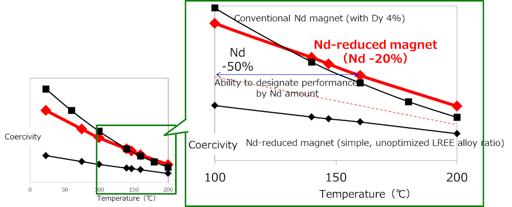
Also mentioned were Nissan’s 40% reduction in the amount of dysprosium in its motors announced in 2012, Honda’s 2016 statement that motors in its hybrids no longer contain any RE materials, and Toyota’s 2018 claim that it had developed the first neodymium-reduced, heat-resistant magnet.
Fundamentally, there will always be an energy efficiency penalty for the use of technologies that don’t use permanent magnets, because they have to draw current to create magnetic fields in their rotors, fields that are inherent in the magnets in PM machines.
There’s a similar penalty associated with the replacing RE materials with non-RE magnets in PM machines, which will have some combination of greater size and weight, and lower efficiency.
Overall approaches to the problem can be divided into three broad areas – fix the RE supply problems, accept the limitations of non-RE magnets and non-PM machines, or apply systems engineering and optimisation to squeeze as much efficiency out of these alternatives as is practical, for example through advanced motor control technologies.
However, this strong r&d focus on reducing the use of RE magnets is not driven by the pull of the current market, Dr Domingues argues. “These solutions do not dominate the current automotive market, nor do they currently produce the best overall system solution. Instead, these efforts are addressing potential needs and are meant to further solutions that could serve as a hedge.”
Fixing the supply chain
Solving the supply chain problem is the focus of work by, for example, the European Raw Materials Alliance (ERMA) and the UK Advanced Propulsion Centre (APC). Both recognise China’s continuing dominance, not so much in the mining of RE materials – which incidentally are not particularly rare – but of processing them into magnets. Taking sourcing and processing together, China controls 95% of the supply chain, according to Bhavik Shah at the APC.
Published in 2021, ERMA’s report, “Rare Earth Magnets and Motors: A European Call for Action”, set out to identify and address regulatory bottlenecks and to find other opportunities to support the growth of alternative European and global RE supply chains, and to increase their production, processing and recycling.
According to the report, 95% of EVs use traction motors with RE magnets, and the quantities required annually worldwide are expected to grow from 5000 tonnes in 2019 to as much as 70,000 t by 2030.
Europe imported about 98% of its RE permanent magnets from China, amounting to 16,000 t a year; while Europe has significant RE reserves of its own it was not mining them at the time of the report’s release. What’s more, less than 1% of RE magnet scrap was recovered in ‘urban mining’ operations annually, neglecting a large potential resource with a small carbon footprint.
The report identified 14 projects “from mine and urban mine to magnet” that would form the foundation of a European rare earths industry capable of supplying 20% of EU demand by 2030.
In the UK, the APC has developed a roadmap for establishing a robust magnet supply chain encompassing the raw materials, typically oxides of the RE metals, the intermediate alloying stage and their formation into the final magnets; Shah notes that the foundations of a supply chain independent of China are already in place. Australian mining company Lynas Rare Earths supplies the UK with the raw materials, which are alloyed by Less Common Metals in England before being sent to VAC Vacuumschmelze in Germany for turning into magnets.
(Courtesy of BMW)
Magnetic options
The APC has also compiled a roadmap for electric machine development that addresses alternatives and supplements for RE materials.
Five magnetic materials were ranked according to their likelihood of being adopted alongside sintered NdFeB magnets in EVs. Using a 0-10 scale, with 0 meaning not at all likely and 10 meaning extremely likely, polymer NdFeB and iron ferrite both scored above 7, with cerium and lanthanum scoring about 5, samarium cobalt around 4.5 and aluminium nickel cobalt about 3.
Lee Empringham, co-founder of power conversion specialist The Thinking Pod innovations and Professor of Power Conversion Technologies at the University of Nottingham, reports a move in industry towards the use of ferrite magnets.
“Ferrite-based magnets are not as strong as RE magnets, but you can still boost the performance of a reluctance motor, for example, to the point where you are getting a good power factor over a good range, so it’s a good compromise,” he says. “I think we’ll see more research into improving IM technologies and also PM-assisted synchronous reluctance motors.” (This kind of motor is often referred to as the PMASynRM.)
Although they have a lower MEP than RE magnets, ferrite magnets also have lower electrical conductivity. That is an advantage, because it significantly reduces eddy current losses and the associated heat output.
Ferrite magnets also have a higher Curie point than their RE counterparts, so they retain their magnetic properties to higher temperatures. That can improve reliability and bring system-level benefits through, for example, reduced demands on powertrain thermal management.
Using magnets with a lower MEP requires major changes in motor design to provide the required performance, Dr Domingues notes. “If we consider a conventional IPM design, an increase in the required amount of PM material is likely if the remanence of the magnet used is lower,” he says.
“Similarly, extra care should be taken regarding the risk of demagnetisation and the expected performance after demagnetisation. If the coercivity of the PM material is lower, this could drive an increase in PM material use and/or significant changes in the rotor geometry to mitigate demagnetisation.”
He adds that another way to use relatively low MEP magnets is to change the motor topology slightly to that of a PMASynRM. “Furthermore, the geometry can be optimised so that the magnets are buried deeper in the rotor, reducing the risk of demagnetisation.”
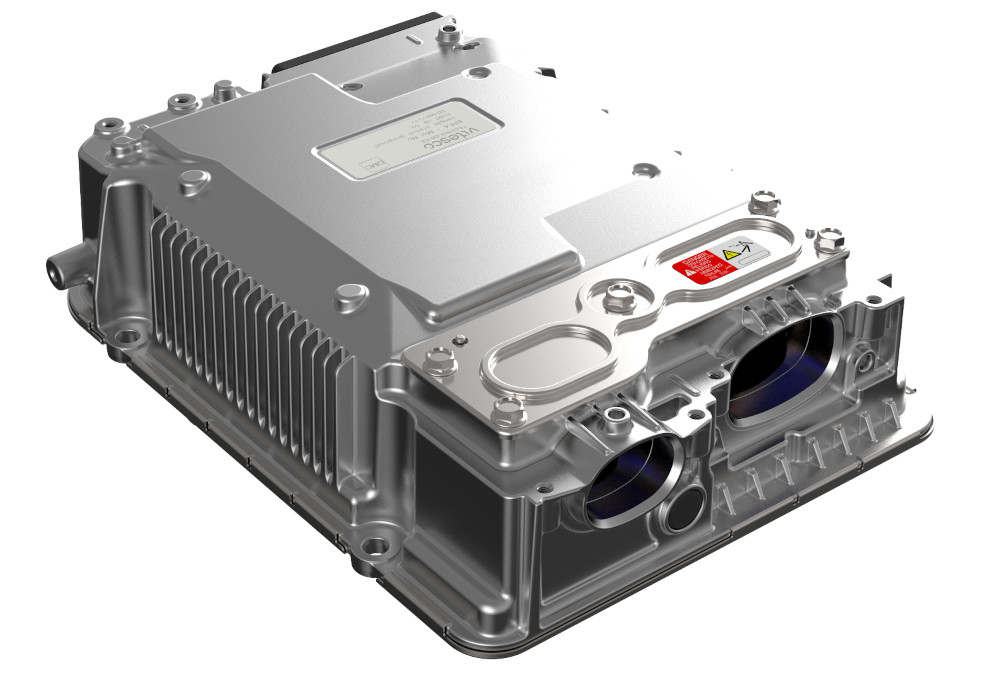
(Courtesy of Vitesco)
Induction machines
AC induction machines (ACIMs) have no permanent magnets. In an ACIM, the controller uses alternating current to create a rotating magnetic field in the stator that moves across the windings in the rotor thereby inducing a current in them.
This induced current in the rotor windings in turn creates a magnetic field that interacts with the stator field so that the rotor spins in the same direction as the stator field, only a little more slowly. The speed difference between the stator field and the rotor defines ACIMs as asynchronous machines, and is essential because it is their relative movement that induces the rotor currents.
ACIM efficiency has been improved through the use of copper conductors in the rotor, with Tesla the best-known exponent in the automotive industry, thanks to copper’s high conductivity. In practice, that means copper wires or hairpins can be smaller than aluminium for the same conductivity, although it is also far denser and more expensive, as well as harder to process and recycle.
ACIMs are a mature technology, which means that large improvements are unlikely to come easily. However, carefully rating them to suit the application and clever detail design that could emerge from the use of advanced simulation and manufacturing techniques are promising.
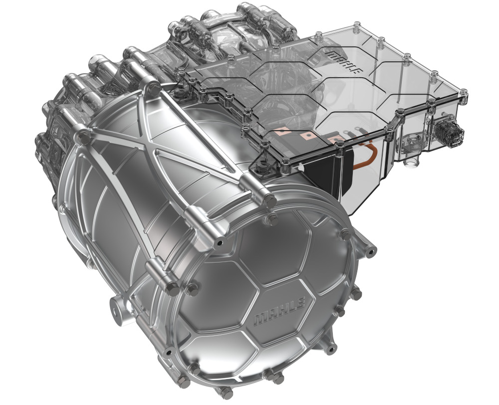
(Courtesy of Mahle)
Empringham points out that an IM can deliver much more power than its rating for a short period, but a PM machine cannot without overheating and damaging its magnets. “You might be able to drive a PM machine to 50% more than its rating for a short time, whereas you can get maybe a three fourfold increase in power over its rating from an IM for the same short period,” he says.
“You could get 100 kW out of a 25 kW IM for a short time without issue, but you wouldn’t get 100 kW out of a 25 kW PM machine.”
Dr Domingues remarks that there is little to be gained from trying to improve the peak efficiency of IM machines to compete with equivalent PM machines. “Instead, we need to try to lean into the inherent advantages of IMs, specifically their relatively high efficiency at high speeds to try to come up with systems and motor designs that succeed at converting most of the energy in favourable operating points.”
He adds that developments in conductors and thermal management could enable higher torque densities and efficiencies in IMs and other motor types.
“Several research labs and start-ups are working on conductors with a lower resistivity than that of copper,” he adds. “That will have a major impact on all motor types, as it will provide a path for reducing the copper losses, and through redesign potentially improve the core loss as well by reducing the required space claim for conductors and opening space for additional core material,” he explains.
“Another development path is towards advanced thermal management solutions that could enable an increase in the continuous performance of IMs.”
External excitement
Arguably the front runner among the magnet-free alternative motor technologies is the externally excited synchronous machine (EESM), sometimes referred to as the wound rotor synchronous machine (WRSM).
In an EESM, the controller provides a switched current to create a rotating magnetic field in the stator, while a separate DC feed provides current to the rotor through a slip ring to generate the magnetic field around its windings. The rotor spins at the same rate as the field in the stator, making the EESM a synchronous machine.
Renault Group, Valeo and Valeo Siemens eAutomotive are developing these cooperatively, for example, and Vitesco is working on its own machines.
Dr Domingues says EESMs represent a good compromise between PMs and IMs in terms of energy consumption and size, while only requiring relatively abundant and easily sourced materials. However, the rotor excitation system used in place of the magnets needs additional power electronics and produces its own losses, he adds.
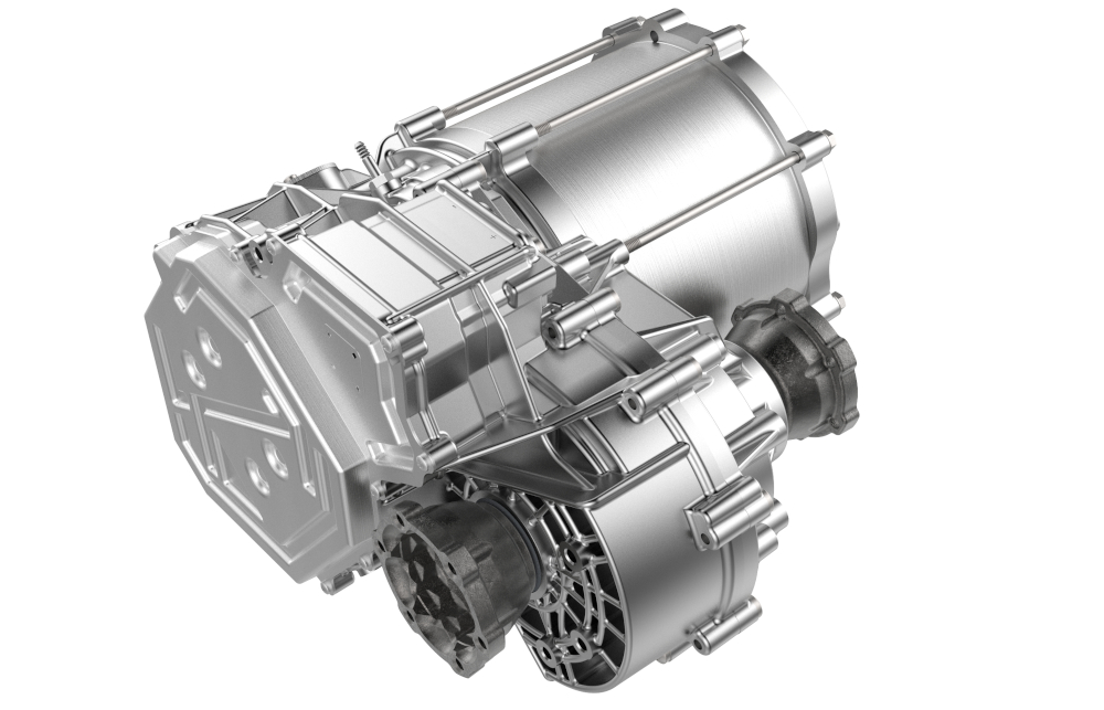
Furthermore, the slip ring is a mechanical contact that is a source of friction losses and is subject to wear. Dr Domingues notes that BorgWarner is working on an integrated wireless inductive power transfer system that solves these problems.
Mahle is reportedly developing a comparable system that uses an AC-fed induction coil to energise a receiving coil in the rotor, eliminating the need for a slip ring. The company claims an efficiency of more than 95% at all operating points.
Another advantage of the EESM (and one that it shares with the IM) is that the rotor current can be changed, adding an extra degree of control that can be used to optimise energy consumption, also allowing the rotor to be completely demagnetised when the motor is not needed for propulsion, greatly reducing no-load losses. “However, doing so could have an impact on the dynamic response, as there will be a delay owing to the need to re-magnetise the rotor,” Dr Domingues says.
Empringham likens the EESM to a machine with (imagined) controllable permanent magnets. “You can get a motor with a very broad operating range quite readily,” he says. “You can weaken the field to go to higher speeds, and you can increase the field strength to get more torque at lower speeds. They are very flexible from that point of view.”
He adds that it is possible to achieve similar functionality with a well-controlled IM, but with lower efficiency at low powers.
Foley concurs, focusing on a peculiarity of typical automotive applications that could provide an opportunity to optimise an EESM. “Automotive has got this unusual requirement for transient high power but very low continuous power,” he says.
He notes that motor manufacturers produce efficiency maps, and like to quote a data point for peak efficiency that is only relevant if the motor spends most of its time at that point. “There might be a sweet spot where you can optimise for very low power,” he says. “There might be an efficiency benefit there.”
Although the EESM offers better efficiency over a broader range than the IM, it is also more complex and costly, he adds.

Spinning with reluctance
Reluctance opposes magnetic flux, just as resistance opposes electric current. Reluctance machines (RMs) that exploit this effect have stator windings, but the rotor features neither permanent magnets nor windings, and needs no electrical connections.
The fields created by the stator windings induce non-permanent magnetic poles in the laminated silicon steel from which the rotor is typically made. These fields interact with the magnetic fields in the stator to minimise the reluctance, the rotor poles aligning naturally with the stator poles.
The basic division among reluctance machines, is between synchronous (SynRM) and switched (SRM) types. In the former, the rotor turns at the same speed as the rotating magnetic field in the stator, although with a positional lag due to load. In the latter, the rotor is turned by sequentially energising groups of poles in the stator. The most promising for EV use are the SRM and the permanent magnet assisted SynRM (PMASynRM).
SRMs have potentially very high torque density, mechanical simplicity, low-cost sourcing and manufacture, reliability, longevity and tolerance of high operating temperatures. They also offer better coasting performance than PM machines thanks to the absence of magnetic drag, and safer failure modes because they don’t generate excessive voltages.
“The issue is always that the motor control is very complicated, and the motors are noisy,” comments John Fiorenza, president of motor manufacturer Motenergy. “It has been that way for 30 years.”
Empringham explains that to get the best out of SRMs and overcome the disadvantages, a very high bandwidth power electronic controller is essential, meaning it must be able to supply power over a very wide range of frequencies, plus accurate rotor position feedback.

“Standard IMs, SRMs and so no require a relatively pure sinusoid waveform to drive them, but SRMs need a really complicated one to do that properly,” he says. “If you drive them with a simple square wave they will spin, but you won’t get the performance benefits that you would if you had a high-bandwidth power converter and an effective control algorithm.”
Because SRMs are controlled by switching groups of coils on and off, the torque tends to ripple. “You need to be a little more innovative in how you do that in order to get a smooth torque output,” Empringham says. “For example, you would energise a coil and it would attract the rotor, but the attraction force depends on the position, so you would have to modulate the current according to the position in order to smooth that torque out, which is very challenging.”
The PMASynRM, as the awkward moniker suggests, is a hybrid that adds permanent magnets to the rotor of a synchronous reluctance machine, and is the type of motor Tesla uses at the back of the Model 3 Long Range. Adding permanent magnets to the rotor increases the motor’s power factor and reduces the dominant ohmic losses in the stator, and ferrite magnets are sufficient for this task.
(Courtesy of Vitesco)
Different strokes
Motors of different topologies also affect how efficiently they use their magnetic materials. For example, BorgWarner generally uses radial flux machines with the rare earth (Nd) magnets positioned deep in the rotor in an IPM configuration, which has similar benefits to the PMASynRM technology. “That allows us to take advantage of permanent magnet and reluctance torque, which helps to reduce the quantity of magnet material needed,” Dr Domingues says.
“Furthermore, these machines can be designed to operate at high speeds, with some already in the market running at more than 24,000 rpm, and even higher speed designs are being evaluated. That reduces the required output torque of the machine and, consequently, it’s overall size and magnet content.
“Conventional axial flux machines tend to have the magnets on the surface of the rotor, and thus present relatively low saliency [the ratio of direct and quadrature inductance], which limits their ability to produce reluctance torque,” he says.
“Also, their operating speed tends to be limited owing to their comparatively large rotor diameters, so they require higher output torque for an equivalent application. Although axial flux machines tend to have a superior torque density and very competitive efficiency, they also tend to use a larger amount of PM material for these reasons.”
Equipmake develops high-performance motors, including PM types in which the magnets are arranged like the spokes of a wheel rather than a vee arrangement. “Spoke motors make better use of magnetic flux, but compared to a conventional vee-shaped IPM motor, you get less reluctance torque,” Foley says.
“So if you want something that’s very torque-dense, and not very power-dense, like our bus motor, you end up with a conventional IPM motor. The spoke motor is better if you want a combination of high torque density and high power density.
“From our analysis of the spoke motor, I think we can get performances that are very similar to what we believe the best-in-class axial flux motor can do, and I think we can do it with less magnet mass.”
A systems approach
The ability to make the most of reduced RE and magnet-free motor technologies depends to a large extent on sophisticated control of mechanically simple but electromagnetically complex machines, and on systems engineering more broadly.
“A systems-based approach to looking at the motor and the power converters together will be more important in future,” Empringham says. Ideally, he adds, motor, power converter and battery designers will come together to work out the best way to drive a good motor. “The way it seems to be going is towards more integrated motors and drives, so there is a higher chance that they will be designed as one system,” he concludes.
ONLINE PARTNERS
