


Production tests
(Image: Pickering Interfaces)
Electrified with confidence
Nick Flaherty examines how reliable, functional testing is crucial for manufacturers aiming to stay ahead in the rapidly evolving EV market
The latest report from the International Energy Agency forecasts that electric car sales will exceed 20 million units in 2025, representing over 25% of global car sales. The report also states that by 2030, EVs are expected to account for more than 40% of all car sales globally. To meet this demand, automakers and EV supply equipment (EVSE) manufacturers are accelerating development and deployment, but they face significant challenges in production testing.
Electrification is reshaping the automotive landscape, and manufacturers need more than just tools, they need confidence. With functional testing, a unified ecosystem bridges R&D and manufacturing so that manufacturers can reduce risk and stay ahead of evolving standards in a rapidly accelerating market.
Fragmented system architectures across platforms increase design complexity and time-to-market, while a lack of standardisation in power conversion and charging interfaces leads to compatibility issues and higher integration costs. There is also uncertainty around future charging trends that makes long-term investment protection difficult, and the high capital expenditure required for testing strains budgets and slows innovation.
Aligning early design validation with production testing ensures a consistent ecosystem of tools and workflows.
A standardised, unified solution can streamline fragmented system architectures and simplify integration across power conversion systems, including DC–DC converters, onboard chargers (OBCs), and EVSE. Scalable, future-proof test systems enable manufacturers to innovate confidently across electrification domains. For end users, this translates into faster access to reliable, energy-efficient EV systems that deliver consistent performance and compatibility across vehicle platforms and charging environments.
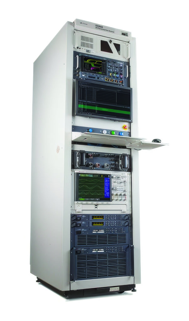
An EV manufacturing functional test platform can adapt to the diverse and evolving needs of EV manufacturers. Whether testing a DC–DC converter, OBC or both, the platform offers customisable configurations to meet specific functional test requirements. With built-in flexibility and comprehensive toolsets, the test system enables manufacturers to validate performance, ensure compliance and streamline production within a single, scalable system.
The platform comes with a large pool of options, such as a regenerative DC power supply, oscilloscope, power analysers and data acquisition system, ensuring that all testing capabilities are met.
The system is scalable to provide up to 120 kW while maintaining a compact footprint, seamlessly integrated within a single rack. Moreover, dealing with high-voltage safety is always the top priority. The test system includes several safety mechanisms to protect the user and equipment such as high-power output inhibit, emergency power off and user configurable touch-safe, high-power connectors. Development time is reduced with EV application specifications test case libraries for applications such as DC–DC converters, OBCs, and DC–DC and OBC 2-in-1 testing.
A different version is engineered to streamline EVSE testing with a unified platform that supports both AC and DC charging standards, eliminating the need for separate systems and reducing operational complexity. A modular charging interface allows for rapid swap-outs, enabling quick turnaround and minimising production downtime. The dynamic power sharing for an EVSE simulation with two charging leads, enables realistic emulation of peak load conditions, which is critical for validating performance and optimising energy distribution on charging systems.
(Image: Keysight Technologies)
Faster battery test
Researchers have developed a one-second EV battery health test that could transform reuse, cut waste and expand access to clean energy.
By 2035, around 150,000 tonnes of EV batteries in the UK are expected to reach the end of their life each year. At today’s market prices, those packs contain hundreds of millions of dollars’ worth of lithium, nickel and cobalt. Without effective reuse or recycling, this rising wave of waste risks locking away critical resources, while discarded packs can leak toxic materials, catch fire in landfills and create costly clean-up challenges.
One of the biggest barriers to reusing EV batteries is knowing, quickly and accurately, which ones are still good enough to use. The breakthrough test means that the health of an entire battery module can be checked in seconds, making large-scale reuse viable and helping batteries to last longer, perform better and create less waste.
Most discarded batteries still retain about 80% of their initial capacity, which makes them suitable for less-demanding uses such as energy storage. Until now, however, the process of testing used batteries to see whether they are safe and fit for reuse has been slow and expensive.
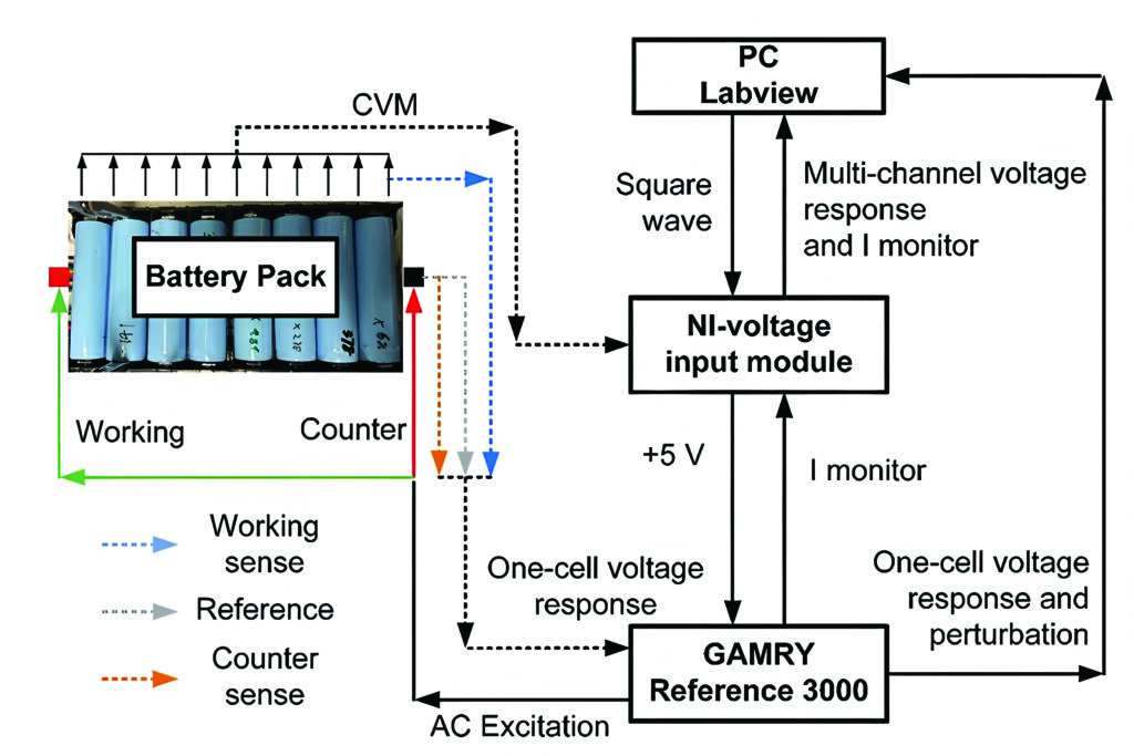
Researchers have developed a diagnostic method that can check the health of a battery module in about one second. Conventional methods can take minutes to hours per cell, meaning a single module might require days of testing. The new technique, called multi-channel, multi-frequency electrical excitation response (MMER), is hundreds of times faster, non-invasive and scalable to the pack level. It can even perform health checks in real time while batteries are being charged or discharged.
The technique is based on similar diagnostics used for hydrogen fuel cells, but lithium-ion batteries present some particular challenges in their complex operation that make them more difficult to diagnose using traditional electrical techniques.
The very fast nature of the MMER diagnostic technique allows developers to study the batteries while they are actually operating, charging and discharging, which has not been possible before. This could unlock advanced ‘live’ understanding that could be used in the onboard control systems of EVs.
The technique is rapid and highly scalable, meaning that it will help improve understanding of batteries across all three stages of their lifetime: after manufacturing for quality assurance, during operation in the vehicle and at pack end-of-life to inform recycling options.
The team tested used batteries from an end-of-life Tesla Model S using the MMER approach.
(Image: University of Oxford)
Test sensors
Thermal propagation and other EV battery faults begin when small problems in a battery cell such as physical damage, issues with charging/discharging, extreme temperatures and internal shorts are intensified by the constant flow of current through the cell. Many of these problems originate after the battery is installed, which is why monitoring in the factory is important.
Identifying faults that could lead to thermal events is important for safety. For economic and environmental reasons, it is also necessary to ensure that the battery elements being installed in an EV are healthy enough to forecast a long life for the system and the vehicle.
Ideally, a well-designed and well-manufactured battery will store energy and only discharge that energy to power the vehicle. Of course, small imperfections are inevitable, and all batteries will experience some form of leakage current. Small ‘microshorts’ within a battery cell will cause internal currents that slowly deplete the stored charge in a cell. The amount of current leakage a battery cell experiences correlates with a shorter battery lifespan.
Currently, the process that manufacturers typically follow begins with fully charging the battery cell, then leaving it in a temperature-controlled environment and tracking how the voltage drops over time. Any reduction beyond a prescribed threshold would indicate a leakage current that would make the cell inappropriate for installation in an EV.
Even in cases where significant leakage current is an issue, the resulting voltage drop is very slow. Depending on the size of the battery, this process can take up to one month to reveal a leakage current problem.
Graphene transistors can be used in battery packs to monitor the current for faster production testing.
The two-dimensional nature of the graphene sensing element produces a cleaner, more precise reading of the magnetic fields produced by the charging current. The sensors can track current levels as low as tens of microamps with suitable field concentration. This allows the sensors to be employed in a new testing process, which substantially reduces the time it takes to measure leakage current, thereby expediting the process of getting quality battery cells out the door.
To initiate the leakage test, the battery is quickly charged at a high fixed current until it reaches its nominal ‘charged voltage’ (i.e., somewhat short of a full charge but where internal microshorts will be activated). Enough current is applied to maintain this fixed voltage and the current level is measured as the battery reaches full charge. At full charge, the current level should diminish to zero; however, internal leakage will prevent that from happening. Tracking the reduction in the current level provides accurate accounting of the leakage current.
Systems are currently being developed with manufacturers for EV test using this technique.
(Image: Paragraf)
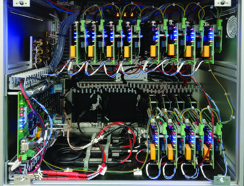
BMS test
A BMS is a core element within a battery pack, as used in an EV, hybrid or plug-in derivative with a number of roles. These include providing state-of-charge (SoC) and state-of-health (SoH) data to the vehicle’s ECU and other systems. Its main management roles are to optimise battery performance and provide protection in the event of cells failing.
Functional verification is essential for any BMS because it must meet the safety requirements stipulated in industry standards such as ISO 26262.
Also, as an EV’s battery pack is effectively its defining component, determining the vehicle’s maximum range and acceleration, for example, it must be reliable and have a life that is as long as possible. From a cost perspective, the battery pack equates to about one third of the price of the entire vehicle, so manufacturing and test costs need to be tightly controlled.
The controller unit is responsible for monitoring overall power levels. It protects against overcurrent to and from the battery pack, and accepts temperature readings/data from all responder units as well as controlling safety/contactor switches with all responder units, in case any need to be isolated in the event of overtemperature.
This links to a responder unit that is responsible for temperature monitoring and cell balancing, which ensures that cells connected in series receive the same charge. The most common method of cell balancing is passive (or charge shunting), in which cells that have received their full charge are protected from receiving further charge. Essentially, a resistance is placed in parallel with the cell that needs protecting. Most of the current will then bypass that cell to reach and charge others in the series stack.
Verifying that a BMS from a production line will function correctly starts by determining the functionality of the responder units within the modules. This requires data from cells being charged, discharged and failing. While good (functionally verified) responder units are used to verify control units, a simulation of the battery is needed to provide the data for testing.
All of this needs to be delivered as fast as possible on the production line, in a matter of seconds.
Core to the test system is the ability to simulate multiple cells at once but for the test stations to be as compact as possible. Also, test accuracy and speed need to be high and, in this respect, a test time of 15 s per BMS (off the production line) was set as a benchmark.
A test system based on the PXI standard provides modularity and the performance needed to meet the test time.
The simulator is effectively a power supply module with six isolated outputs, each capable of supplying up to 7 V DC at up to 300 mA. Each channel can also sink current and therefore behave as a load, just as a battery cell does when being charged.
Also, each channel is fully isolated from ground and from adjacent channels, allowing them to be connected in series to simulate cells in a stacked architecture. A 750 V isolation barrier allows the module to be used as a lower-power version of a battery stack, representative of those used for vehicle propulsion.
Each channel provides independent power and sense connections, allowing the battery simulator to sense a remote load and correct for wiring losses. The battery simulator is designed to respond to dynamic loads, minimising the need for local decoupling capacitors at the load.
A control line on the user connector allows the user to shut down all battery simulator channels with one signal. Multiple control lines can be linked together to provide an easy way of inhibiting the output when using several series-connected modules. This also provides a means of automatic shutdown when connectors are removed.
Front-end fixtures can be configured for verifying either BMS controller units (up to four at a time) or responder units (up to 10 at a time).
All tests were written in ATEasy software as a test sequencer. The software and drivers are capable of multithreading, and it is possible to drive four battery simulator modules to allow simulation of 24 cells at once.
For the responder cell measurements, all the simulators are set with different voltages. These are read by the BMS responder and communicated via UART to the BMS controller.
A PC connected via CAN bus then compares the recorded voltages against reference ones. It is a relatively simple Pass/Fail test, but it verifies that everything between the cell and the BMS responder’s CAN bus interface is functioning correctly.
For cell balancing, the simulator cards’ channel outputs are again set with different voltages. Then, a command from a BMS controller is sent to the responder units to commence cell balancing. The balancing current is read by the test station.
To measure the cell temperature, each power module contains a number of thermistors. The responder unit’s ability to read these (under ambient/room temperature conditions) is verified.
Multithreading allows four cards to be driven at once, which maps well in instances where a single instrument is going to perform the same test on multiple devices under test. In this case, the test software can interact with 120 simulated cells in just a few milliseconds, whereas single-threaded tests and the use of a slower bus (LXI or GPIB, for example) would take tens of seconds.
To functionally verify a full BMS with the controller unit and all its responder units takes around 60 s. Four test stations allow testing of the BMS systems as they come off the production line at a rate of four per minute.
(Image: Pickering Interfaces)
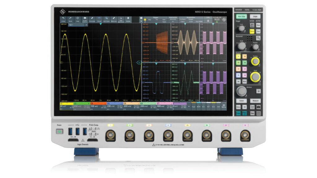
Traction inverter test
The traction inverter is a vital element in the electric drivetrain that takes the DC electrical power from the battery pack and delivers AC power to the motor. It is responsible for accurately, safely and efficiently controlling the motor, thereby improving driving range, responsiveness, smoothness, traction and handling.
Traction inverter designers face numerous challenges, such as minimising switching losses, maximising thermal efficiency and ensuring EMI compliance when using wide-bandgap, high-voltage semiconductors. These challenges can be addressed with a robust testing approach.
The traction inverter consists of three fundamental components: the DC–DC boost converter, DC–Link capacitor and DC–AC inverter.
Each component and the overall module face a range of design challenges, including minimising switching losses and maximising thermal efficiency and verifying stability under different loads and environmental conditions. This ensures maximum efficiency at high switching frequencies and multiple output voltages to ensure correct switch timings to verify control algorithms.
A fast-sampling multichannel oscilloscope provides a range of test applications from RF switching analysis and power efficiency optimisation to gate driver characterisation and power integrity. This can trigger and decode CAN, LIN and Ethernet protocols, enabling capture and identification of digital errors as well as delivering high-precision impedance analysis for measuring equivalent series conductance to the level of nanohenries and equivalent series resistance to the level of micro-ohms over a wide frequency range with excellent repeatability. A double-pulse tester system can characterise high-voltage silicon, silicon carbide and gallium nitride semiconductors with an isolated probing system with a high common-mode rejection ratio.
(Image: Rohde & Schwarz)
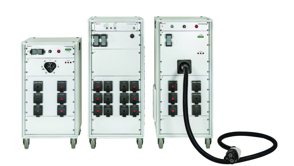
Megawatt charging test
As the electrification of heavy-duty transport accelerates, the demand on charging infrastructure is increasing exponentially. While the Combined Charging System (CCS) supports charging power up to 500 kW, this is insufficient for heavy-duty vehicles with battery capacities ranging from 500 to 1000 kWh. This is where the Megawatt Charging System (MCS) comes into play for charging power of up to
3.75 MW (3000 A at 1250 V DC). This uses Automotive Ethernet (IEEE 10Base-T1S), replacing the Powerline Communication (PLC) protocol used with CCS and a liquid-cooled connector with automated locking and optional robotic support.
These specifications make it possible to charge a 1000 kWh battery in under 30 minutes, an essential factor for economic operation of electric trucks in long-haul transport or other heavy-duty vehicles, such as mining vehicles and construction and agricultural machinery.
Implementation of an MCS introduces a range of complex technical challenges that go far beyond current e-mobility standards. One of the most critical hurdles is thermal management. At current levels of up to 3000 A, significant heat losses occur, which not only reduce efficiency but also pose safety risks. To reliably dissipate this heat, the MCS relies on an actively cooled cable and a connector system with liquid cooling, ensuring stable thermal performance even under continuous load.
Another key aspect is electrical safety. With charging voltages reaching up to 1250 V, the requirements for insulation, overvoltage protection and arc detection increase significantly. The MCS specification, therefore, includes multilayered safety mechanisms at both the hardware and the protocol levels. These include galvanic isolation, automated locking systems and continuous monitoring of electrical parameters throughout the charging process.
Implementing an MCS places significant demands not only on vehicle technology but also on charging infrastructure and energy supply. Typically, owing to the extremely high power levels – up to 3.75 MW per charging point – direct connection to the medium-voltage grid is essential. This means that MCS stations cannot be operated via conventional low-voltage connections like standard fast chargers. Instead, they require dedicated transformers and switchgear to deliver the necessary power.
A central issue in this context is load management. To avoid grid overloads while maintaining economic viability, MCS sites must be equipped with intelligent energy management systems. These systems coordinate charging schedules, prioritise vehicles based on operational need, and can integrate local energy sources such as photovoltaic systems or stationary battery storage. Especially in logistics hubs or highway corridors where multiple vehicles may charge simultaneously, dynamic load balancing is critical.
Scalability is another key consideration. The infrastructure must be designed to grow with increasing demand, both in terms of physical layout and grid capacity. This requires close collaboration between charging infrastructure providers, utility companies and local authorities, particularly when it comes to permitting and expanding medium-voltage connections.
Standardisation also plays a decisive role. Only if MCS charging points are interoperable across manufacturers and can be seamlessly integrated into existing backend systems will a widespread rollout be successful. The CharIN initiative is therefore working on the global harmonisation of MCS specifications to ensure interoperability. Testing to these standards is vital.
By aligning with standards such as ISO 15118-20 and actively contributing to the development of the MCS specification, test equipment makers ensure that MCS systems meet both current and future requirements.
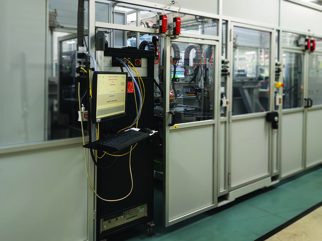
The latest MCS modular megawatt charging test system supports both EV and EVSE interfaces up to 1500 V and 1500 A, enabling conformance, interoperability and safety testing.
Built around a flexible core architecture, the system can emulate both EV and EVSE roles within a single solution. For EV testing, it acts as a fully configurable megawatt-class charging station, enabling validation of vehicle charging behaviour, safety mechanisms and charging communication under high-power loads.
For EVSE testing, the system emulates a next-generation EV to verify charging-station performance, interoperability, and compliance in a controlled and repeatable way. This dual-use capability reduces test complexity while accelerating development cycles.
The modular design enables realistic configurations for different test objectives. When combined with a Charging Cable Unit that features a liquid-cooled MCS charging cable, an Inlet Unit provides a vehicle-side MCS interface for realistic and repeatable EVSE testing, including controlled high-current operation with bidirectional power sources.
(Image: Keysight Technologies)
Acknowledgements
The author would like to thank the following for their help with this article: Elif Liebert at Keysight Technologies and Manuel Dos Santos at MSL.
Some suppliers of production test systems
Averna
AVL
BOLAB Systems
Keysight Technologies
MSL (All Circuits)
National Instruments
Paragraf
Rohde & Schwarz
Sciemetric
Tektronix
Click here to read the latest issue of E-Mobility Engineering.
ONLINE PARTNERS

