


Thermal Management 2018
levels of heat transfer from onboard semiconductors
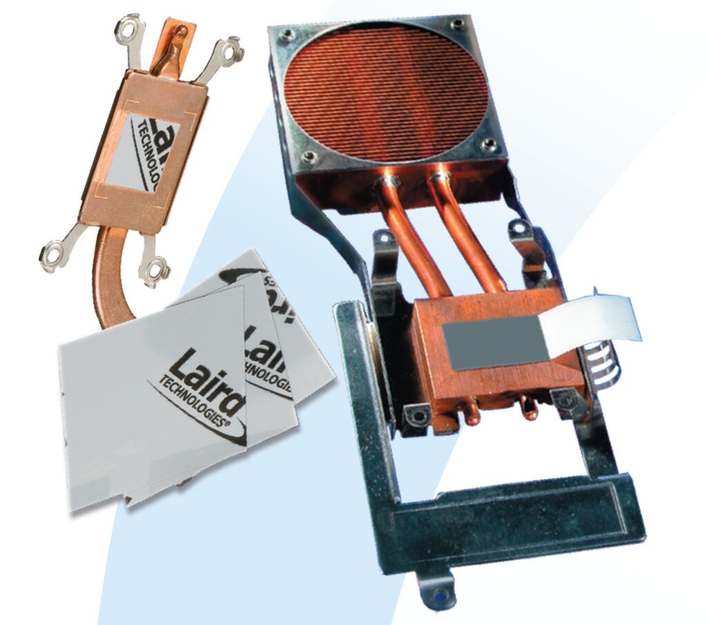
(Courtesy of Ventec Europe)
Heat treatment
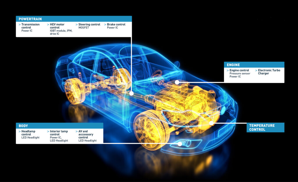
Nick Flaherty explains the issues surrounding the design and manufacture of temperature control systems for electric powertrains.
Thermal management is a key part of the design and construction of an electric platform, whether it be ground-based or airborne. The thermal performance of the electronic control system, battery management system and battery packs determines its performance as well as its reliability.
Effective thermal management can allow electronic devices to operate at higher temperatures and so run at higher frequencies, delivering higher efficiency and giving longer battery life and range. Maintaining a constant thermal environment also assists reliability, as operating above the qualification temperature shortens the mean time to failure (MTTF) of components and reduces the reliability of the overall system.
This MTTF is determined by the Arrhenius equation, a formula that correlates temperature to the MTTF. It allows designers to estimate the temperature-related impact given the qualification temperature of the devices and the application temperature as determined by the thermal management design – one that combines passive but complex substrates, heat sinks and heat pipes with active cooling systems driven by pumps.
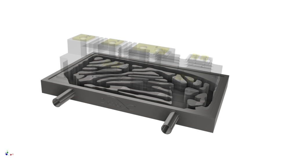
(Courtesy of Diabatix)
Effective thermal design is needed to offset any effects of poor thermal management, which can be severe. Many fast-charging algorithms for battery packs are based on the temperature of the cells, and exceeding the thermal capacity of the pack during charging or in operation can cause a fire. That means having an effective thermal management design to keep the temperature of the system within safe limits.
There are a number of design tools for doing this, most of which are based on computational fluid dynamics (CFD). Many of them are well-established for many different types of fluid flows, and some have been optimised for heat transfer, breaking the problem down into small elements and using finite element analysis algorithms.
This is computationally intensive, as more accurate analysis requires smaller and smaller elements and more processing power. The higher levels of processing power now available on desktops and in the cloud are giving designers more options for improving the thermal management of electrical systems.
Design tools are also taking advantage of the latest supercomputer clusters to gain more accurate results but also now include machine learning to further optimise the thermal design of components and subsystems.
System efficiency
Electric powertrains are far more efficient than petrol or diesel engines, so thermal management of the powertrain has traditionally been considered to be less of an issue.
For example, a typical family saloon car with a 100 kW rated diesel or petrol engine will need to deal with a heat load of around 80 kW being rejected to coolant, and more than 100 kW through the exhaust. An equivalent electric vehicle may need to deal with less than 15 kW of heat under peak conditions, implying that a simpler cooling system can be used.
However the peak energy, or heat flux, from semiconductor devices such as the IGBTs used in the traction drive is significant – as much as 400 W/cm2, the same as the surface of the Sun. Managing this high level of heat transfer is a major challenge.
The heat generated in the battery pack is a function of current and the internal resistance of the battery cells and interconnections, during vehicle acceleration, deceleration and charging, especially with the fast charging of large battery packs demanded by modern designs.
The flow of current in the battery packs that causes heating in the cells and the interconnections is proportional to the square of the current flowing multiplied by the internal resistance of the cells and the interconnect systems.
The higher the current flow, the greater the heating effect, and the batteries have to operate in a relatively tight thermal envelope. The cells can be damaged if fast charging is applied when the battery is cold, so sometimes heaters are needed, adding design complexity and increasing the power consumption.
Most lithium battery cells cannot be fast charged when they are at less than 5 C, and struggle to charge when they are below 0 C. They also begin to degrade quickly when the ambient temperature is above 45 C.
As fast charging rates are demanded to charge 200 kW battery packs in less than 30 minutes in higher performance electric vehicles, additional thermal management methods for the battery pack are now needed.
There are three common battery thermal management methods used these days – convection to air, either passively or forced; cooling by flooding the battery with a dielectric oil that is then pumped out to a heat exchanger system; or cooling via the circulation of a water-based coolant through cooling passages within the battery structure.
The choice of cooling method is critical to supporting the performance of the cells over their lifetime. In particular, the direction of cooling has been found to be critical in order to maintain good internal temperature gradients across the layers inside each battery cell. Airflow with the direction of travel of course is more effective than a transverse flow with a lower flow rate.
Unlike airborne systems, air cooling is unsuitable for most new high-performance electric vehicle applications, owing to the power density required and the inability to cope with a wide range of ambient temperatures. Thermal management designers say it is simply not possible to remove sufficient heat from within the battery with an air-cooling system alone, although some air cooling will generally occur if a battery is positioned on the underside of the vehicle as a result of the airflow created during driving.
Instead, tab cooling – which comes from connecting the tabs of the battery cells to external thermal systems – can help manage the internal temperature of the battery pack. Adding an internal heat pipe system built from metallic discs inside the cell and then linked to external heat sinks provides a thermal performance comparable to other cooling approaches, but gives more control over cooling as it prevents a temperature gradient developing between the layers of the cell.
This shows that cooling needs to be carefully targeted in order to prevent damage and preserve lifecycle performance, which design tools are increasingly coming to terms with.
Typically, a flooded dielectric cooling system will extract heat from the surfaces of the cells. This uses a waterbased coolant or an organic refrigerant circulated by a high-efficiency pump through a cold plate system built into the battery pack. The coolant can be used to remove heat from the pack and provide heating of the pack for fast charging at low temperatures.
The Tesla models S battery cooling system for example consists of a patented serpentine cooling pipe that winds through the battery pack and carries a flow of water/glycol coolant; thermal contact with the cells is through their sides by thermal transfer material. Again, this will remove heat from the side of the cells rather than from the tabs, and means that hard driving can lead to the battery packs overheating.
Pumps and cooling
Designing the cooling system to be as efficient as possible has a number of challenges. The system can vary from removing heat from leads to complex designs for cold plates with liquid cooling.
That in turn can lead to a coolant system that is hard to fill correctly, and means that a relatively much more powerful pump is needed when compared to the heat rejection in the context of a combustion engine. More pump power leads to the possibility of higher parasitic loses on the system, making it important to ensure that the design is highly optimised.
To minimise thermal stress in the system and reduce parasitic power consumption, the coolant pump and fan speed should be controlled at a system or vehicle level. The system control algorithm should have multivariable control to account for the interdependency between the coolant flow delivered by the pump and the flow of cooling air from the electric fans.
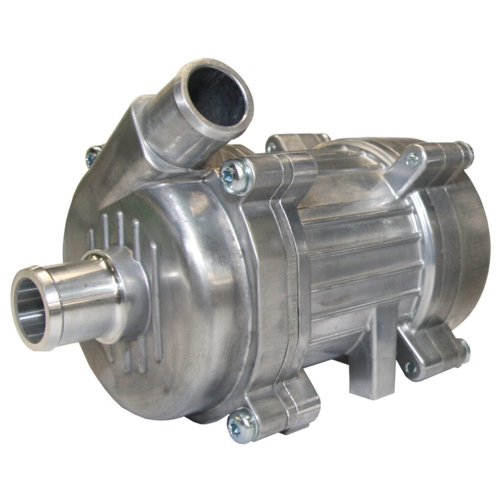
(Courtesy of Avid Technology)
It should also maintain a steady operating temperature for the motor and electronics modules, with the key control variables being device and coolant temperatures. There may be additional cooling requirements from items such as braking resistors, transmission oil coolers and other devices on the vehicle to be considered as well.
Effective cold plate design typically leads to a higher pressure drop across the battery pack owing to the long and narrow coolant channels required. The pressure drop then needs an electric coolant pump that can generate high flow rates and static pressures.
Once the coolant has passed through the battery pack it is then circulated through a heat exchanger, where heat is transferred to ambient airflow generated by a fan. This is important if the vehicle is to be used globally, where ambient temperatures could come close to the maximum acceptable temperature for the battery, but fans are less reliable than liquid-cooling systems.
This kind of two-phase cooling is needed to allow the battery to be kept at an optimum temperature that is below ambient. This reduces the overall power consumption of the system but adds more components, design complexity and cost.
The relatively small temperature gradients between the battery system and external air can mean that heat exchangers are needed, even though the amount of heat being rejected from an EV is around 90% lower than a comparable internal combustion vehicle drivetrain. That means the battery cooling system’s power consumption can be one of the largest parasitic power draws in the EV drivetrain and is closely linked to the vehicle’s performance.
Because of this high potential parasitic power consumption it is a false economy to select cheap but inefficient fans and pumps for the battery cooling system. The overall power consumption of the system can be reduced by more than 75% through good system design and the use of efficient electric pumps and fans.
The design of all these cooling elements, from heat pipes and heat sinks to channel-cooled base plates, comes from the CFD.
Creating the optimum shape of the cooling and heating components can take multiple design iterations and highly skilled designers. Machine learning tools can explore the entire design space and autonomously iterate design cycles to deliver efficiency increases of 20-30% in the performance of the components, as well as reducing the weight and cost.
The CFD design tool designs a component and evaluates the results in its own CFD environment, creating a new design based on the CFD results and the laws of physics and heat fl ow. While the design loop for an engineer is one to two weeks, for the tool it is two to three minutes. That means a run of 72 hours can give 1000 design iterations.
The design constraints can still be set by the engineer to get usable results though.
For example, the design can be optimised for weight reduction, creating a complex shape where areas cannot exceed a certain temperature, and adding or removing material in different places to see if that improves the overall performance of a heat sink or pipe.
The resulting shapes look quite organic, as the design is repeatedly refined.
The constraints can also include manufacturability, ensuring that the esoteric shapes can actually be made using a particular process. However, end-users can also adapt a manufacturing process if there is a significant weight loss to be gained.
The CFD tool currently works with 500 different materials, although the initial evaluation tends to use only five to 10 materials to find the balance of strength, thickness and thermal performance for the design before selecting the optimal material.
The tool also incorporates the constraints of different manufacturing techniques. For example, extrusion has much less freedom than milling or 3D additive printing, but even so there are different optimisations that can be performed for each different process.
The process is not pattern-based but uses a learning process. When the tool starts, it takes a few hours to generate a design as it is evaluating the whole design space before it fi nds local minimum values to focus on.
All this runs on a high-performance computing cluster with 1000 processors generating several terabytes of data. All the results of other projects are combined in a learning algorithm to enhance the performance of the tool.
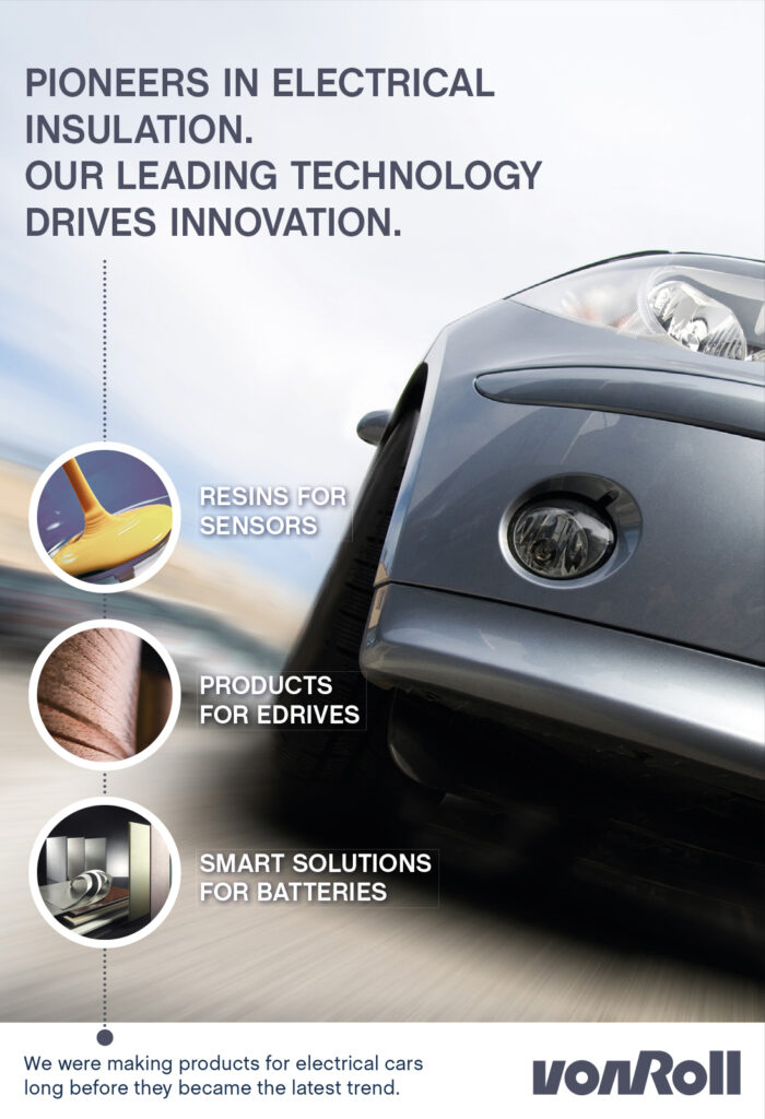
(Courtesy of Laird)
While every design is considered fully individual, this means the system gets better at solving the design challenges with each project. Where a design now takes a day, for example, 18 months ago it would have taken a week.
The current focus of the CFD tool is on individual components such as heat pipes or heat sinks, rather than combinations of subsystems, but it can still provide system benefits.
For example, for an electric car with a motor in each wheel, the limiting factor in acceleration and top speed is the heat of the power electronics and the motor.
Redesigning the cooling for the motor means the car can be driven for longer at top speed. The new design could be 30% more efficient and use a much lower pressure, meaning a less powerful pump can be used and the whole system can be 3D-printed.
Substrates
The challenge of getting the heat away from the electronic components to the heat sinks remains significant, and is an increasingly important design consideration.
Thermal management is a critical consideration in the design of DC power supplies, inverters, power conversion systems and electric motor control applications, and becomes especially significant in the automotive industry as electric traction systems are progressively introduced. There are two main ways to dissipate heat from the components in these systems – by conduction into the printed circuit board (PCB), or convection into the local environment (discounting radiation).
Conduction through the PCB is generally the most efficient, and although standard boards provide good electrical insulation, they are generally good thermal insulators as well, so substrates have to be re-engineered to remove the heat.

(Courtesy of Diabatix)
Bonded external heat sinks, multilayer substrates of copper and Invar (a nickel-iron alloy) with internal heat pipes and single or multiple internal heat planes built of copper or aluminium are all options for thermal management.
Heat can be dissipated from semiconductor devices in quad flat nolead packaging by mounting them on thermal pads connected to copper planes within the circuit board by thermal rather than electrical connectors (known as vias).
Many power electronics devices for electric vehicles are built on direct-bonded copper (DBC) substrates because of their strong thermal conductivity. They are based on a ceramic tile (commonly alumina) with a sheet of copper bonded to one or both sides by a high-temperature oxidation process.
The top copper layer of the DBC substrate can be formed before firing or chemically etched to form an electrical circuit, while the bottom copper layer is usually kept plain so that it can be soldered to a heat spreader.
Beryllium, silicon nitride and aluminium nitride are more effective heat conductors than alumina, but cost far more. Thickfilm technology offers greater design freedom than DBC, but it may also be more expensive.
Multi-layered thermal printed circuit board designs are now providing higher thermal performance to address designs that previously had to use these ceramic substrates.
The key element of an insulated metal substrate material is the thermally conductive dielectric layer between the copper foil and the aluminium plate. It may be a woven-glass reinforced resin composite, called prepreg, as in a conventional laminate construction, or a layer of unreinforced resin. The resin itself is typically a halogen-free epoxylaminating resin.
Conventional FR4 laminate material has very poor thermal conductivity, but the conductivity of the resin component can be significantly improved by loading it with up to 70% of a thermally conducting ceramic filler. However, the resin must also continue to serve the fundamental purpose of reliably bonding the insulated metal substrate construction together under potentially severe thermal-cycling conditions.
Electric power steering and other motor-driven mechanisms, including high-power electric traction inverters, have even tougher thermal management challenges, requiring substrates with a thermal conductivity of 3-4.2 W/mK and 0.10-0.15 mm (0.004-0.006 in) dielectric.
(Courtesy of AT&S)
In extremely high-power applications such as inverters, power transistors may be soldered to the insulated metal substrate (IMS) or DBC layer as bare die, and a liquid-cooled heat sink attached to the baseplate. In some modules, such as combined onboard charger and DC-DC converter units, this baseplate is integrated with a cast metal chassis to remove the heat.
These IMS technologies are also being used in the battery pack. The connections between cells can now include more monitoring devices such as temperature sensors on an IMS substrate, and there is a wide range of materials that can be used in the layers of IMS boards.
Construction
When the battery packs and traction motors are assembled, there is still demand for heat-conducting pastes to help minimise hotspots. These viscous materials contain a high proportion of abrasive ceramic fillers, which makes their efficient application a
challenge and leads to low dispensing speeds. This can cause a bottleneck in automated production processes for building electric vehicles.
The design of the paste delivery systems for the encapsulation of battery packs is itself an engineering challenge.
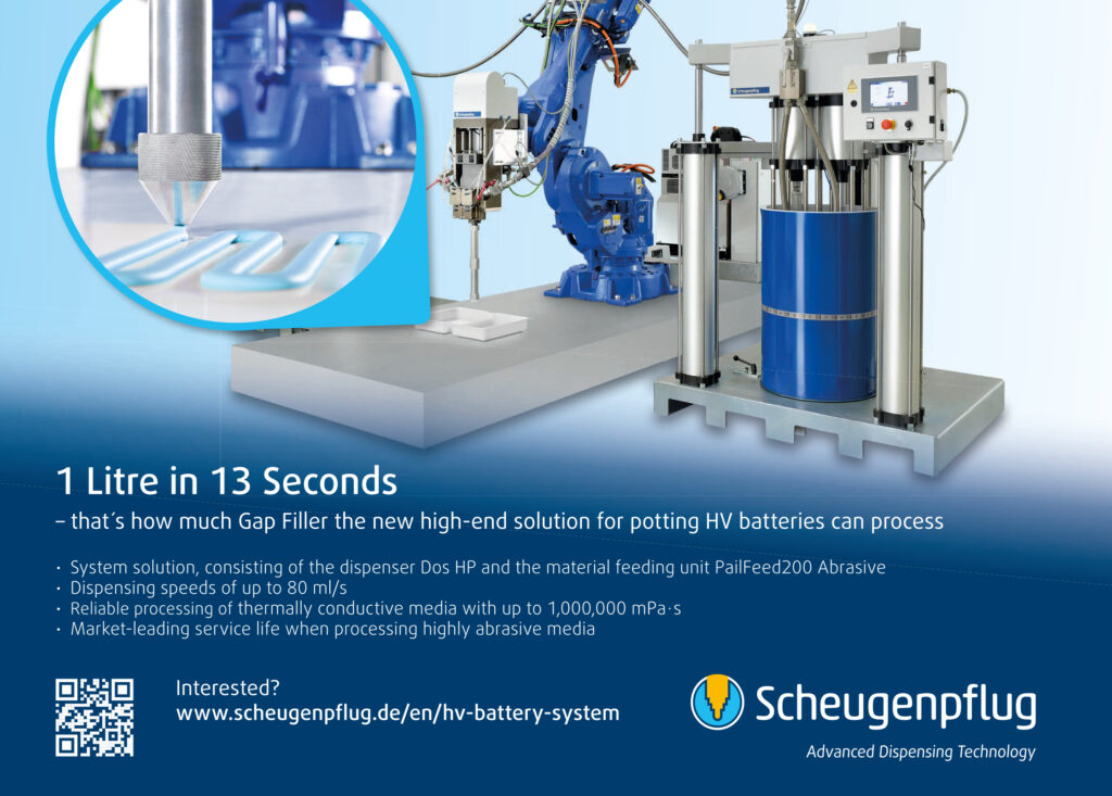
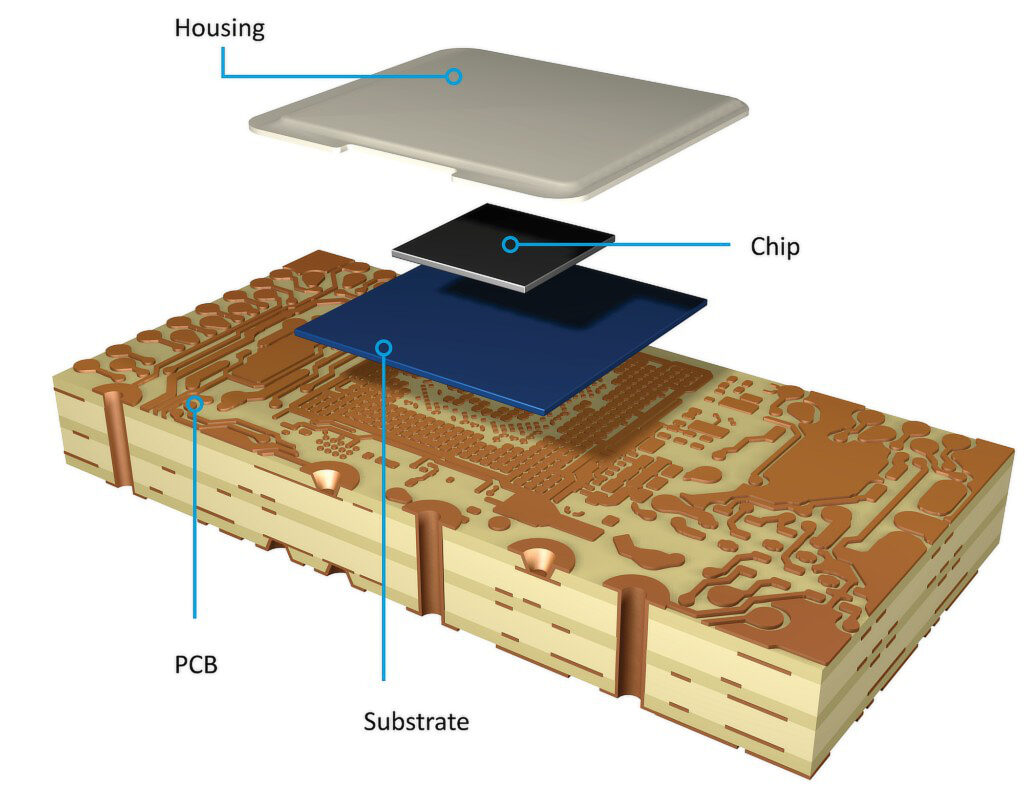
High-speed dispensers with a material feeding system can now deliver paste at rates of up to 80 ml/s and with high levels of accuracy. A dispenser with an integrated doublepiston pump can provide a volume of 480 cm3/stroke, which allows for a continuous material feed via a robotic arm that can reach across the whole battery pack thanks to a high delivery pressure of 65 bar.
Moving thick abrasive material at speed on the factory floor is also a challenge, as the material can be difficult to handle, so only one side of the pump comes into contact with the thermal material. The rear side contains a barrier fluid, which prevents abrasive fillers accumulating on the seal and pump components.
From optimising the design of the individual heat pipes and heat sinks to the construction of the substrates holding high-power components, there are many options for maintaining a constant thermal envelope for a ground or air vehicle.
(Courtesy of Scheugenpflug)
The boost in processing performance for design tools is helping to net significant gains for the manufacturing of the components, and new materials are helping to move heat energy effectively through the system.
Building the vehicle platform also requires consideration. Effective, accurate and high-speed application of thermal pastes can help battery packs stay at the optimum temperature and avoid calamitous failures, but new delivery systems have had to be developed to support automated manufacturing.
Acknowledgements
The author would like to thank Lieven Vervecken and Hans Klass at Diabatix, Didier Mauve at Ventec International, Ryan Maughan at Avid Technology and Christian Ostermeier at Scheugenpflug for their help with researching this article.
ONLINE PARTNERS

