


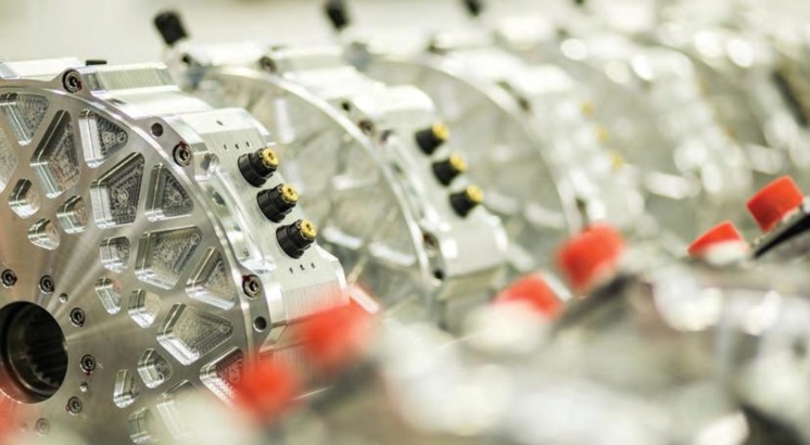
Axial flux motors
(Courtesy of YASA)
Axial flux motors have many EV design advantages over their radial flux counterparts, as Nick Flaherty explains.
Axis of power
A new type of motor is gaining traction in the e-mobility sector – the axial flux type. For many years they have been used in stationary applications such as elevators and agricultural machinery, but over the past decade a number of developers have been working on improving the technology to make it suitable for applications such as electric motorcycles, airport pods, delivery trucks, electric cars and even aircraft.
Traditional radial flux motors, which use permanent magnets or induction motors in an electric field, are undergoing extensive development aimed at optimising their weight and cost. That can only go so far, however, so moving to a completely different machine type such as axial flux might be a good alternative.
Axial flux permanent magnet machines typically provide more torque for a given volume of motor than a radial motor, as the active magnetic surface area is the face of the motor’s rotor rather than the outside diameter.
That makes axial flux motors much more compact; the axial length of the machine is much shorter compared to radial machines, a factor that is often crucial for an application such as an inwheel motor. The slim and lightweight structure results in machines with a higher power and torque density than a comparable radial machine, without the need to resort to very high speed operation.
Axial flux motors can also be highly efficient, with efficiencies typically over 96%. That comes from the shorter, one-dimensional flux path, which is comparable to or better than the very best 2D radial flux motors on the market.
The motors are shorter, typically by five to eight times, and can be two to five times lighter. Both these factors change the options for electric vehicle EV platform designers.
Axial flux technology
There are two principal topologies of axial flux motor – dual-rotor singlestator, sometimes called torus-style machines, and single-rotor dual-stator.
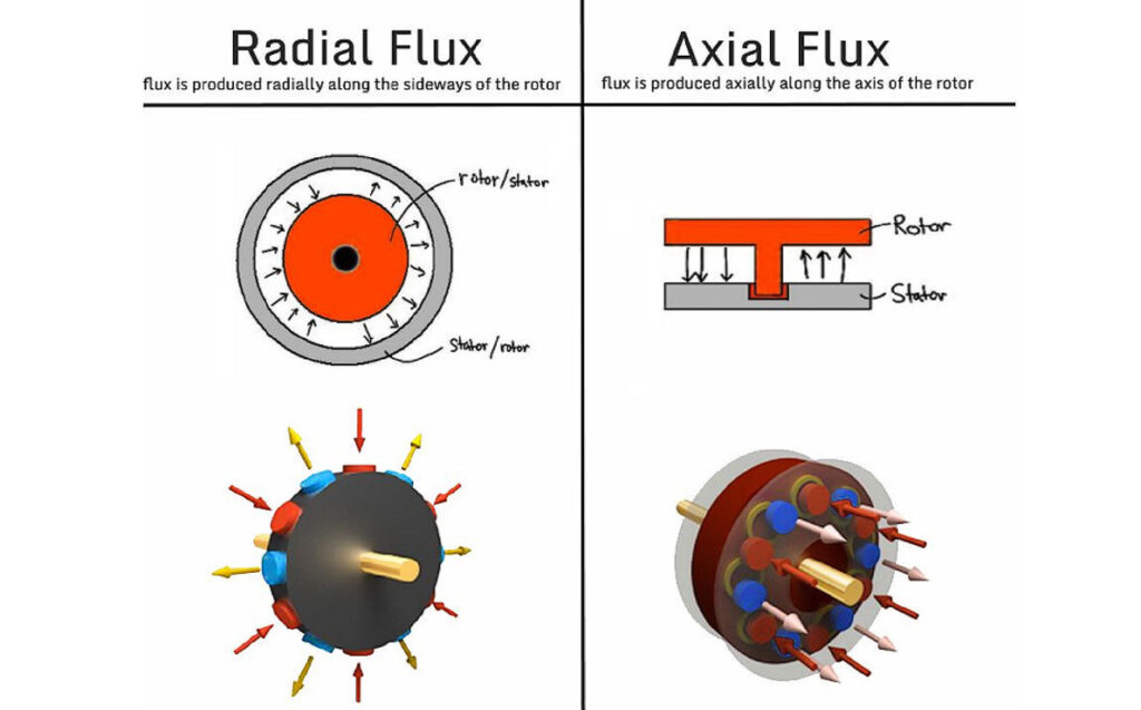
Most permanent magnet motors these days work with a radial flux topology. Here, the magnetic flux loop starts at a permanent magnet on the rotor, passes through the first tooth on the stator, then flows radially along the stator. It then passes through a second tooth to arrive at the second magnet on the rotor. In a dual-rotor axial flux topology, the flux loop starts at the first magnet, passes axially through a stator tooth, and immediately arrives at the second magnet.
That means the flux path is much shorter compared to that in radial flux machines, allowing the motor to be smaller for the same power, and have a higher power density and efficiency.
By contrast, in radial motors the flux moves through the first tooth and then via the stator back to the next tooth to the magnets. It also has to follow a two-dimensional path.
Because the flux path in axial flux machines is one-dimensional, grainoriented electrical steel can be used. The steel makes it easier for the flux to pass through, and this results in the efficiency gain.
Radial flux motors have traditionally used distributed windings, where as much as half the winding are not active as they overhang the magnets. Designs have improved winding methods, as the coil overhang results in additional weight, cost, electrical resistance and more heat wasted.
Axial flux machines have far fewer coil overhangs, and some designs use concentrated or segmented windings that are fully active. Segmented stator radial machines introduce additional loses owing to breakage of the flux path in the stator, but that is not a problem for axial machines. The design of the coil windings is a key area where suppliers can differentiate between themselves.
Development
However, axial flux motors pose some serious design and production challenges that have made them far more costly than their radial counterparts, despite the technological advantages. Radial motors are well-understood, and manufacturing methodologies and machinery are readily available.
One major challenge with axial machines is maintaining a uniform air gap between the rotor and the stator, as the magnetic forces are much higher than in radial machines. Dual-rotor axial machines also have thermal issues, as the windings are located deep within the stator and between the two rotor discs. That makes it difficult to dissipate the heat.
Axial flux motors have also been difficult to manufacture, and for several reasons. Dual-rotor machines with a yokeless topology (where the iron yoke of the stator is removed but the iron teeth are kept), overcome some of the problems while avoiding the need to scale the machine’s diameter and magnets.
Removing the yoke introduces new challenges though, such as how to fix and position individual teeth without the mechanical yoke connection. Removing the heat is more of a challenge as well.
Producing the rotor and maintaining the required tolerance on the air gap can also be difficult, as the rotor discs exert an attractive force on the rotor.
The discs are directly connected to each other via the shaft ring, however, so the forces cancel each other out. That means the internal bearing does not carry these forces, and its only function is to keep the stator in the middle, between the two rotor discs.
Although dual-stator single-rotor machines do not face the challenges of the torus machines, the design of the stator has been much more complex and difficult to automate. Since it’s unlike any traditional radial flux machine, the manufacturing processes and machinery simply did not exist until recently.
Accommodating the airgap in the build of the machine has also been difficult, as it requires precise control of the manufacturing tolerances of key components. That has led to a far more complicated stator design, making automated and volume production difficult and keeping the cost of the motors high.
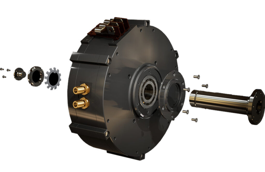
(Courtesy of Magnax)
Electric cars
Reliability is paramount in the automotive industry, and providing evidence of the reliability and robustness of the different axial flux motors to convince manufacturers of their suitability for mass manufacturing has been a challenge. That has led axial motor suppliers to carry out their own extensive validation programmes, with each being able to demonstrate that the reliability of their motors is no different from that of traditional radial flux types.
The only parts in axial flux motors that experience wear are the bearings. They are positioned much closer together owing to the relatively shorter length of the axial flux design, and are also typically slightly ‘over-dimensioned’. Furthermore, the lower-mass rotors in axial flux machines are subject to lower rotordynamic shaft loads, so the actual forces exerted on the bearings are much lower than in radial flux motors.
One of the first applications for an axial motor is the e-axle. The thinner width allows the motor and a gearbox to be packaged in the axle. In hybrid applications, the motor’s short axial length in turn keeps the overall length of the drivetrain short.
The next step is to put the axial motor in the vehicle wheel. This allows the power to go directly from the motor to the wheel, increasing the motor’s efficiency. The complexity of the system is also lower, as the transmission, differentials and driveshaft are eliminated.
However, no standard configurations appear to be emerging. Each OEM is looking at specific configurations, as the different size and form factor of the axial motor changes the design of an EV. The motors’ higher power density means that a smaller axial motor can be used compared to a radial motor. That opens up new design options within the vehicle platform, such as where to place the battery packs.
Flux efficiency
Grain-oriented steel cannot be used with radial flux machines because the flux paths in these machines follow a non-linear 2D path. In a yokeless axial flux topology, the grains of the steel are oriented in the same direction as the flux paths, so a more efficient grain-oriented electrical steel can be used for the core. The low losses and high level of permeability of the grainoriented material in the rolling (axial) direction reduces stator core losses by 85% and gives a slight increase in the electromagnetic torque.
One way to boost the power of an axial motor is to combine multiple machines in a stack within a single, water-cooled housing. This gives a lot of flexibility in the design for a given application, and allows a more standardised production technique.
Some e-mobility applications require direct-drive motor concepts. A gearless design significantly reduces complexity and maintenance requirements. This maps well to axial flux motors that already deliver the nominal torque at zero rpm. For in-wheel designs, the efficiency is optimised for lower rpm ranges, usually with wheel speeds between 400 and 2000 rpm.
Only the active parts (the stator and two rotors, for example) can be integrated inside OEM powertrain concepts. In e-axle systems, the smaller volume of the motor can provide compact powertrain designs in the OEM market.
(Courtesy of YAGA)
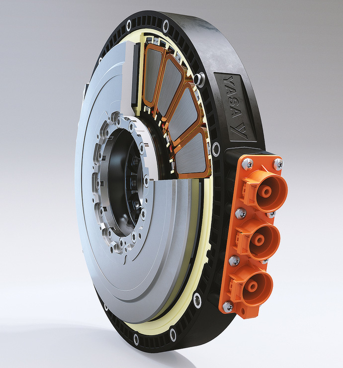
Segmented armature
The YASA (Yokeless And Segmented Armature) motor topology is an example of the dual-rotor single-stator topology with reduced manufacturing complexity for automated volume production. These provide power densities up to 10 kW/kg at speeds of 2000-9000 rpm.
This uses a specialised controller that provides 200 kVA to the motor. The controller takes up a volume of 5 litres and weighs 5.8 kg, which includes thermal management with dielectric oil cooling, and is suitable for use with axial flux motors as well as induction and radial flux motors.
This gives electric car OEMs and Tier 1 developers the flexibility to choose the right motor for the application and the space available. The smaller size and weight allow a lighter vehicle and more batteries, boosting the range.
E-bikes
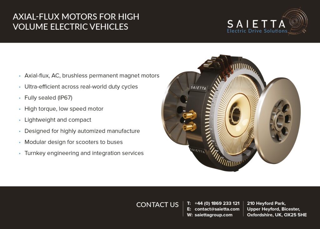
For electric motorbikes and quadbikes, a different design of AC axial flux motor has been developed. It evolved from previous DC brush-based axial flux designs, moving to AC and a fully sealed brushless design, and has been designed from the ground up for volume manufacturing.
Going from DC to AC, the design has coils that are kept stationary, and dual rotors with permanent magnets rather than a spinning armature. The benefit of this approach is that it avoids the need for mechanical commutation.
The AC design also allows the standard three-phase AC motor controllers in radial motors to be used for the axial versions. That helps to reduce costs, as the controller provides the current that controls the torque rather than the speed. The controllers need a frequency of over 12 kHz, but that is now a mainstream frequency for these devices.
This higher frequency comes from the lower inductance of the windings, of 20 µH. The frequency controls the currents to minimise current ripple and ensure as smooth a sinusoidal signal as possible. This is good from a dynamic perspective, as it allows the torque to change very quickly, allowing smoother control of the motor.
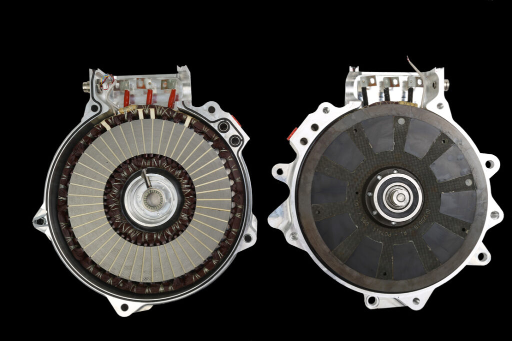
This design uses a distributed doublelayer winding, so the flux is flowing from the rotor through the stator to the other rotor, again with a very short path for higher efficiency.
The key for this axial flux motor design is that it works with voltages up to 60 V, rather than higher voltage systems. That makes it suitable for electric motorbikes and the L7e class of heavy quadricycles such as the Renault Twizy.
The 60 V maximum voltage allows the motor to be integrated into mainstream 48 V electrical systems, and keeps the maintenance simpler.
(Courtesy of Saietta)
The L7e quadbike specification, from the European Framework Directive 2002/24/EC, is for a weight of up to 600 kg for vehicles intended for carrying goods, not including the mass of batteries. They can carry a payload of up to 200 kg for passengers or 1000 kg for goods, with an engine power of 15 kW. The distributed winding approach provides 75-100 Nm of torque with a peak output of 20- 25 kW, providing the 15 kW continuous power.
With axial flux the challenge is to get the heat out from the copper windings, which is difficult as it has to get past the rotors. The distributed winding is key to this, as there are a high number of slots for the poles. This gives more surface area between the copper and the housing to allow the heat transfer to the outside, where it can be extracted by a standard liquid-cooling system.
The multiple poles are key for making use of the sinusoidal waveform, which helps to reduce the harmonics that occur when the waveform is not perfectly sinusoidal. These harmonics manifest as heating of the magnets and core, which cannot be reached by the copper elements to carry the heat away. As the heat builds up in the magnets and the core, the efficiency falls, which is why optimising the waveform and heat path are critical to the motor’s performance.
The motor’s design is also being optimised for lower-cost, automated high-volume production. An extruded housing ring reduces the material cost with no complex machining. The coils are straightforward to wind, and use a bonding process during winding to keep them in the correct shape for the assembly.
A key point is that the coils are made from standard, commercially available wire, and the core uses standard laminated off-the-shelf transformer steel that just needs to be cut to shape. Other motor designs require soft magnetic materials in the lamination for the core, which can be more expensive.
Using distributed windings means the magnets don’t need to be segmented; they can be simpler shapes that are easier to make. Reducing the size of the magnets and making sure they can be easily manufactured has a major impact on reducing the cost.
This axial flux motor design is also being offered on a customised basis. The customer then owns the custom version developed around the base design. This is then built on a pilot line to prove the early volumes, and the line can be copied in other factories.
The focus on customisation is because the performance of the vehicle depends as much on the quality of the vehicle architecture, battery pack and BMS as on the design of the axial flux motor.
(Courtesy of Saietta)
The design will scale up with multiple rotors in a single, cooled housing, but the limit here is the amount of current that can be used. That means the controller and the BMS are the bottleneck. Going to lower power, the bottom end of the range for the motor is 4-6 kW.
The motor can also be used for marine applications, as it is fully sealed. This is already of interest as the onboard motor for yachts to save space and weight, and there is interest from outboard motor makers as well.
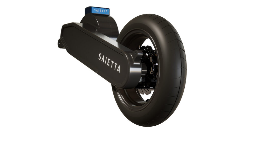
However, for the electric motorbike market one of the major drawbacks is the challenge of charging the bikes quickly and easily. An axial flux motor helps here as it can be integrated into the swing arm with the battery, so that it is attached to the frame of the bike with a bolt, making maintenance and replacement much simpler.
Some electric motorcycle makers are also looking at modular cassette batteries, particularly in China and Thailand, where depleted batteries can be swapped out for charged ones. In this case, the ease of replacement is key and the pancake shape of the motor allows it to sit naturally in the frame of an electric motorcycle, leaving more space for the battery pack.
Buses and trucks
An existing axial motor design is being optimised for use in large electric trucks. A cost reduction of the existing design with a dual-stator single-rotor, distributed winding and a yoke with a spiral-wound laminate steel stator core can provide 440 kW, which is enough for a 38 tonne truck.
A new version of the motor will see incremental improvements around the stator, particularly using thin steel for the laminate. Rather than using an externally formed slot-inserted winding, which is labour-intensive, the new version is looking at ways to go to an automated design.
With radial flux motors the cost of the magnets, steel and copper, and conversion cost – the processes for high-volume production – is well-established. The problem with axial flux motors though is that the processes are not understood at scale. The input costs can be reduced but the conversion costs are not wellestablished and so can be highly variable.
In principle, an axial flux motor can be competitive with the radial version through lower material costs for a given power-to-weight ratio, but the conversion cost is the big factor.
E-axles
The pancake shape of the axial flux motor lends itself to integration in a wheel, creating an in-wheel motor, and there are several projects looking at how that might be achieved in harsh environments.
Another approach is to use axial flux motors in e-axles. These have similar issues to in-wheel designs but are simpler to implement, especially in electric trucks that already have a live rear axle.
Putting the motor on the axle adds weight and complexity though, so the motor has to be robust and reliable. The lightest possible motor will give benefits in e-axle designs for small-tomedium delivery trucks and smaller local bus designs.
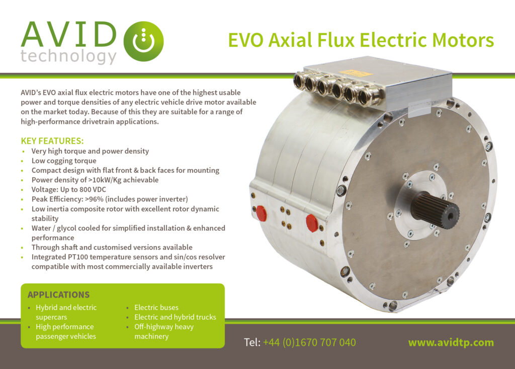
An axial flux motor developed for large trucks
(Courtesy of Avid)
Electric aircraft
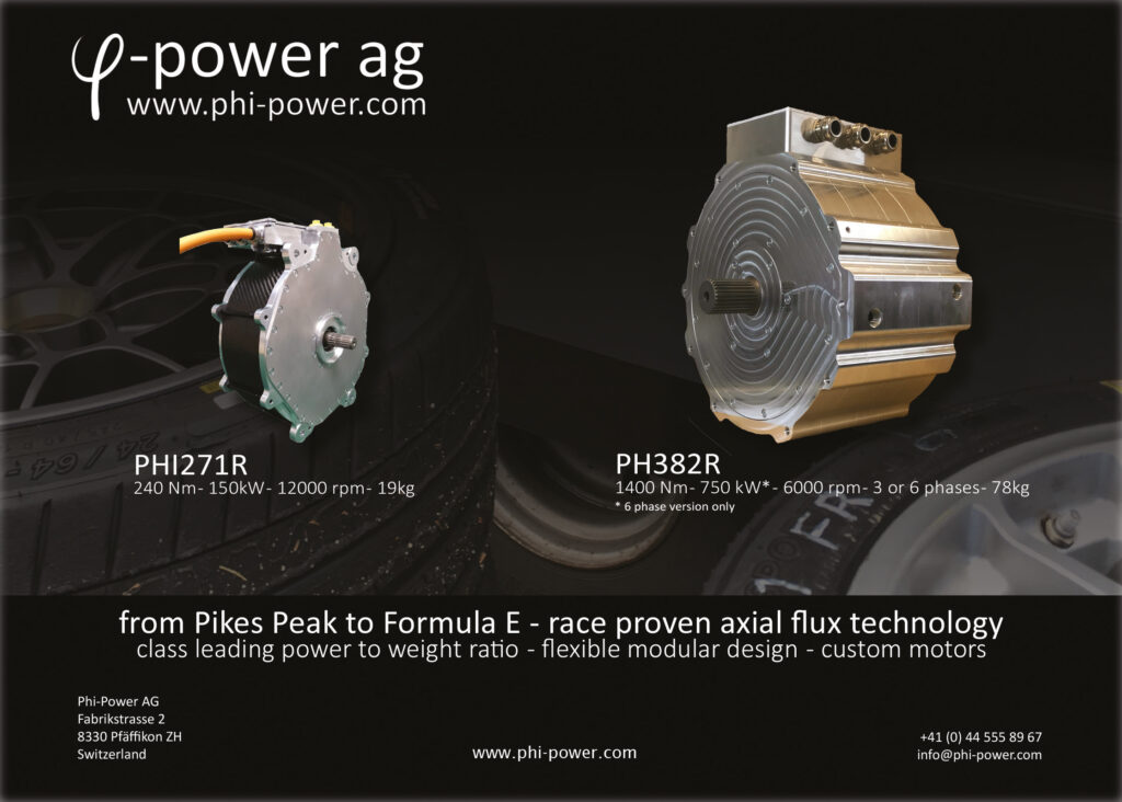
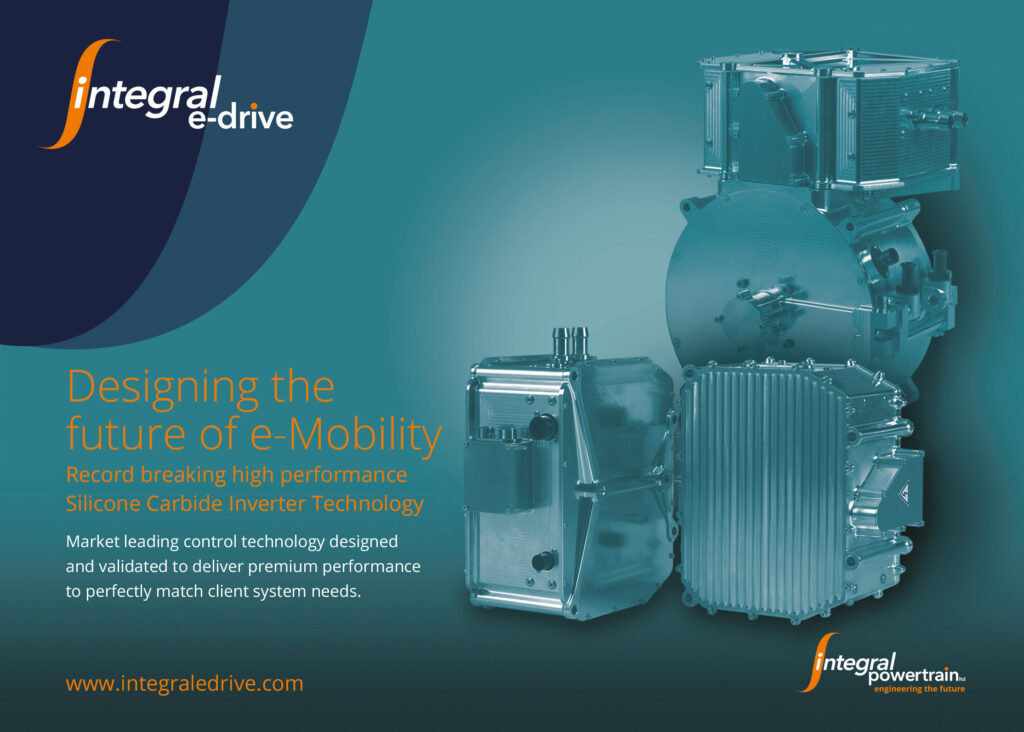
Yokeless axial motors are also at the heart of the development of small electric aircraft. The ACCEL zeroemissions plane for example has a target speed of 300-plus mph (480-plus kph). Three axial motors generate 500 hp to drive three propellers at 2400 rpm. More than 6000 battery cells provide 750 kW to power the motors through a 750 V inverter that was developed for Formula E racecars.
Another approach for axial motors for aircraft uses a carbon composite rotor, which avoids having to use iron or ferrous materials, with the embedded magnet being held by carbon fibre tape. This is bordered by two stators either side of the rotor, rather than the conventional use of just one. The cooling system for the stators has been designed to allow a completely sealed unit.
The system also avoids using any external moving parts and reduces the wiring complexity, as the control electronics can be built into the motor. Current versions weigh from 82 kg for a 440 kW motor to 22 kg for a 100 kW motor; a 5 kW motor weighing less than 750 g is also under development.
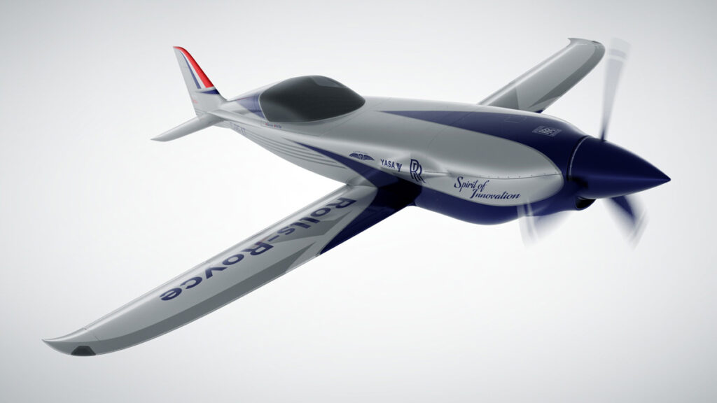
(Courtesy of Rolls-Royce)
Looking ahead
Axial flux motors have a wide range of potential applications, and are being optimised for different power levels, power densities and cost points. There are always opportunities for the highest power-to-weight ratios, particularly in electric aircraft, but there are increasing opportunities at the low end in electric motorbikes.
The next phase of electric passenger and cargo vehicle designs will focus much more on lower weight, and this is a key opportunity if the costs can be reduced.
The challenge is that existing permanent radial flux and induction motors are also being optimised for cost, so the target is always moving. Axial flux motors use less material and so are intrinsically less expensive if the heat transfer and volume manufacturing challenges can be solved.
These can deliver a power density of 10 kW/kg, which is four times the power density of a radial flux motor for an electric vehicle. That means less copper and steel is needed with smaller magnets, all reducing the cost. The lighter weight also saves system cost within the vehicle.
Acknowledgements
The author would like to thank Daan Moreels at Magnax, Wichter Kist, Chris Lines and Graham Lenden at Saietta, and Ryan Maughan and Dhillibabu Palani at Avid Technology for their help with researching this article.
ONLINE PARTNERS
