


Electric & Hybrid Vehicle Technology Expo 2018
Lawrence Butcher rounds up some of the innovation highlights at this show – the largest such event in North America.
The annual EV and Hybrid Technology Expo returned to Novi, Michigan, in September 2018, with a host of companies displaying a range of products and technologies related to the EV market. The event also incorporated The Battery Show and the Critical Power Expo, which featured mobility solutions and grid related technology.
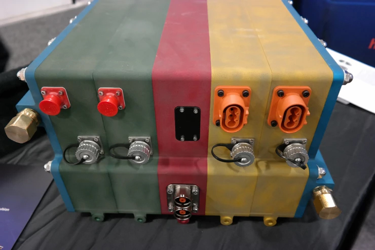
Medatech, a producer of heavyduty EV traction solutions, was showcasing its products developed for the mining and off-highway sectors, most notably battery packs and power electronics.
Explaining the growth of interest in EV systems in mining, David Lyons told us, “It is a huge market for EVs, and specifically with mining, the cost justification is right there when it comes to ventilation systems. With diesel engines, you spend a ton of money getting exhaust out and air in [to the mines]. With electric you remove that cost.”
The operational requirements for underground mining equipment are certainly severe and, as such, Medatech’s products could best be described as rugged – unsurprising, given the size of machinery used.
Medatech was displaying its heavy-duty battery and power electronics systems for mining applications
Lyons said, “On the larger machines you will have two or three battery packs to power a 70,000 lb truck.” The packs in question give a total output of around 150 kWh on the largest vehicles, and the power output of the larger dumper trucks is around 200 kW.
“At the extreme end though, where you are talking about a 100,000 lb truck, it is about 350 kW,” he said, adding that most of its systems run at around 750 V.
While the battery capacity might seem quite modest, given that some road vehicles have systems of similar capacity, Lyons highlighted that the company’s performance edge comes from a fast charging rate.
“Full-electric buses are running 300 kWh batteries,” Lyons said. “On a 70,000 lb truck you are talking 90 kWh, but we have a very powerdense chemistry – we are charging at 3 C and beyond and outputting at 1.5 C.
“One of the biggest challenges is thermal management. You can’t just go and use a lead-acid, aircooled battery in 50-degree heat, underground [Medatech uses lithiumion chemistries].”
Lyons said he feels there is great scope for the adoption of EV technology in mining. “There is one allelectric mine in the world right now, in Canada, and 80% of the BEVs [Battery Electric Vehicles] there are our systems and have been running for three years.
“There are areas in the wider EV industry that could use our technology and efficiency – waste management vehicles, for example. That is an area that hasn’t been tapped into yet. But mining is the area where we are really having a lot of success.”
Wieland had its latest motor technology, a fabricated copper rotor, on display. Julian Clamroth said, “It is fabricated, not die cast, so it allows us to create some unique architectures.
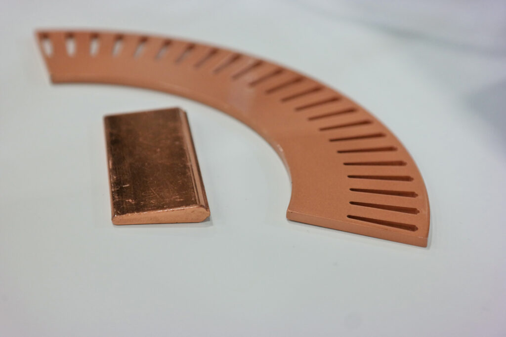
Segments of Wieland’s copper rotor
“We use a radial laser welding process to connect the busbars and the different rotor discs. The big advantage with this approach is that we can combine different materials in the end rings. We can use pure copper for good conductivity, or combinations of different copper alloys for improved mechanical properties.”
This ability to mix materials allows for rotors to be built that have excellent electrical performance as well as the mechanical properties to withstand use at high speeds. “Depending on the specifications and dimensions of the rotor, we can reach up to 25,000 rpm, which gives a surface speed of about 140 m/s on the rotor,” Clamroth said.

Cross-section of the liquid-cooled cable from Huber and Suhner’s fast- charging point
The rotors made using Weiland’s method do not need containment rings or other structures, making them simpler to manufacture than traditional designs, said Clamroth. Also, the process of extruding the rotor bars and laser-welding the structure is fully automated, making it feasible for mass-production applications without excessive cost.
Wiring specialist Huber and Suhner had its latest generation of charging connector on display, dubbed the Radox High Power Charging System, which can handle charging rates of up to 500 kWh.
“When we started this project, the target given to us from the car manufacturers was to have the same feeling when charging a car as filling it at a gasoline station,” explained Max Goldi, who led the development of the system.
“So the weight, touch, feel and flexibility of the cable should be the same as a fuel hose. We also had a benchmark time of 15 minutes’ charging time to 80% of the battery capacity.”
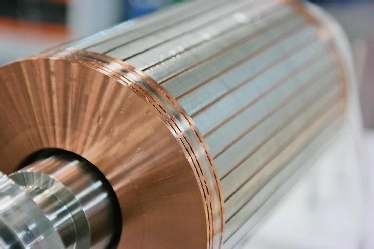
The welded copper rotor displayed on Wieland’s stand
The maximum capability of present charging systems is around 150 kW, running currents up to around 150 A. “It was suggested that the next target should be 350 A, but we said, why limit it, let’s go to 500 A,” noted Goldi. “A traditional cable able to accept a sustained 500 A current would be very heavy gauge and unwieldy, however, which would not fulfil the brief of feeling like a gasoline fuel hose.”
The company’s answer was to cool the cable and connector. ”We bring the coolant right to the front of the connector, cooling directly at the pins as that is the most critical point,” said Goldi. The pins have an internal coolant channel, and the coolant – a dielectric fluid – is run directly along the surface of the copper cables, in a channel between the wire and the insulation material.
“The beauty with the dielectric coolant is that even if something goes wrong – if the coolant leaked into the electronics, for example – it would make a mess but would not be the end of the world,” noted Goldi.
The cables are sized at 25 mm2, although as Goldi recalled, “We actually started out at 16 mm but standards have levelled out at 25 mm. It is always a balance – the smaller you go, the more flexible the cable, but then the smaller the conductor, the more energy you burn [as rejected heat] as you have to cool it more.”
Huber and Suhner will supply charging station manufacturers with the complete cable assembly and an interface for integration into a charger. “The supplied system includes a small tank, which has up to 5 litres of coolant, and a heat exchanger that will work even in 40 C heat. You can also use an external water-cooling system, but the preferred option is the liquid-air cooler, as water and power do not go well together,” said Goldi.
While Huber and Suhner has created a connection solution to allow for high-rate charging, Goldi pointed out that the maximum most on-vehicle connectors can accept is 200 A. “Porsche and Audi are moving to 800 V systems and probably 300-350 A, so development is progressing in that area,” he said.
He also mentioned that some manufacturers are investigating the use of the cooled cables for on-car applications. “We are talking to some people but there is nothing concrete yet,” he said. “The biggest challenge [to increasing charging rates] is still the battery system.”
BAE Systems was displaying its modular power electronics systems, which provide a scalable solution for traction and accessory drives for electric and hybrid applications. Of particular note was its IAPS (Independent Accessory Power System) designed for use with conventionally powered, hybrid or EV vehicles that rely on electric power to drive subsystems such as air conditioning and airbrakes.
“Right now we have a single, integrated system that is very high power – 60 kW – from which you draw power and distribute it [to the various systems],” explained Derek Matthews. Moving to a modular system, where each accessory is handled by its own dedicated power module, makes for a more scalable and reliable system.
He pointed out that with an all-inone system, one subsystem failure could disable any other systems using the same power source. “Say your aircon goes down, that means you lose the airbrakes as well [using the older system]. With the IAPS though, if one element breaks down, you can still keep the system running. It also means you get only what you need in terms of capacity, and can have much better control over power delivery.”
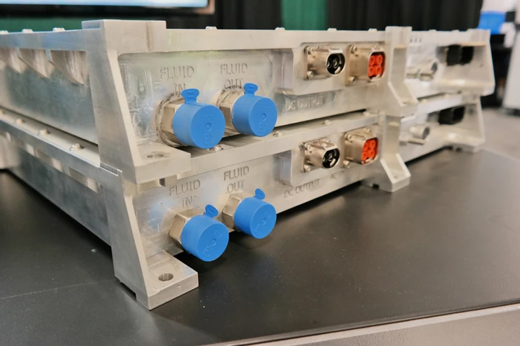
BAE Systems’ modular accessory power unit using SiC power electronics
Matthews explained the layout of the IAPS modules. “Each DC-DC converter is 200 A; put two together and you can have 400 A. Then you might say you need to run an aircon compressor; you can have a three-phase output for that. If you want to run an airbrake compressor, there is an output available for that as well.”
The modules can be stacked together, with each one sized to suit a given accessory. According to Matthews, the IAPS system is one-third the volume of BAE’s previous all-in-one system.
The individual system blocks link together, with a parallel-flow cooling system routed across the back of the units. Matthews said, “Because we use SiC, the heat rejection requirements are quite low. In the past [on its siliconbased systems], we used series flow, because there was a lot of heat to remove, but now the combination of sizing [each block has a lower individual power output than the previous all-inone unit] and SiC means we can use parallel flow.”
On the subject of SiC, the power electronics BAE has used in its heavyduty power electronics to date have been silicon-based, but now, according to Matthews, “We are moving to silicon carbide for all our traction systems. That helps a lot with both efficiency and packaging.”
Interestingly, Matthews noted that although the cost of silicon carbidebased electronics is higher than silicon, “You get a lot of savings in other components, which almost negates that cost delta. OK, so a silicon-based switch is $200 and the SiC one is $800, but if you look at the other parts of the package – the size of the cold plates, the amount of material used – all of a sudden you have a lot less ‘stuff’. So the peripherals work out less.”
He highlighted that for BAE and its customers, cost is calculated predominantly on the basis of kWh per kilometre. “That metric is the one everyone wants to know, so we need to make the most efficient system out there. The key is that motors and the like are getting cheaper, while batteries still cost a lot, so we need a solution that allows customers to buy fewer batteries for the same performance level.”
Matthews said there is no single ideal solution for all applications, but because BAE has control over all the components in its powertrain offerings, “We are constantly doing trade-offs between different elements of a system to get the best solution.
“Take coolant flow rates for example. If one element needs only 5 litres/ minute and another needs 50, I need to look at how I can achieve that without needing two systems.
“Finding efficiency even gets down to elements as subtle as the wire sizes. When you are pushing for a set power level, if you can drop the current at which that is achieved – and thus allow a reduction in wire size from, say, 100 to 50 mm2 – you save the customer a lot of money. It’s lighter, is easier to install and so on. You have to think about the entire system.”
The Rolled Ribbon Battery Company was displaying its unique battery format
Volumetrically and in terms of mass, batteries constitute the most sizeable element of an EV drivetrain. Therefore, any steps that can be taken to offset the impact of that mass on overall vehicle package weight are desirable. One approach, advocated by Cape Bouvard Technologies (CBT), is to use batteries as structural elements, a technology it was showcasing at the Novi Expo.
Central to the design of CBT’s battery is its proprietary ‘ripple strip’ system, which provides heat transfer (via cooling channels in the strips) while also forming the central structure of a pack. The cells of each battery module are bonded to the aluminium strips to form a pack six layers deep, and a coolant tank is bonded to the end of each pack, followed by a BMS module. This forms what CBT refers to as a ‘six-layer assembly’.
Each assembly is then bonded to a composite base structure, which carries coolant and electrical connections. The sides of the battery (which incorporate vehicle-specific mounting structures) are added and the entire battery closed off with a composite top sheet.
The safety of the structural batteries is ensured through a number of redundant systems that control battery temperature, monitor battery state and scan for indications of a fault developing. For example, the pack’s interior is sampled for telltale gases that could indicate cell outgassing.
Also, the cell spacers are made from a phase-change material that can absorb heat, reducing thermal loads on the individual cells, and in the event of thermal runaway of cells in a module, the entire assembly can be purged with coolant.
One booth, that of the Rolled Ribbon Battery company, was displaying what appeared to be giant button cells.
Thomas Mezger explained that the company’s namesake technology involves combining long strips of anode, cathode and separator material around a hub, rather like a Swiss roll. The roll is then sandwiched between a pair of metallic plates, which form the anode and cathode terminals of a cell, with the plates separated by an insulating ring.
A major benefit of this construction, claimed Mezger, is that the edges of the anode and cathode are in total contact with their relative terminals, giving very low electrical and thermal resistance. He noted that this is a particularly significant advantages of this method of cell construction, compared to cylindrical or pouch-type cells, which rely on a relatively small conductor area (meaning less heat transfer to the outside of the cell and greater electrical resistance).
“That allows heat to travel along the electrode foil rather than through multiple layers of electrode material, foil and separator,” he said. “The thermal resistance along an electrode foil is of the order of 100-200 times lower than that for crossing electrode layers.”
Rolled Ribbon Battery’s core competence is in the cell construction, and Mezger said it is chemistryagnostic.
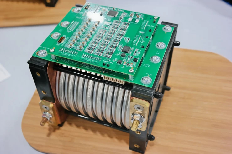
Lionsmart was displaying its integrated battery construction and management system.
“In our approach, each cell has its own control,” explained Joseph Endres. The cells are held in a support structure, with a copper alloy sheet resistance welded to the individual cells. In the example pack on display, there were 84 individual cells attached to a sheet.
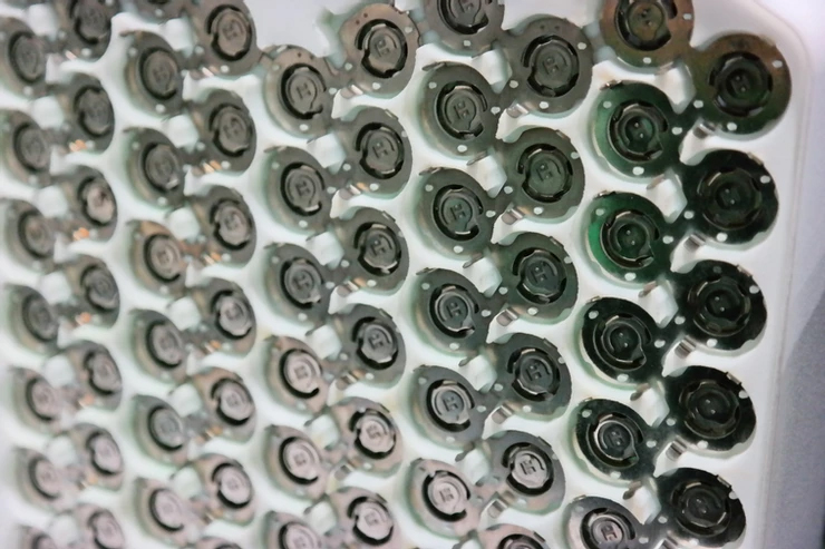
Dukosi’s cell-level BMS system on display
“The sheet has two functions,” he said. “There is a small fuse between the cells and the sheet, and if there is too high a resistance, the fuse will open and the cell will be removed from the system. The sheet also provides a contact to the negative pole of the next cell.”
The cells are connected in parallel, so if one cell drops out, the impact on overall battery pack performance is minimal.
Each cell also incorporates a sensor to measure temperature at the positive and negative terminals, as well as the voltage. Data communication is via an infrared LED system through the battery pack. At the end of the battery pack is a signal processing unit, which translates the LED data into a signal that can be fed to the overall battery management system.
In the demonstration pack, cooling is provided by a dielectric fluid that fully immerses the cells (in this case 3M’s Novec fluid). The fluid also provides protection against thermal runaway if a cell is overheating.
Endres said the capacity of batteries built using its system is around 230 Wh/kg and about 400 Wh/litre. “It is a unique approach that you can scale to any size,” he said.
Battery specialist Dukosi was displaying the latest iteration of its innovative battery management technology. Centred on an ASIC chip, it has been designed to provide individual control and monitoring of cells in a battery pack.
In Dukosi’s system, each cell is equipped with its own controller, which uses an RF connection to communicate with a receiver in each battery module or pack. Up to 175 individual cells can be accommodated on each channel, explained Josh Letworthy. “The system is endlessly scalable for any configuration, size or type of pack,” he noted.
The embedded chip and its operating software allow the monitoring of cell temperature and voltage to be monitored, as well as a cell’s characteristics to be modelled over the long-term.
In effect, every cell in the battery can be monitored and its performance tracked through its entire life, an aspect that Letworthy said is significant given the increasing focus on second-life uses for battery packs.
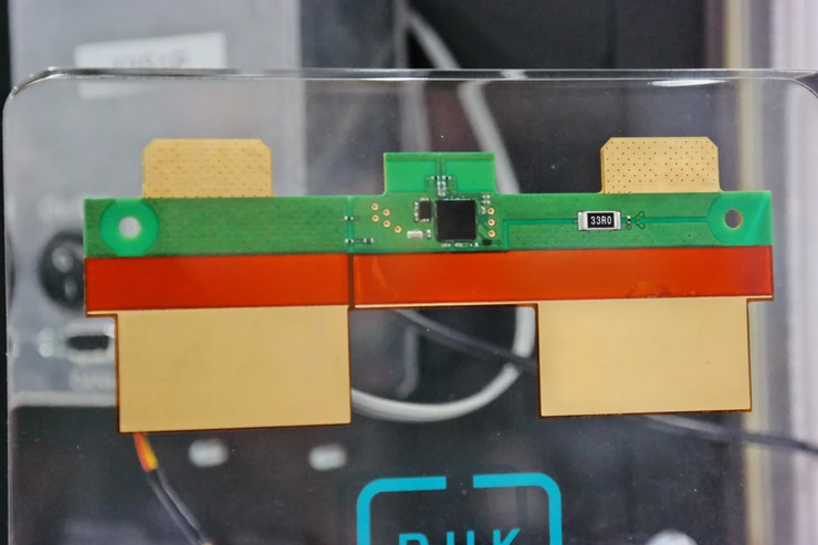
Dukosi’s cell-level BMS system on display
ONLINE PARTNERS
