


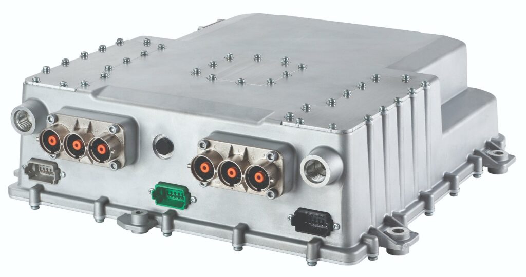
Inverters
(Courtesy of Eaton)
Power by design
Nick Flaherty explains the issues involved in developing inverters for different types of vehicle.
The design of an inverter for an electric vehicle depends very much on the application. Full electric, hybrid, commercial bus and truck and electric motorsport all have different design trade-offs.
Commercial vehicles need high power and long life, while cars need lower cost and the facility for volume manufacturing. Construction equipment may not even have a battery but use electricity directly from a generator. These are very different from a hand-assembled motorsport design that aims to squeeze as much out of the smallest size and lowest weight.
Weight is saved by being minimalistic. If the inverter has been designed to minimise weight it will also be reasonably simple to assemble.
Cooling is the first thing to consider during the design, because the way that is implemented will directly define the shape and size of the inverter. Removing the heat from the switching devices – usually an IGBT or a MOSFET – is effectively the key to optimising the inverter’s performance.
Once the switching modules and cooling have been chosen, there are the busbar layout and gate driver location to consider. The capacitors need some thought too, as they tend to be the heaviest part of the inverter. Unlike the semiconductor components, the capacitors can’t be shrunk, so they have to be integrated into the inverter’s design.
With an inverter there are typically three switching modules, one for each phase. There can be one gate driver per module or a three-phase module with a single driver. Often the inverter maker will work with the semiconductor vendor or module maker on the IGBT or MOSFET module.
The next factor is the operating frequency. Motorsport inverters operate at up to 75 kHz, whereas 10-20 kHz is more common for mainstream passenger vehicles.
There is also a direct correlation between the inverter frequency, the rotational speed of the motor and the vehicle’s maximum speed. The optimum ratio of switching frequency to electrical frequency will depend on motor design, and will need to be optimised for each application.
The aim is to create as ideal a sine waveform as possible so that there is a sweet spot for optimum system efficiency. A higher switching speed means more losses in the inverter, but that has to be offset against an improvement in motor efficiency.
New MOSFETs based on silicon carbide (SiC) support higher frequency operation and higher currents with lower switching losses while operating at higher temperatures. The cost of these MOSFETs is about four times that of IGBTs at the same power level, but their higher performance reduces the size of the inverter and cooling system, reducing the overall weight.
For example, with an IGBT you tend to need two modules in parallel to achieve the required current, which is twice the size of a SiC version. This is driven by higher voltage requirements, with inverters now operating at 800-900 V.
Higher frequency operation also allows smaller capacitors, as there is a reduction in the ripple voltage on the DC side. That has a small but valuable impact.
While film capacitors are the main technology used today, there are several potential solutions for the future, including solid-state types, which would reduce the size and weight, and improve the efficiency. For example, halving the size of the capacitors by using a solid-state device would give more flexibility in the inverter’s layout, allowing it to be integrated inside the motor.
An integrated motor/inverter provides more advantages, particularly in eliminating the phase cables that connect the inverter to the motor, which are heavy and awkward to fit.
Then there is second-level integration, where the inverter is built inside the motor. The advantage here is that it’s more compact and easier to implement in a car, as it only needs a positive and negative DC connection from the battery pack, the water to cool the assembly and a control loom.
The insulation of the different parts of the inverter is also important. With a spray-on coating, it’s a question of selecting the right insulation material, processes and validating it for the vehicle’s running conditions. This needs accelerated lifetime testing to determine the long-term reliability of the coating.
Creepage and clearance between the inverter and the motor are a key area of difference for mainstream automotive designs compared to motorsport. In mainstream applications there is more space, allowing the clearance to be increased and removing the need for insulation in some places.
An isometer is used to monitor electrical insulation. If a loss of insulation is detected, for example on a motorway, it can lead to a potentially catastrophic instant shutdown. However, loss of insulation tends to happen slowly over time, so monitoring the insulation can give the ability to get to a safe place before shutting down the vehicle.
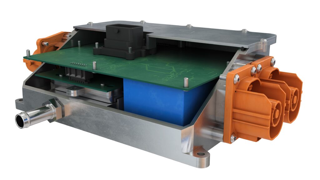
(Courtesy of Integral Powertrain)
Series production
For passenger vehicles set for volume production in 2022, the inverter design is still based around silicon IGBTs. The availability of IGBTs has a major influence on inverter design, the power of which ranges from 70 to 185 kW and has to support a typical lifetime of 100,000 km or 15 years.
One such design uses half-bridge modules, with a focus on the placement and orientation within the inverter to provide more thermal management to increase the power density. A key element is the substrate of the module, with a focus on cost and heat dissipation.
Half-bridge modules are aligned with the shape of the inverter on separate PCBs to meet customer requirements on space. There is also an EMI and EMC advantage in keeping the HV and LV components separated on these separate modules so that they interact less.
An expandable architecture for the inverter controller allows more features such as motor controllers to be added. The controller can also include advanced diagnostics to determine factors such as battery and bearing health.
In this design, tight integration of the inverter controller with the motor is a key approach for detecting leaks from the hydraulics or cooling circuits. Fittings and hoses minimise the potential for leaks.
Inverter designers are now looking at adding vehicle controller features such as the ECU into the inverter controller. Selecting a multi-core microprocessor and the higher level of processing power will allow for that capability in the future. As the inverter is already rated to the ISO 26262 ASIL D level of functional safety, these additional ECU functions can be added in a reliable and safe manner.
With the capacitors it’s all about the thermal management. Where the cooling scheme of the IGBT allows heatsinks on multiple sides, they can also be used for the capacitors. That allows the capacitor cooling to be tightly integrated with the IGBT by using the same cooling paths and surfaces.
The IGBT’s temperature is measured directly within the IGBT. This is one of the key areas to provide a fast response time to catch over-temperature and reduce the performance of the motor appropriately if the temperature of the inverter increases. This allows the inverter to handle higher temperatures than the standard 150 C of most modules.
There are several mechanical considerations for the design of the inverter, particularly with the cooling. The coolant circulates through the heatsinks around the IGBTs, the controller board and capacitors and then to cool the motor. The pressure drop throughout the coolant system is critical, so should be kept to a minimum.
Finite element analysis and modelling ensures the temperature of the coolant coming out the inverter is at the right level for the motor, and then there are considerations around how the vehicle dissipates the heat, but that is up to the OEM.
For a hybrid vehicle design, meeting the thermal goal is more difficult. That’s because the inverter sits in the engine compartment, and there are issues with the mounts, castings and isolation from the vibration. However, a lot of the components are shared across both full electric and hybrid vehicles, and so have to be designed to higher reliability requirements for the hybrid version.
The components have the same functional safety requirements in both types of vehicle but the safety requirements have to be addressed with different levels of integration with the motor. For example, for the hybrid the components need to be larger to meet the thermal requirements.
Power supply redundancy is built into the inverters, with secondary monitoring to diagnose faults. This is handled by external devices such as a smaller microcontroller or field-programmable device to monitor the microprocessor itself.
For mainstream vehicle designs, inverter designers are also looking at SiC in the future for higher power density. This move to SiC is driven by thermal management, particularly the cooling technologies. The multiple multi-side cooling can also be applied to SiCs to improve the power density above the current 35 kW/litre.
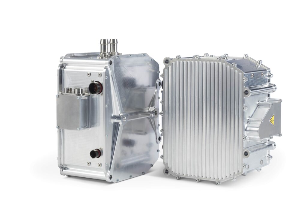
(Courtesy of Eaton)
Heavy-duty applications
There are different challenges for inverters in heavy-duty applications for trucks and buses. These are very cost-sensitive markets but also need high reliability.
The goal is to get the best overall performing vehicle-grade inverter. That means having the flexibility to customise the controller, provide long life, excellent EMC and fault protection, and superior motor control software.
One of the drivers for inverter designs is that continuous power levels are rising. Truck OEMs now want to replicate the performance of a diesel engine using an electric powertrain with no compromises, whereas in the past there has been an acceptance of lower performance.
This is leading to a new generation of inverter design that can provide the higher continuous power and still have sufficient headroom to deliver the peak power for acceleration, especially when moving a heavy payload. The peak power requirement also puts a significant strain on the IGBT power devices, which can reduce the lifetime of the inverter if not properly considered.
In these new inverters the phase current ratings are broken into three levels – maximum for worst-case events, peak for everyday peak events and continuous. Operating these inverters in the peak region and below will offer a life that is two to four times what an OEM typically requires.

The excess life can be consumed by the worst-case events such as pulling a full payload on a steep grade. That way the OEM doesn’t need to overdesign the system to meet the worst-case requirements.
An inverter targeted at package and delivery vehicles or off-roaders has a 360 V nominal, 425 V maximum DC input with 550 A rms of maximum phase current, 440 A rms of peak phase current and 300 A continuous.
For a full-size bus or a large offroad vehicle, the inverter has a650 V nominal, 800 V maximum DC input with 600 A rms of maximum phase current, 475 A rms of peak phase current and 300 A continuous. Combining two output stages in the inverter provides the extra peak torque that is needed to launch a large vehicle like an articulated bus.
The inverter has an efficiency of more than 98% with 230 A phase current and 10 kHz switching frequency. Even at 400 A and 10 kHz the efficiency is 97%.
That comes from good control of the gate and using an IGBT module that gives more current and lower losses. There are only two dies per switch in the module, and the large dies spreads out the energy, and so keeps the module cooler, which also helps efficiency.
The IGBT, DC link capacitors and internal construction have been designed for a high power cycle life over 2 million cycles at the rated peak current of 475 A rms. Drive cycle analysis for life consumption on a 500 A rms peak drive cycle shows a life of 200,000 h.
Part of this comes from the IGBT’s construction, where the coefficient of thermal expansion of the assembly is very well matched. This provides long life even when the junction temperature is high.
The design incorporates a full EMC filter on the DC input as well as common mode filtering on the output, achieving CSPR 25 class 3 on low and high voltage. Most of the frequencies meet the peak levels for classes 4 and 5.
Fault protection has been a key design element for a commercial inverter, as commercial vehicles need to be on the road for as many hours as possible.
The IGBT incorporates an on-die temperature sensor that allows instantaneous measurement of the actual die temperature. There is no thermal algorithm. The time constant of the die is 0.33 s.
During a torque step in a dynamometer test rig, the temperature of the dies rise to steady-state in a second, which allows the IGBT to be protected and shut down without damage, avoiding any reduction in the lifetime of the module.
This feature can also be used for dynamically estimating the lifetime consumption of the inverter.

Short-circuit protection means the inverter can withstand a phase short under any impedance condition. The current is monitored using a high-bandwidth sensor that allows continuous monitoring of the current during switch-on.
During a short, the condition is caught quickly before any damage can occur. This is different from the typical ‘desaturation’ method of monitoring for a fault, where the current isn’t monitored during switch-on and then checked after it should be on.
During a short in the motor winding the current can rise too fast, so the IGBT is in the process of failing by the time it is caught. That will damage the IGBT or take significant life out of it.
The design of the inverter is such that it can be put on its side and the coolant lines disconnected, so that all the coolant runs out while running at maximum current and the die temperature will not exceed 165 C inside the IGBT.
For future designs of larger commercial vehicles such as mining trucks, the next generation of inverter aims to double the power to provide over 1 MW of maximum power.
Controller flexibility
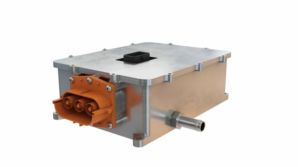
(Courtesy of Continental Engineering Services)
Previous versions of inverter used a depopulation scheme for the controller, where all the possible control combinations were designed onto a board and then certain parts left out.
However, there were always additional requirements or combinations of control elements from the OEMs, so this new generation uses a separate interface board. The board allows circuits to be added for additional features.
There is a high-speed bus to the controller board, so it will support a high level of functionality. A new version of the interface board can be developed and validated independently, so the main inverter controller isn’t modified; customising the inverter hardware therefore requires a simple revision of the interface board. That saves cost and time to market.
An example feature might be a backup power supply for the control voltage. If a motor has high back-EMF that would damage the system in the event of a loss of control power, a back-up supply can be added to keep the inverter alive for a short period and allow the inverter to reduce speed to a safe level of back-EMF before the inverter shuts down.
Another example is the ability to add cybersecurity to the CAN bus, as this always requires a hardware element to implement. A version of the processor for the target system can be added to the interface board to act as a translator for the inverter rather than having to redesign and re-certify the controller board.
Adaptive motor control
Adaptive motor control software developed for the inverter dynamically adjusts the motor to optimise performance. This provides more power and stability in the higher speed/ constant power region of the motor torque/speed curve and provides power gains of 15-38% in this region, depending on the motor.
Adaptive control also enables stable operation of a permanent magnet motor at up to 4.5 times the base speed. That means the vehicle can still hit top speed even at a low battery state of charge.
Mechanical considerations are also important with commercial vehicle designs. One inverter design uses connectors rather than lugs, as previous designs have shown it can be very difficult to know if a box using lugs is sealed.
That is because the O-rings on the covers can get pinched, and there is no way to test the seal to know that. With a leak test, air will leak through the wires going in and out of the box, and there is also the port that was used to apply a test pressure to the seal. Instead, high-voltage connectors can be used so that the seal doesn’t get disturbed by the connection process, and the seal of the unit can be confirmed at the factory.
The cable lengths are also a particular consideration for commercial vehicles, as the inverter might be installed on the roof of a bus, for example. While some inverters are limited to a cable length of 2 m, a cable length of 11 m is possible by using higher levels of shielding and higher current-handling capabilities.

(Courtesy of John Deere)
Future directions
The promise of SiCs is that the overall system will be smaller and cost less. Some of the cost-saving comes from lower system weight, but the high switching speed can also support higher pole-count motors. These can provide more torque, and with good, high-speed motor control can attain higher speeds without the need for a gearbox.
The higher voltages and faster switching also creates more electronic noise and more significant EMI issues. The high rate of change of voltage with time (dV/dt) also has the potential to set up a reflective wave, damaging the motor insulation system. Avoiding this means having the inverter integrated with the motor.
At this point the current SiC devices are not considered mature enough for larger commercial vehicles with higher power requirements. The package inductances are on the high side, which makes it difficult to cope with the higher dV/dt, and the die sizes are on the small side, meaning a lot of them would be needed in parallel to hit the 500-600 A rms levels. That makes fault handling an issue.
There are space and weight advantages with using smaller capacitors but these still have to handle the ripple currents. A segmented topology could be used to reduce the ripple current but that requires two interleaved power stages and a dual winding in the motor.
Having said all that, SiC will probably be used in the next-generation designs as the module technologies mature.
However, the IGBT is not dead.
A $74 million European project is aiming to develop the next generation of silicon IGBTs for inverters that can handle voltages over 1700 V and
temperatures over 200 C. This would enable a 20% increase in power density and increase the lifetime by 50%. It would also provide a 10% reduction in powertrain losses.
The project aims to manufacture these on ultra-thin, 300 mm wafers to reduce manufacturing costs.
(Courtesy of Curtiss-Wright)
Construction
At the highest end, construction equipment can use an inverter to drive large motors using the electricity from a generator rather than a battery pack.
For example, one 400 kW loader has the electric drive in two parts to allow for redundancy and scalability, with two generators providing power to spin the hydraulic pump and the generators. This decouples the engine speed from the vehicle speed and allows the designer to pick an optimum engine rpm by controlling the torque on the generator to provide the power.
In this architecture, the inverter is also part of a bidirectional regenerative link so that power can be recovered from the braking of the wheels and motors, and be used for the hydraulic system to lift the load.
Loaders are the first to use this approach, partly because of the work cycle, as there’s a lot of reversing, which means a lot of regenerative energy can be captured, as opposed to a bulldozer that is pushing dirt around all day.
That requires fast control, which needs to be able to change the torque quickly, coordinating between inverters quickly so that all the systems work well together. In the loader there is one 100 kW inverter per wheel with two generators, for a total of six.
These inverters operate at 700 V DC and many hundreds of amps. The equipment maker wanted the simplest transmission with the widest range, so it has only one gear ratio, and that choice decided the motor type and the choice of inverter.
Power is related to speed: high torque at low speed is not high power, so even though the inverter is working hard there are fewer losses, even though the power is wildly varying. The systems are all water-cooled, and that has a direct impact on the reliability of the system.
The equipment is caked with dirt, covered in debris, then power washed and submerged in water. That drives the need for a lot of ruggedisation and sealing as the temperature cycling from hot to cold, shock and vibration is a lot more extreme than in passenger designs.
There is also work on a dual 200 kW motor traction drive using SiC, but motor drives might not need the really high switching frequencies.
(Courtesy of CSM)
Testing
Even small improvements in efficiency visibly increase the later range of a vehicle, but getting an exact measurement of that efficiency can be challenging.
To avoid long sensor cables and associated EMC interference, measurements should be taken as close as possible to the sensor using sensor modules. In high-voltage areas, the measuring system must be designed to be high-voltage-safe from the sensor via the measuring cable to the measuring module.
A direct, phase-accurate measurement of currents and voltages in a high-voltage vehicle’s electrical system is required in order to be able to calculate power precisely.
The use of the same measurement technology in test benches and mobile vehicle testing is desirable, and enables clear comparability of the measured values.
Simultaneous acquisition of measured variables from vehicle control units via a plug-on device and the measuring system is also desirable, in order to be able to correlate measurement results.
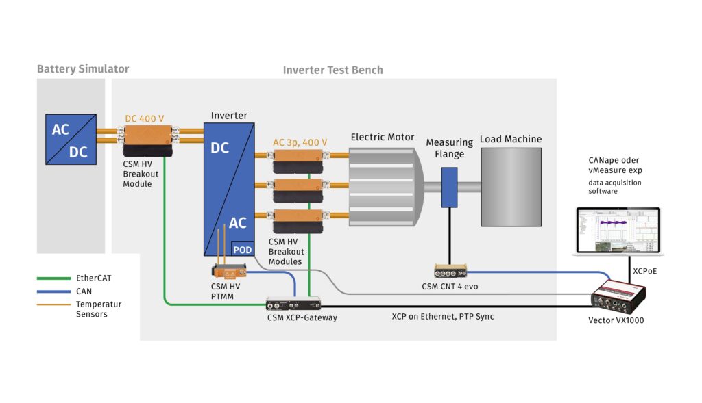
Inverter test benches require special access to the (usually) three-phase AC high-voltage cables in order to be able to measure between the inverter’s output and the associated electric motor. In dedicated inverter test bench solutions, the electric motor is simulated by a load emulator. A new and simpler approach to power measurement is direct measurement in high-voltage lines on test benches.
Modules are used to measure currents via a shunt and voltages simultaneously, and with phase accuracy directly in the high-voltage cables. The module can be used with a power analyser to measure the current and voltage samples to calculate the power in real-time. That allows multi-channel analysis of power and simple calculation of efficiencies.
The image above shows a set-up for measuring an inverter efficiency on a test bench. In addition to DC power measurement, the system is extended by using HV breakout modules in each of the three AC phases.
The three high-voltage modules in the AC phases are connected to each other for power measurement via a three-phase, three-wire system. The three AC phase currents and the three triangular voltages are then measured.
The analyser performs the delta calculation to convert the delta voltages into the star voltages and the power analyses. The inverter’s efficiency is displayed as the division between the three-phase AC active power and the DC input active line.
For control purposes, the temperatures in the inverter are also measured. This is necessary because inverter operating points are usually approached quickly in order to determine the efficiency at a fixed temperature.
Acknowledgements
The author would like to thank Arnaud Martin of Integral Powertrain, Ron Joyce of Curtiss-Wright, Kent Wanner of John Deere, Matt Nolan and Vasilios Tsourapas at Eaton, and Florian Twardowski at CSM for their help with researching this article.
Some suppliers of inverters
Austria
Canada
Germany
UK
USA
ONLINE PARTNERS
