


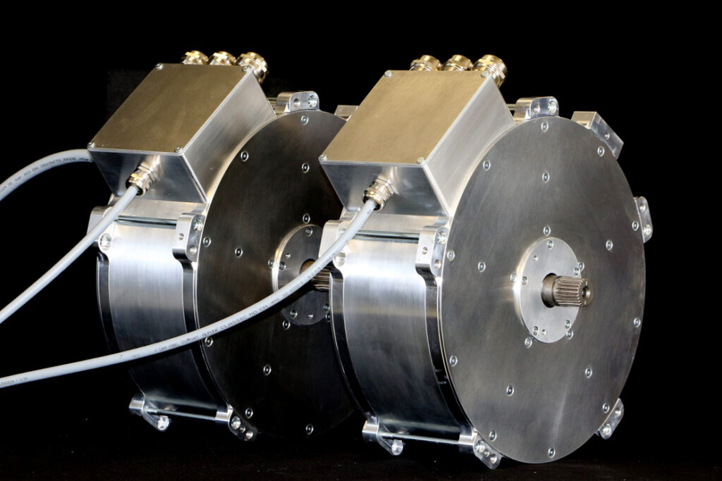
Phi-Power PHI301 axial flux motor
Performance art
Lawrence Butcher investigates the technology and engineering behind this compact but powerful motor design.
Something of the new kid on the block in the world of electric machines is the axial flux motor. It is a topology which in recent years has seen increased adoption in many e-mobility applications, with the arrival of a number of companies producing motors that fulfil both traction and auxiliary drive functions.
Axial flux machines are by no means a new invention, in fact some of the first electric motor designs were axial flux units, but for various reasons they failed to see widespread adoption in the same way as radial flux machines. One of the main stumbling blocks for axial flux machines has been the high cost of producing the rotor and stator components, but developments in manufacturing technology have gone a long way to negating that.
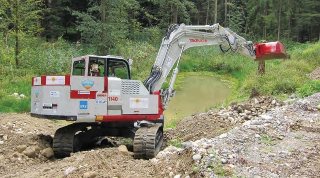
One proponent of axial flux technology is Dr Michael Lamperth, founder of Swiss company Phi-Power, which produces a range of axial flux motors that have seen use in vehicles ranging from off-highway earth-movers to motorcycles. The PHI301 motor shown on these pages was developed to be suitable for a wide range of applications and is in fact used in the Johnston Sweepers EVIE street sweeper detailed on page 48.
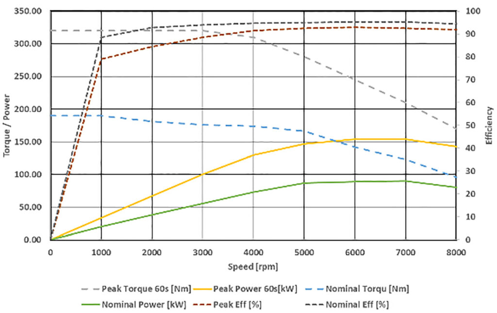
The PHI301 is a central-rotor, surface-mounted, permanent magnet, axial flux machine, and is one of a family of Phi-Power motors that share this topology. It has a maximum operating speed of 9000 rpm, with a power output of 160 kW (nominal 85 kW) and a torque output of 520 Nm/384 lb-ft (nominal 190 Nm), for a package weight of 29 kg.
Lamperth notes that there are subvariations of the basic motor design available, which are tailored to different applications. “We use this motor in automotive, UAV, motorbike and hybrid vehicle systems,” he says. “Sometimes, adaptation will simply involve producing a different housing for a new application; other times, such as with a hybrid system, we use the PHI301 rotor with a different stator.”
That fundamental flexibility is important because it allows customer applications to be catered for without having to develop new designs from scratch. “It keeps lead times down and helps control costs if you can work from a selection of standard parts,” says Lamperth.
Architecture
Being a central-rotor axial flux machine, the PHI301 has two stators, which sandwich the rotor, the stators being indirectly cooled. Unlike in a radial flux machine, where the stator consists (in most cases) of a stack of electrical steel laminates, Lamperth says the stator in an axial flux machine – while still made from laminates – takes a different form.
“It is a spiral. You use the same material [as a radial flux machine] but the manufacturing process is very different,” he says. “You take a band of steel and wind it up, while simultaneously stamping the slots.”
Although complex, the technology for mass producing axial flux stators is becoming more widely available. However, Lamperth points out that the key to obtaining high performance is ensuring accurate alignment of the slots in each laminate layer.
An uneven surface along a slot will reduce the efficiency of heat transfer from the stator core to the windings. As the laminate layers are formed into a spiral to create a core, too great a tolerance in the dimensions of each discrete slot in a layer will lead to a ‘wavy’ surface. Phi-Power has worked with a partner to develop a proprietary process to increase accuracy in its cores, but Lamperth was understandably reticent to divulge too many details.
He emphasises that selecting the stator material is very important for performance, both regarding the type of material and the thickness of the laminates used. “It depends on what you want to achieve, as to whether you use steel or other materials such as cobalt iron. For example, in our Formula E motors we used a cobalt iron,” he says.
“The role of the material is to allow the magnetic flux to flow, and the [magnetic] saturation point of cobalt iron is higher than electrical steels. So with a material like that, you can reduce losses and increase torque at the same time.”
In the case of the PHI301, standard electric steel is used for the stator, the laminate thickness varying according to the specific application. “We go from an NO10 thickness steel [0.10 mm] up to an M330 [0.35 mm] depending on the application,” Lamperth says. “They all have different losses, and the thinner you get [with the laminations] the lower the losses, but thinner also means harder and more expensive to manufacture.”
He points out that although there is performance to be gained from thinner laminates, in the wrong application these benefits may not be realised. “If you have a motor that only runs at 3000 rpm, you would select a much thicker steel, because the slow speed means the switching frequency is low, so the losses are also lower. Going for an expensive, thin laminate in that instance is a waste of money,” he says.
The PHI301 uses standard, round copper wire for the windings, and a distributed winding pattern, although Lamperth notes that there is the option to use a fractional slot-type winding if needed. He says there are considerable benefits to using a distributed winding. “It allows for a good winding density and good contact between the windings, which is beneficial for heat transfer.”
Stator cooling
Next to the active element of each stator is an aluminium cooling plate, which is in direct contact with the stator windings. The plate incorporates internal cooling channels, with the favoured cooling medium being water (or a water-glycol mix in most applications).
Lamperth says coolant choice is often driven by customer demand. “They might ask for oil cooling, so we can accommodate that – even though it is less effective. We can also use distilled water, which if you know the application will not see freezing conditions can be very effective.”
Phi-Power has also produced variants of the motor where the liquid cooling is replaced with a system to allow air cooling. “We have also done applications where we have just used an aluminium heat sink that mounts directly to the chassis of the vehicle,” says Lamperth.
While the coolant flow paths through the cold plate are subject to a degree of optimisation, to improve heat transfer to the cooling medium, Lamperth says the most important element to consider is the interface between the stator and the cold plate. Maximising the thermal conductivity in this area is what produces efficient cooling.
“Our focus is on the heat flow from the windings to the cold plate – for example if the contact between the windings and the plate is poor, or the cooling efficiency between the windings and the stator core is reduced,” he says. “Elements like the surface flatness of both the core and the cooling plates have a far greater impact on cooling than the coolant flow within the cold plate. Getting heat into the coolant from the plate is easy, it is getting heat into the plate that is the challenge.”
The insulation material that encases the stator windings also plays an important role in cooling efficiency. In the case of the PHI301, an insulating varnish is used on the stator windings. Lamperth was unwilling to divulge the precise specification of varnish used, but he was happy to explain the requirements the varnish has to meet.
“There are varnishes available now that have a much better heat transfer capability than in the past,” he says. “You can get single-, double- or triplecoated wires. With a single coat, you get pinholes in the coating, and using a double coating fills in those pinholes. But even with a double coating, there may still be some holes, so you can triple-coat.
“This need to fill pinholes [and the reduction these holes cause in the insulating properties of the varnish] is related to resistance to corona discharge [the ionisation of air surrounding a high-voltage wire, which can damage the insulation]. A triple-coated wire should be resistant to corona.”
However, with a triple-coated wire the coating is relatively thick, which reduces the efficiency of the heat transfer out of the windings. “If you use a single-coated wire, you get good thermal performance but you will have a problem with the corona effect, which will destroy your machine.
“So the trick is to find a pinhole-free, corona-resistant wire that has a thin coat. They do exist, and we are able to use them,” Lamperth says.
He also points out that the thicker the insulating layer used to protect the windings, the less space there is for copper, so the resistance of the windings rises for a given current, leading to greater electrical losses. “It is a vicious circle,” he says.
On that last point, the copper fill factor of the stator in the PHI301 is around 60%, but Lamperth makes the interesting observation that sometimes, having the maximum possible fill factor is not always best for overall motor performance.
“You might have a lower fill factor but have a stator that is very good at transferring heat, so it can be more efficient overall,” he says. “Also, in an air-cooled motor for example, you might not want the end windings to be compacted together, in order to maximise the surface area of winding exposed to the air.”
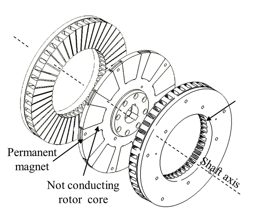
Rotor construction
With a permanent magnet axial flux machine, the magnetic material is arranged around the exterior of the rotor. The magnets in the PHI301 are wedgeshaped, with a blunt distal end, and are secured in a spider (or yoke) that attaches to the motor output shaft. Much
as with the design of the stator, the rotor’s layout is tailored to maximising the electrical performance of the motor while also providing sufficient structural integrity at high speeds.
“The same issues with losses that apply to stator materials also affect the magnets. You have eddy currents from harmonics in the magnets, because they are still made from a conductive material. To help increase efficiency from a high-speed, high-frequency machine [such as the PHI301] you need to use laminated magnets,” says Lamperth.
The reason for that, he says, is because “the losses in the magnets are reduced by the square of the number of laminates you use. So if you slice one magnet in half you reduce the losses by more than half. The thinner the laminates, the lower the losses.” The individual magnet laminates are glued together, the glue also acting to isolate each laminate electrically from the next.
However, there is always a compromise to be struck. “Moving from a single piece of magnetic material to a laminate made of four pieces has a huge impact on losses. But the move from four to six is much less effective and is more expensive, so it is a process of diminishing returns,” he says.
One also has to consider that every glued joint reduces the amount of magnet material present for a given volume in the rotor, Lamperth pointing out, “If you go too thin with the laminates, you can end up with 50% magnet and 50% glue.”
The PHI301 uses neodymium magnets in the rotor. “Depending on the exact application, we will use up to an N38 (high-temperature variety) material or higher, which is dictated by the motor’s operating temperature,” says Lamperth.
In the case of the PHI301, the rotor temperature will sit at 100-120 C, but “from a design perspective, we will make sure the motor is safe up to 200 C,” says Lamperth. “Under peak power conditions, the rotor can reach 165-170 C. That’s why we need to make sure none of the parts [be they the magnets or the spider material] will be adversely affected.”
The spider that the magnets are mounted in is produced from a high temperature, non-conductive composite. Lamperth says it can be made from carbon fibre composite, but that is not the case with the PHI301, and he was unwilling to specify the exact material used.
The spider is non-magnetic so as to reduce electrical losses, which would be present if, for example, steel was used. It also has to be sufficiently strong to resist the high torque it is subjected to, as it is effectively the power take-off point from the motor.
The magnets are secured in the spider using a retaining ring, which runs around the periphery of the rotor. The detail design of the mechanical interface between the magnets and the spider is of utmost importance as far as the structural integrity of the whole assembly is concerned.
Lamperth says, “If the magnets, or the holes in the spider, are not kept to tight tolerances, the magnets can be pushed unevenly into the spider at high speed. That means you end up with stress concentrations.
“The interface between spider, magnet and retaining ring is a crucial area of the design.”
Phi-Power assesses the dynamic interaction of these components using FEA and physical tests (spinning the rotor up to beyond normal operating speed). “We have test stands to ensure that we know how the rotor will behave. For example, we need to make sure the composite material that makes up the spider will not lose its mechanical properties when running at the motor’s operating temperature and speed,” he says.
The rates of thermal expansion for the spider, magnet and rotor also has to be accounted for in the design of the rotor. “You need to minimise potential issues with thermally induced stress concentrations. All the parts have different expansion rates, and you do not want that to add additional stress to the assembly,” Lamperth says.
“For example, if the spider was to expand more than the magnets and retaining ring, it would create a very sharp edge between the magnet and the spider. That would lead to a high stress concentration and potentially facilitate a failure.”
On the subject of magnet retention, axial flux machines have a useful advantage over surface-mounted, permanent magnet radial flux units. On a radial flux machine, the magnet retention system impinges on the air gap between the rotor and stator, meaning the thickness of any retention system used needs to be minimised in order to keep the air gap as narrow as possible.
On an axial flux machine, the magnets are retained around the circumference of the rotor, so the retaining system does not intrude into the air gap. That means the retention system used can be more substantial (within reason) without impacting on the performance of the motor, allowing for a greater safety factor to be incorporated.
The design of the rotor, coupled with the motor casing, also has an important effect on windage losses, which can, says Lamperth, be a significant issue at higher operating speeds.
“The advantage of an axial flux motor is the relationship between torque and diameter [the greater the diameter, the higher the torque]. That though has a sting in the tail at high speed – the faster you go, the more the benefit of the axial flux machine becomes a disadvantage,” he says.
Put simply, the large diameter of the spinning rotor leads to higher windage losses, greatly reducing motor efficiency.
“With an axial flux motor, if you run it continuously at high speed, windage within the machine can lead to high temperatures, increasing losses, both mechanical and electrical,” Lamperth emphasises. Thus, axial flux motors are best suited for applications where high torque output (at lower speeds) is the priority over power (which is a function of rpm).
Because of the space constraints within a motor, the scope for reducing windage losses through design are limited. “There are some refinements you can make with the inside geometry of the casing to help smooth the airflow. You can also refine the centre of the rotor design to help evacuate the air from the motor. But there are limits to what you can do,” explains Lamperth.
Containment
One potential issue with axial flux machines compared to radial flux motors is the potential for external damage in the event of a structural failure of the rotor.
In a radial flux motor, the rotor is effectively restricted by the stator, which acts as a containment device. With an axial flux unit, failure of the rotor would see the pieces flung outwards between the two stators. Thus the housing the stator and motor are mounted in also needs to act as a containment system.
Lamperth says, “The material we use for the housing needs to have the right balance between strength and high thermal conductivity. It must have a good capacity for elongation under impact if the rotor was to fail.”
He notes that rotor failure should not be a problem, given that the magnet retention system around the periphery of the rotor is built with a high safety factor, but a worst-case scenario still needs to be accounted for.
Even if the rotor were to fail, the containment provided by the outer casing should be the last line of defence.
As Lamperth explains, “We have engineered it such that in the event of a failure, the rotor will rub against the casing rather than fly into it in pieces. That means the housing should not be subject to sudden impact from parts.”
In the case of the PHI301, the casing is machined from aluminium, which Lamperth says gives the right balance between ductility and strength. PhiPower has also built motors where the outer containment ring – the section of the casing that runs around the periphery of the rotor – is made from a combination of carbon fibre composite and aluminium.
“With that design, we wrapped the aluminium containment ring in carbon fibre,” he says. “The aluminium provides an energy-absorbing layer while the carbon fibre adds strength and stiffness to the structure.
“Carbon fibre alone would not be feasible, as it couldn’t withstand a sharp impact in the event of a rotor failure. When used with aluminium though, you get the strength without the weight of an all-aluminium structure,” says Lamperth.
Beyond containing the rotor in a failure scenario, the casing design is important from a stiffness perspective. It must be strong enough to ensure the dimensional stability of the internal components – the less deflection there is in the rotor and shaft, the tighter the air gap can be kept – while also providing good installation stiffness in a vehicle.
On that second point, an axial flux motor is an inherently stiff design, thanks to its short length and large diameter.
“This is one of our strong points: you have very good torsional stiffness because of the motor’s form and also the reinforcement afforded by parts such as the cooling plates on each end,” says Lamperth.
Ultimately, the balance between stiffness and weight – with the requirements that places on material selection and detail topological optimisation of the casing – is dictated by a customer’s specific needs.
“An important factor to remember is that it is not always about building the motor with the highest torque-toweight ratio,” Lamperth says. “In most applications, the primary concern is building a motor that fits in a given space envelope and that will provide reliable service.
“Taking the motors in the Johnston street sweeper, the company is more interested in the size of the package than an extra kilo of weight. So it is better to be conservative when it comes to ensuring structural integrity.”
Versatility
The Phi-Power motors are designed to operate with a wide range of offthe-shelf power electronics, to make matching a motor to a customer’s installation straightforward. “We prefer to run the motors with field-oriented control,” says Lamperth.
This is a variable-frequency drive control method, in which the stator currents of a three-phase AC electric motor are identified as two orthogonal components that can be visualised with a vector. One component defines the magnetic flux of the motor, the other the torque.
Many commonly available inverters offer this type of control, and Lamperth says Phi-Power’s motors do not need exceptionally high switching frequencies. “Higher frequencies are better [for efficiency] but we tend to operate the motors at between 8 and 12 kHz. Again, there are many inverters that can operate in that range,” he says.
With an eye towards costeffectiveness as well as easy integration, positional measurement of the rotor is achieved via a resolver mounted on the output shaft.
Different resolver types can be used depending on application, but for most, Lamperth says, “We use industrial-type resolvers that are common and easy to buy. Generally they will be reluctance-based resolvers, and again, most inverters can interface with these.”
Overall, motors such as the PHI301 and other axial flux designs offer EV manufacturers an excellent balance between performance and compact package size, particularly in applications where lower-speed torque output is a priority over outright power.
With the ability to stack motors and thus easily increase performance, they are finding particular favour in hybrid applications – their short length allowing them to be easily packaged between engine and gearbox – as well as heavy and off-highway vehicles, where maximum torque output for a given size is the name of the game.
For example, Phi-Power is working on a family of large motors with an output in the 4000 Nm range. It is therefore likely that in some areas, axial flux technology will see increased adoption where its benefits can be fully realised.
Some key suppliers
Magnetic materials: Bakker Magnetics
Casing (material supplier or manufacturer): Kreier Mechanik
Shafts: Grob AG Nebikon
Bearings: SKF
Insulation materials: Dupont
Cables: Huber & Suhner
Connectors: Amphenol
Simulation and design software: Ansys
Test systems (dynamometers and so on): Datum Electronics
Description of axial flux machines
Axial flux motors are available in various configurations, with the unifying characteristic that the magnetic flux passes axially through the air gap between rotor and stator. The axial flux topology is not limited to just permanent magnet machines – induction and brushless DC designs are available as well – but, by and large, permanent magnet machines are the favoured option for most applications.
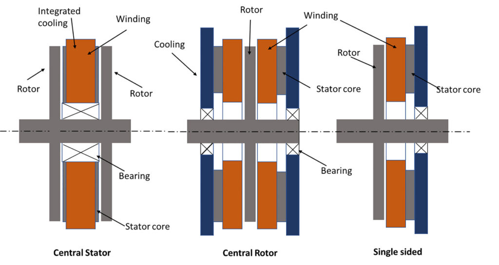
Axial flux motors can be categorised into three main groups – single-sided, central rotor or central stator, which describes the arrangement of the main elements of the motor. These layouts are shown in the illustration above.
Single-sided machines tend not to be used, as their layout, with the rotor offset to one side of the stator, creates an imbalance. The rotor will therefore try to tilt along the axis of rotation
Motors such as those produced by YASA use a central stator set-up, with a rotor assembly either side of the stator. Direct cooling of the stator is often necessary with this type of design, as there is only a small surface area available for indirect cooling.
Central-rotor machines could be viewed as two single-sided machines sandwiched together. From a packaging perspective they are not quite as compact as central-stator machines. Challenges such as cooling the stator are considerably smaller, not least because the use of two stator elements (one on each side of the rotor) gives a large surface area to cool.
Vehicle installation can also be more straightforward, as the rotating components are internal to the stators, making mounting the assembly easier.
Anatomy of the Phi-Power PHI301
Motor designation/model number: PHI301
Motor type: axial flux permanent magnet, internal rotor with double stator
Operating voltage: 250-800 V (depending on winding configuration)
Power output: maximum/rated, 160/85 kW
Motor weight: 29 kg
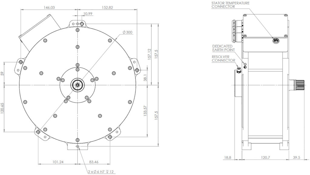
Length: 120 mm
Diameter: 300 mm
Number of phases: three
Number of poles: 10
Casing material: aluminium
Stator material: NO20 steel
Winding type: distributed
Cooling: indirect (water)
Power electronics: silicon IGBT
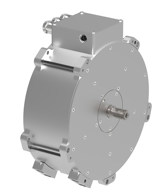
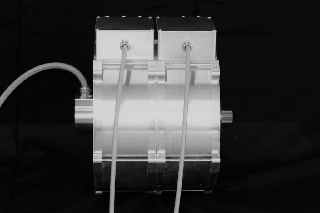
The PHI301 is a central-rotor, surface permanent magnet, axial flux machine. A machined aluminium housing encases the active elements of the motor, which are arranged with the rotor sandwiched between two stators. The housing is constructed from aluminium alloy, which acts as a structural support for the internals while also providing ballistic containment of the rotor in the event of a failure.
The casing is made up of three main sections – an outer containment ring, which has a 6 mm wall thickness and runs around its periphery; and two side plates, to which the stator elements are attached. These end plates also incorporate cooling channels for the stator elements. The two end caps are secured by cross-bolts that run across the containment ring.
Connectors for the high-voltage cables and cooling system are located in a box that sits on the upper side of the motor casing. In the centre of the casing, parallel to the output shaft, is a housing containing a resolver to determine rotor position.
The rotor is formed of a non-metallic composite spider, which is directly connected to the perimeter of the output driveshaft. The shaft is supported on ball or angular contact bearings depending on the application.
The form of the output drive shaft is also application specific. A splined shaft can extend from one or both sides of the motor, or where multiple units are stacked, a male and female spline allow easy interlocking.
ONLINE PARTNERS

