


Power and torque density
(Courtesy of Rolls-Royce)
How do you choose the most suitable type of motor for a given application? Peter Donaldson gets some expert input.
Motor motives
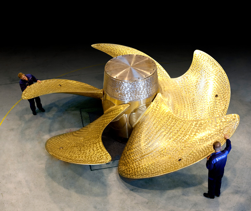
One of the many challenges facing the developers of the BB Green ferry project was finding an electric propulsion motor of sufficient power, power-to-weight ratio, compactness and durability for the battery-powered vessel. The purpose of this article is to explore the challenges inherent in developing motors to meet this kind of requirement. Although not involved in that project, we asked PhiPower’s CEO Dr Michael Lamperth, Integral Powertrain’s CTO Andrew Cross and Avid Technology’s MD Ryan Maughan for their views on the issue.
To drive the 28 t BB Green at 35 knots, Echandia calculated, requires 620 kW, a figure reached with power to spare by a pair of axial flux permanent magnet motors rated at 330 kW continuous power each at 2600 rpm. These motors weigh 210 kg each and are 620 mm in diameter by 230 mm long, increasing to 275 mm when a position sensor is included.

The choice of an axial flux motor was driven by the greater torque density available from this topology compared with the radial flux motors used in the ferry’s prototype, the AirEl, which resulted in an installed weight saving of more than 660 kg. The other metrics they used for comparison with radial flux motors were cost, overall efficiency, torque ripple and manufacturability.
In all of these bar overall efficiency, radial flux motors equalled their axial flux counterparts or bettered them by a small margin, but the margin in torque density in the axial flux motor’s favour was large enough to sway the decision. However, in their 2019 product development report, the team stated their intention to invest further engineering efforts to secure more weight (and cost) reductions in the motors, gears and mountings.
A 330 kW motor that weighs 210 kg has a power-to-weight ratio of 1.57 kW/kg, and state-of-the-art electrical machines exceed that by an order of magnitude or so, although they are not necessarily marine-certified. Before getting into what some of the best-performing motors on the market can achieve in terms of power-toweight ratio, it is worth recalling that power is a function of torque and rotational speed, so low-speed motors tend to have relatively low power-toweight ratios, which is why torque density is sometimes seen as a more useful comparator.
Achievable power and torque densities
“Essentially, what defines the motor is not the power but the torque,” PhiPower’s Lamperth says. “In order to achieve torque you have to have force, and that force is created by the electromagnetic interaction, which you can imagine as a tension between the rotor and the stator expressed in newtons per square millimetre. For torque in newton-metres you multiply by the radius, and for more newtons you need more square millimetres, so the motor has to be made bigger.”
Our experts concur that powerto-weight ratios of 15-30 kW/kg are readily achievable, depending on the speed and duty cycle appropriate to the application and with caveats about gearing. For example, Lamperth says that 4 kg machines he has built generated 60-70 kW at 60,000 rpm but emphasised that this would be unsuitable for a car as the reduction would require a heavy and complicated transmission.
Integral Powertrain’s Cross says, “We’ve tested and deployed in a few applications now with over 20 kW/kg continuous power density, and a peak power density of more than 30 kW/kg.”
Illustrating the effect of rotational speed on power density, Avid’s Maughan says his company has achieved 10 kW/kg on machines running at 10,000-12,000 rpm.
Even with the same level of technology, a direct-drive motor would have to be bigger and heavier for a lowspeed application, he says. “One that gives you 500 kW at 2000 rpm looks completely different from one that gives you 500 kW at 10,000 rpm, because you need so much more torque at low speed. More torque needs more current and magnets, so it’s therefore a larger motor.”
Fundamental limits
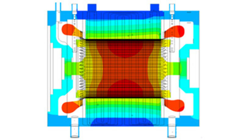
Thermal management is one of the biggest challenges in the quest for greater torque density in electrical machines, and as they get smaller and more powerful, liquid-cooling becomes more attractive
(Courtesy of Lucid via Ansys)
Fundamental and practical limits to motor performance in terms of power and torque densities stem from the physics of the available motor topologies, induced losses and inverter switching frequencies.
At the level of basic physics, the limits of performance are set by the above-mentioned tension, also known as air gap shear stress, which is related to the strength of the magnetic force transmitted between the rotor and the stator, and the area over which that forces acts to create the torque, multiplied by the rotational speed to get the power.
In a radial flux motor, the air gap is shaped like an open-ended cylinder, while in an axial flux motor it is like a disc with a hole in the centre.
Induced losses can be broadly divided into DC losses and AC or eddy-current losses, and both generate waste heat that has to be managed. The DC losses are associated with the current required to make the torque, and are caused by resistance in the copper windings in the motor, which can be minimised with copper alloy selection, increased cross-sectional area of the conductors and cooling. Eddy currents are induced by the core rotating in a magnetic field.
Both sap energy that designers would prefer to be available to generate torque. Increasing the electrical resistance of the core is an effective way of reducing eddy currents, and this is done by constructing rotor and stator cores from thin layers of iron separated by insulating layers, reducing the crosssectional area of the conducting layers.

Motor cores also suffer hysteresis losses from reversals in the magnetic field in the core material, which limits the magnetic flux density – expressed in Tesla (T) – that available steels can support. The use of cobalt-iron can increase magnetic flux density by 25% or more from 1.7 to 2.2 or even beyond 2.3 T, Lamperth says. “And that means a sizeable increase in the torque you can generate.”
All the induced losses turn to heat, and the higher the torque density you try to get, the more heat you will generate in a small volume, Maughan points out. “Thermal management inside the motor is the key challenge, while electrical and electromagnetic optimisation are key in terms of getting the best out of it.”
Few inverters are capable of switching at frequencies of more than 1000 Hz in high-power applications, which is another limitation. The need for high-power, high-frequency inverters is driven by engineers’ desire to build motors with larger numbers of magnetic poles in pursuit of more torque.

The switching frequency required by a motor is a factor both of its rotational speed and the number of poles, and a motor with a lot of poles will generate a correspondingly large number of electromagnetic interactions for every revolution. Therefore, even a slowturning motor will run at a very high switching frequency that might be beyond the capability of available highpower inverters, forcing the designer to bring the pole number down. That makes the motor bigger again, so finding the optimum is essential.
Lamperth points out, however, that the higher switching frequencies available from silicon carbide inverters can have a large and positive impact here. “When you go to those, the motor has a much easier life.”
Dealing effectively with highfrequency induced losses in motor cores is demanding but potentially very rewarding, Cross notes. “There’s a lot of detailed physics in there, which is really very amusing from an engineering perspective, and it is something we’ve invested a lot in over the past decade or so,” he says.
“I think we can see our way to 50 kW/kg with the current practical applications.”
Axial flux versus radial flux
It is well-known that axial flux motors provide better torque at low speeds, while radial flux machines generate more power at high speeds. Much of that is due to geometry, Lamperth says. “The geometry helps you because you get a cubic increase in torque for an increase in diameter, but with a radial flux machine you get only a square increase in torque,” he says.
He adds that small, high-speed radial flux machines are becoming very powerful, “but you get a bigger bang for your buck if you go larger with an axial flux machine”.
Maughan adds that, thanks to its geometry, an axial flux motor also has a higher magnetic surface area available to do work in the air gap than a radial flux motor of equivalent volume. He also points out that axial flux motors have proportionally more surface area for the cooling jacket, because their pancake shape has a larger ratio of surface area to volume.

In light of these advantages it might be considered desirable to spin an axial flux motor faster to compete with the radial flux motor’s power density, but there are inherent electromagnetic and mechanical problems with this.
Maughan notes that the more torque a motor has at low speed the harder it is to make it spin fast. “You’ve got these very strong magnetic fields that create back-EMF voltage, which you then have to manage through fieldweakening,” he says.
Field-weakening involves injecting current at 180º to the live phase to reduce the effective magnetic field in the air gap, which is wasteful of energy.
This is less of a problem in radial flux motors because they can be built as hybrid permanent magnet and reluctance machines, enabling control of the magnetic flux in the motor using reluctance effects. “That means you can basically turn portions of the rotor magnetic field on and off, so at high speeds you can control the back-EMF without having to use very strong fieldweakening,” Maughan says.
The topology of an axial flux machine, however, makes such a solution much harder. Maughan says it is quite complicated to control, because the software has to manage both the primary current flow in the stator and the secondary field-weakening or reluctance effects. It is however probably the most common type of motor used for traction drive in EVs, because of the high level of control over magnetic field strength in the rotor.
While very useful in a car, he adds, this kind of solution would probably not be needed on a ship with a propeller turning at a constant and fairly low speed most of the time. Knowing the resistance of the water means that the torque required to keep the propeller at the selected speed is also known, even if it is occasionally affected by changes in water conditions.
Cross notes a different issue that limits the speed of axial flux machines that is more mechanical in nature, one that centres on maintaining the stability of the air gap to ensure that the rotor and stator never touch. This is relatively straightforward in a radial flux machine, whose air gap is between two concentric cylinders and all the forces are balanced.
“It gets more difficult though with an axial flux motor, where the forces aren’t balanced with the rotor,” he says.
An axial flux machine designed for high speeds might need much larger diameter bearings in the centre or some means of controlling the outer edge, or both. A typical axial flux machine from Integral Powertrain would have an air gap of less than 1 mm, so it wouldn’t take much angular wobble at the centre of a large-diameter motor to get more than enough movement to create contact at the edge.
While permanent magnet alternating current (PMAC) motors generally have higher power-to-weight ratios and torque densities than equivalent induction machines, careful design and a focus on reducing the losses in the rotor can reduce the difference in performance between the two types. This makes induction motors an attractive option in applications that can accept a little more volume and weight, even where performance is at a premium.
Rotors in induction machines are referred to as squirrel cages, because of the shape formed by the bars that carry the current through them. Lamperth explains that changing the material of the cage’s current-carrying elements from aluminium to copper is the key to reducing losses and heat build-up, and achieving comparable performance to PMAC machines, particularly in high-speed radial motors, as used by car maker Tesla.
What’s more, induction machines do not use any permanent magnets, which makes them immune to the cost and supply fluctuations affecting rare earth magnet materials.
Maughan argues that with current scale manufacturing methods and materials, a PMAC motor should still be better from a power density and torque density point of view than an induction motor.
The relative performance potential of PMAC and induction machines was the subject of debate between Maughan and an academic who, in response to a white paper Maughan published, argued that it is possible to build highspeed induction motors (50,000 rpm) with very high power-to-weight ratios (but relatively low torque density). His reasoning was that because the rotor magnetic field can be controlled in an induction machine it can be very efficient at such high speeds compared with a PMAC motor, which will need field-weakening.
“Typically, a high-speed PM motor is a surface magnet machine and has almost no reluctance torque,” Maughan says. “But if you design it right you would make it need more fieldweakening at the target speed.
“We discussed the comparison. I did some quick calculations and showed that using our kind of motor we could make a more power-dense PM machine – either in surface magnet form with no reluctance or interior permanent magnet form with reluctance – than an equivalent induction machine, even with a highly optimised and cooled rotor.”
(Courtesy of Avid Technology)
Application limitations
Real-world applications place a variety of limitations on motors that militate against ultimate performance in terms of power-to-weight ratio and torque density, including the space and cooling capacity available. Perhaps the most dominant feature of the kind of application discussed here is propeller shaft speed, Cross argues. “It’s really a combination of the shaft speed, the power level required and any package limitations,” he says.
“To achieve the same power density, we can swap rpm with radius, so you can have, for example, twice the diameter running at half the speed, and the air gap velocity is the same and power density can be the same. But what happens as you go for a given power level at a lower shaft speed and a larger diameter is that the motor starts to tail off owing to geometrical end-effects.”
These end-effects, he explains, stem from parts of the motor that don’t contribute to torque but become proportionally larger with diameter.
“What is doing the useful work in the motor is those magnets in the rotor interacting with the stator teeth, which are energised by the copper coils. However, the ends of the copper coils, the bearings, the ends of the rotor, the ends of the motor, they don’t contribute to torque,” he says.
“For example, if you try to make a 100 kW motor run at 1000 rpm it will probably have a 5 mm stack length and have 20-25 mm end-windings, so most of their weight would be wasted. That is a practical limitation, and one that is perhaps not that obvious at first.”

Another is noise, vibration and harshness, which is clearly important in passenger cars but not so obviously in a fast ferry designed for short journeys. There are, however, marine applications in which this is crucial, as in vessels that deploy acoustic sensors to survey or monitor the environment.
While electric motors are smoother and quieter than ICEs they can produce torque ripple, which is a source of noise and vibration, and engineering efforts to minimise it generally reduce performance. “A motor with low torque ripple will have lower overall torque,” Lamperth points out.
Explaining this, he draws a comparison with efforts to reduce noise generated by gears. Straight-cut spur gears, for example, transmit torque very efficiently but are noisy. A common solution is to cut the gear teeth into a helical form that smooths the contact between them, but that also generates axial thrust loads that wastefully absorb energy, limiting the torque they can transmit.
This applies directly to electrical machines, and in radial flux motors for example, the magnets can be arranged in a helical curve to smooth out torque ripple. Magnet shaping can also be used for the same purpose in axial flux machines, and windings can be slanted. All work by cancelling out some of the torque.
These geometric solutions to torque ripple all reduce performance, but there is an alternative, Lamperth explains. “You can introduce more phases – go from three to six for example,” he says. “That’s a way of getting the best of both worlds: you will have less ripple torque because of the larger number of phases, but you also get more power out.”
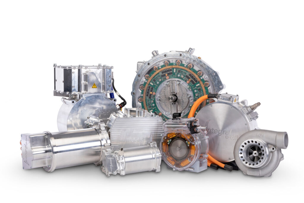
In recent years, Maughan notes, the automotive and robotics industries have driven big advances in power density in electrical machines and power electronics that could be used in marine applications, but haven’t yet had much impact there because they haven’t been needed yet.
“We’ve got some 200 kW marinerated control cabinets in the business, and they are about 8 ft tall and weigh 150 kg, while a typical 200 kW, threephase, four-quadrant automotive drive weighs about 5 kg and probably the size of two reams of paper.”
Like industrial drives, marine drives are generally not small because they don’t have to be, he says, adding that making them smaller brings more engineering complexity. For example, the pursuit of high power density requires more precise control of temperature, which leads to liquid cooling. In the automotive space, economies of scale are bringing down the costs of such high-performance components, which hasn’t happened in industrial and marine applications.
Further, industrial motors and drives are often general-purpose machines that are not optimised from a power and torque density point of view, as the same machines might be used to power a machine tool a conveyor belt or – with appropriate certification – shipboard equipment, he says.
All our experts say they could build a motor delivering 330 kW at a propeller shaft speed of 2600 rpm that is far lighter in a direct-drive application. Phi-Power has its new Phi551 under development; it generates 1200 Nm at up to 1600 rpm, which works out at 200 kW for a weight of 135 kg, and the company plans to increase its rotational speed to improve its performance.
Cross comments that the 2600 rpm shaft speed is very similar to the speeds at which car wheels spin. “It’s quite familiar in terms of putting a transmission ratio on it,” he says. “We might have something like a 6:1 ratio on our 15,000-20,000 rpm motor, in which case a 330 kW motor would probably weigh something like 30 kg,” he says. “You might add 10-15 kg, conservatively, for a transmission.”
Lighter, more compact motors such as these could prove particularly valuable in vessels being converted from diesel to hybrid or pure electric power, Maughan comments. “You want volume in the vessel for payload rather than power plant, particularly if it’s a conversion,” he says. “You are probably going to have some quite significant packaging challenges to squeeze the hybrid power packs into the volume occupied by the original diesel engine.”
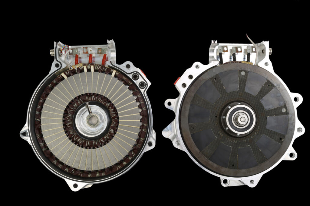
Barriers to high speed in axial flux machines include EM and mechanical effects, the latter affecting the stability of the air gap between the rotor and the stator, which is easier to maintain in cylindrical radial flux machines than disc-shaped axial flux ones
(Courtesy of Integral Powertrain)
Automotive to marine tech transfer
At this point it’s natural to wonder whether there is anything to stop highperformance motors and drives working well in commercial or military marine applications. While automotive motors and drives are not designed for the long service lives expected of most marine applications – and would also have to go through a certification process– in principle it should not be a big issue and would need only a small amount of engineering, Cross says.
The big issue, Maughan remarks, relates again to economies of scale, as many ship programmes produce only handfuls of vessels, sometimes just one or two. “You just wouldn’t commit the resources to do that just to sell one motor,” he says. “We’re in the business of trying to get programmes for 5000, 10,000 or 15,000 motors.”
This implies that the marine industry might look at what is available to the automotive industry and consider adapting it to their applications, rather than asking for bespoke solutions, which seems to be happening to some degree. “We have some motors out there in marine applications, but some large programmes we’ve been approached for haven’t come off. It’s a very low-volume, very distributed market,” Maughan says.
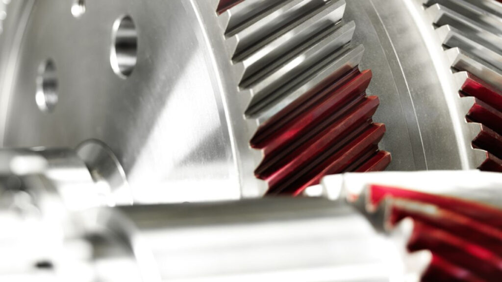
Cutting gear teeth in a helical pattern makes for quieter but less efficient gears
(Courtesy of Voith)
Adaptation to application
Clearly, some engineering would be required to adapt automotive motor and drives to marine applications, particularly with respect to extend their service life, which will have some effects on ultimate performance. Our experts agree that the big things here are electrical insulation durability and bearing life.
“The designs will need better electrical insulation, which results in lower cooling performance and a drop in output, hence the overall machine will have a lower power-toweight ratio,” Lamperth says. “This is similar to automotive engines that are adapted for marine use: their power is substantially lower compared with the automotive version of the engine.”
“They’re the sorts of things that we have a reasonable handle on, so I think it’s a case of fairly straightforward application engineering,” Cross remarks. “I don’t see it having a great impact on the overall levels of the sort of power density you would see in a marine application.”
In an electric motor, certainly of the brushless variety, it is only the bearings that are really subject to wear, and Maughan points out that it is easy to specify a very long life bearing package with minimal impact on weight.
“When you design something like that, you do a bearing life calculation based on the loads you are expecting the bearing to see. You go for a particular design point – 10,000, 50,000 or 100,000 hours, even infinite life,” he says.
It’s also important to look at the rating of the insulation on the copper wires inside the motor, he adds. “Standard insulation ratings can give you a life prediction. Insulation degrades a little when it gets hot, so if you’re going to run it really hot for a very long time, you’re going to need a really high-performance insulation material.”
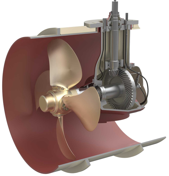
Installing reduction gearing that also turns the drive through 90º allows the use of a fast-spinning motor in the machinery space above
(Courtesy of Kongsberg)
System-level considerations
Beyond adapting motors for a longer service life, there are also system-level considerations to take into account, particularly when deciding between direct-drive and geared transmissions, and integrating cooling systems, for example.
Direct drive is effective and can be simple, Maughan notes, but would mean a relatively large and low-speed motor in a system that needs a 2600 rpm propeller shaft speed.
“If you geared it so your motor could sit at 10,000 rpm instead, you would end up with a smaller motor, but obviously you would need a larger gearbox as a trade-off,” he says. “You would save some money on the motor but you would be adding some cost in the transmission, so there’s a system-level balancing act to perform there.”
Cross emphasises that functional safety would have to be looked at very carefully, particularly with a geared drive because it involves adding another assembly to the system. “It’s important to work out what the failure modes look like,” he says.
“I also think there’s a good case for having an oil-lubricated transmission that sinks its heat into the electric motor cooling. It would be a good and straightforward case of integrating an oil-fed gear into the motor cooling system, and that’s something we’ve done before.”
Maughan adds that there are specific requirements for marine certification and approval, with the need to demonstrate failsafe operation in a variety of scenarios, and there is a difference between PMAC and induction motors in this respect.
“With a PMAC motor you need a mechanical clutch in the driveline, so that if you have a failure in a motor you can physically disconnect it from the propeller. With an induction motor you don’t need that because you just turn the motor off and the induction field in the rotor stops.”
The ongoing pursuit of power-toweight ratio in motors involves the continuous minimisation of losses and the management of heat. The extreme case in this respect involves keeping motors so cold that they can exploit superconductivity. But that is another story, and it’s on page 74.
ONLINE PARTNERS

