


Phase change materials
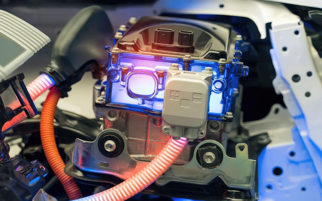
(Image courtesy of Carrar)
Chemical brothers
Phase change materials offer intriguing possibilities in the thermal management of EV powertrains as Nick Flaherty explains
Phase-change materials (PCMs) are known for their superior latent heat capacity, acting as heat absorbers without notable temperature increases. This property can be used in many different ways throughout the powertrain of e-mobility systems, from enhancing the heat transfer in the power electronics to cooling the entire battery pack.
Unlike Peltier heat pumps, fan-based air cooled plates or liquid cooling systems, PCMs provide passive thermal protection without an additional power supply. They can release trapped heat into their surroundings when no heat is transferred internally, making them reversible heat absorbers. PCMs are also considered superior for maintaining thermal uniformity between battery cells.
However, organic materials with relatively poor thermal conductivity make up the majority of PCMs within the optimum temperature range for Li-ion batteries, which therefore limits their effectiveness.
Despite this, phase change materials paraffin and fatty acids are often used due to their relatively constant thermal and chemical characteristics, resilience to corrosives, and they are more affordable than other inorganic materials. Both are currently considered promising materials for battery thermal management applications because of these characteristics as they melt and carry heat away more effectively.
Researchers have added other materials into the paraffin base such as graphite and graphene, metal compounds and nanoparticles to improve thermal conductivity. However, there are still several other limitations, such as weight and environmental side effects, while metal additives in particular require additional protection against corrosion and abrasion. Other PCMs use refrigerant materials that turn from a liquid to a gas to provide cooling for battery packs.
(Image courtesy: 1-Act)
Thermal management
PCMs are increasingly used for thermal management in power electronics. The materials are solid at room temperature which allows them to be easily cut and formed, and are then applied between a power device such as an electronic control unit (ECU) and a heat sink more easily than a thermal grease. This simplifies the steps in the assembly process with less waste and higher reliability as there is no danger of a grease dispenser blocking.
When the ECU heats up, the PCM melts and provides a more efficient thermal pathway from the device to the heatsink. When the vehicle stops, the ECU cools and the PCM solidifies. The phase change material also reacts faster to a change in temperature than greases and pastes, changing from a solid to a liquid to efficiently release and absorb heat for better dissipation and stronger thermal performance.
This comes from the lower thermal impedance value for the PCM, which can be as low as 0.062 compared to a typical value of 0.160 for a thermal grease, with the lower value providing more effective thermal transfer.
In one example, a drive system design had a higher power density than the previous version and so needed a reliable, efficient mechanism to remove the additional heat. Previous experience with conventional thermal grease suggested that, due to inherent material migration (also known as ‘pump out’), a grease thermal interface would not deliver the reliability and performance required. The manufacturing process also needed to be improved.
A phase change thermal interface material with high thermal conductivity of 3.0/W-mK provided higher performance over common thermal greases across two important metrics.
In active power cycle testing, one thermal grease experienced a fatal result after 600 hrs of cycling between temperatures of -50 C to 150 C, while another lasted 800 hrs. The PCM did not fail and the temperature of the chip did not exceed 125 C even after 1,000 hours.
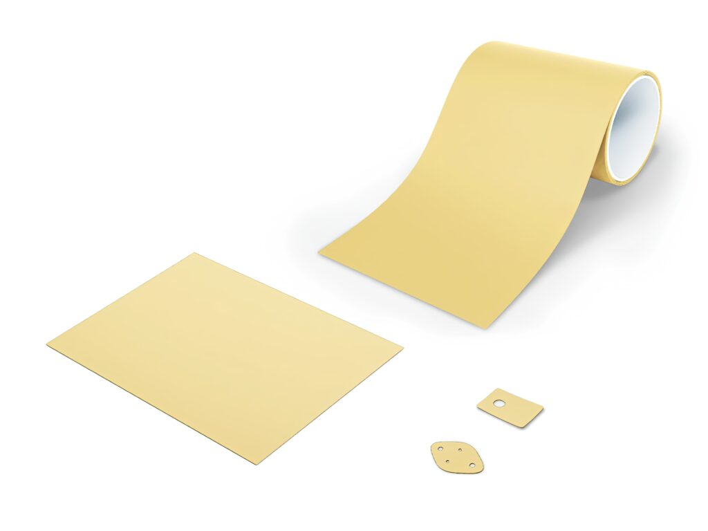
Once applied, the material remains solid at room temperature until the device’s operational heat causes it to melt and spread out across the interface. The PCM can also be applied via stencil printing, allowing an automated, multi-device material application process. Once the PCM material is dried, the PCM layers can be cut to size and stored until needed for system integration.
PCM for battery packs
Using a PCM for cooling a battery pack supports faster charging, where the higher charging rates create higher temperatures in the pack which can be a major issue for the health of the system. It also supports safety, as it can limit thermal propagation. Thermal propagation is the effect where one cell malfunctions and overheats. This can cause neighbouring cells to overheat, leading to a chain reaction and, in the worst case, a battery pack fire.
A cooling system based on a PCM can provide enhanced thermal management over air cooled, particularly with pouch cells. Moreover, as it is a passive system it has a lower energy requirement than a liquid cooled system and potentially higher reliability as there are less moving parts. As more heat is generated in the cells the phase change carries away the initial thermal energy, and then the liquid phase carries heat away through convection rather than the traditional conduction paths of cooling plates.
The cooling in the battery pack can be implemented with a PCM in a number of different ways. The PCM can be contained in cooling units that are interspersed with the battery cells. This is particularly helpful with pouch cells that are stacked together. Cooling modules, often built from lightweight, thermally conducting composite materials such as carbon fibre, can be inserted between the cells to carry the thermal energy away.
Another approach is to have the PCM in the same cylindrical cell format used for the battery cell. This allows the cooling cells to be placed in the battery pack without additional engineering being required.
(Image courtesy of Henkel)
PCM materials
There are a number of phase change materials that are used in battery pack systems, from paraffin as a solid that changes to a liquid, to refrigerant liquids that change into a gas. The choice of the PCM of course leads to different design requirements.
A solid PCM is easier to manage, as shown in the example with the thermal interface to a heatsink, but this makes use of the specific heat of the material. A liquid turning into a gas uses the latent heat of the material, which can absorb more thermal energy but a liquid and a gas need more complex engineering.
Paraffin wax is seen as a suitable phase change material for charging and discharging of a battery cell with a melting point of around 67 C, which is low enough to keep battery cells in a pack at a low temperature.
One investigation into the use of PCMs used a battery pack with cylindrical cells. The paraffin PCM is packaged in cylindrical cells that are the same size as the battery cells and placed in the pack in various patterns. This demonstrated the PCM’s capacity to regulate temperature as well as its practical use as a passive thermal management system for cells with no external power supply.
Employing a PCM has also been shown to provide a longer battery life than without PCM. It improves the energy capacity as 90% of the nominal battery capacity is accessible, rather than 60% with air cooling.
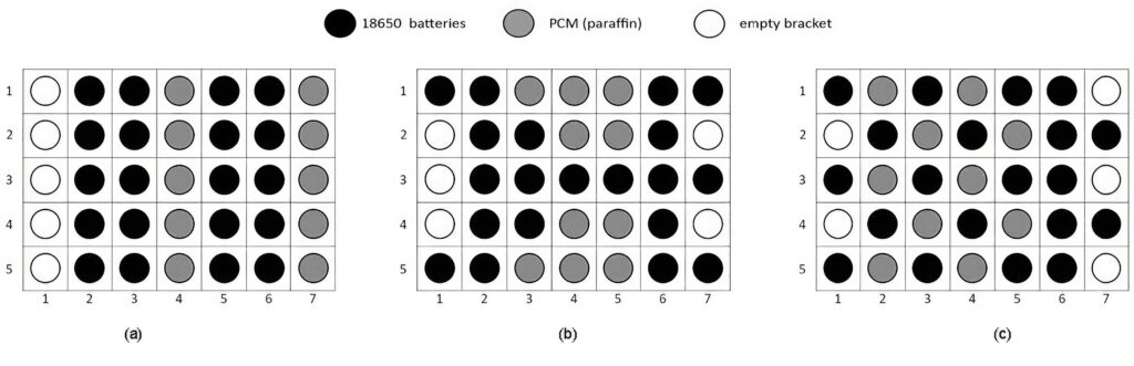
One experiment used three different placements of the PCM cylinders in between twenty 18650 battery cells, and the system was tested based on the measured temperature profiles inside the module under discharge rates of 1, 2, and 4C with charging currents of 50, 100, and 200 A, respectively.
In general, all three configurations showed an average temperature of no more than 40 C and 55 C for 1 and 2C, respectively. In contrast, the 4C discharge test shows only two out of these three configurations could still maintain an acceptable temperature profile below 70 C.
The first configuration, which offers the most straightforward design among the three, would not withstand any constant discharge rates higher than 1C. In such a case, it could be recommended to have a spread-out placement of the PCM tubes in the battery module. That is as in the third configuration, this to prevent the accumulation of dissipated heat around the battery cells, despite a possibly more complex wiring system and installation.
In terms of the degree of temperature uniformity, the minimum values of all three configurations lie within the range of 0.60–0.79.
With the discharge rate of 1C, all configurations could maintain the average temperature below 40 C. However, in a higher discharge rate, the end temperature between the three configurations is different. The average configuration temperature in A reaches around 45 C for 2C discharge.
For the 4C discharge the cut-off temperature was reached quickly so the measurement was stopped on multiple occasions.
This also happened during repeatability tests, showing configuration A could not be efficiently used at the discharge rate of 4C or higher without exceeding the maximum temperature threshold.
(Image courtesy of
Research Center for Transportation Technology)
Composite cooling
Due to the possible mixture of different carbon chains, paraffin tends to have a wide melting spectrum, which makes it more difficult to target the precise phase change temperature.
A composite container for a battery module filled with a PCM wax material was also experimentally tested at various discharge rates.
The average cell temperatures at 1C, 2C, and 4C discharge rates, respectively, might reach 38 C, 50 C, and 70 C in the absence of any heat-absorbing material. The temperature was noticeably lower with PCM present than with a conventional battery module. For instance, at 4C discharge rates, none of the battery cells inside the PCM-filled module were able to reach 70 C.
However the PCM addition also degraded the composite’s tensile qualities. Further investigations used a combination of Paraffin-20 and Caprylone, an organic ketone, as PCMs provide a notably different thermal performance due to their distinctive latent heat profiles. The higher melting temperature of the paraffin mixture, despite its slightly lower latent heat capacity compared to Caprylone, could lead to a more uniform temperature.
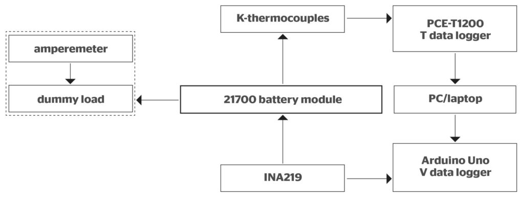
The battery module used in this experiment is made up of nine parallel-arranged (1S9P) 21700 lithium-ion battery cells. All the cells are spot-welded to nickel strips and copper wires to form a single-positive and a single-negative module tab for charging and discharging processes.
The module case was made using MEKP (Methyl Ethyl Ketone Peroxide) and Ripoxy R-804 Vinyl Ester Resin. Two comparable PCM cell cases were also manufactured, each with 20% wt Paraffin-20 mix or the Caprylone PCM. A higher amount of the PCM was tested but the PCM was no longer fully enclosed by the resin of the case, and thus failed the repeated cycle test due to the PCM leaking out.
Then, 5% wt graphite (G) powder was added to the composite mixture to enhance its overall conductive heat transfer. All of these materials were heated in a water bath at 60 °C until all the PCM melted, slowly stirred at approximately 60 rpm for two minutes, and then poured into a 74 mm × 74 mm rectangular mould specifically designed to contain nine 21700 battery cells in a 3 × 3 configuration, with the smallest distance between cylindrical cells being 2 mm.
The composite was then cured for at least 24 hours before its removal from the mould, resulting in a solid battery holder. The contact part with the battery was smoothed with sandpaper before an Arctic MX4 thermal paste (less than 1 g for each module) was thinly applied on its surface to ensure maximum contact and heat dissipation possible from the battery cells to the module. The total weight of each battery module composite is 75± 2 g.
Two separate specimens with the same composition, with and without carbon fibre as a reinforcement material, were built to evaluate their mechanical properties.
The mechanical properties of the composite are typically compromised by the inclusion of paraffin, where the ability to resist mechanical stresses is nearly 70% lower than the composite without PCM. Graphite has the benefit of creating a more evenly distributed mixture and improving overall heat transfer, but it also further reduces the maximum force and stress.
Unfortunately, it is still challenging to fabricate a reinforced PCM composite battery module, particularly properly fitting the carbon fibre in between the battery cells. Further developments to investigate the module strength under other direct mechanical abuses, such as object penetration and long-term vibrations, as well as vehicle crashes, are ongoing.
Overall, both paraffin and Caprylone can be used as a PCM for passive protection against any potential thermal abuses in EV battery modules, while in terms of mechanical strength, the use of a composite reinforcement material is strongly encouraged.
(Image courtesy of
Research Center for Transportation Technology)
Inorganic salts
Another type of PCM is based on inorganic hydrated salts, which are salts in water solution. Generally, it is a saturated solution and initiates crystallisation at phase change temperature. This potentially provides an ideal phase change behaviour as it melts isothermally similar to a pure material.
These have low thermal expansion, good latent heat and thermal conductivity, are non-toxic and are non-flammable. But they are corrosive and the phase change reversibility is challenging to retain for a longer duration.
The temperature for the operation of the system must agree with the PCM phase change temperature. In case of Li-ion battery packs it is in the range of 20–25 C.
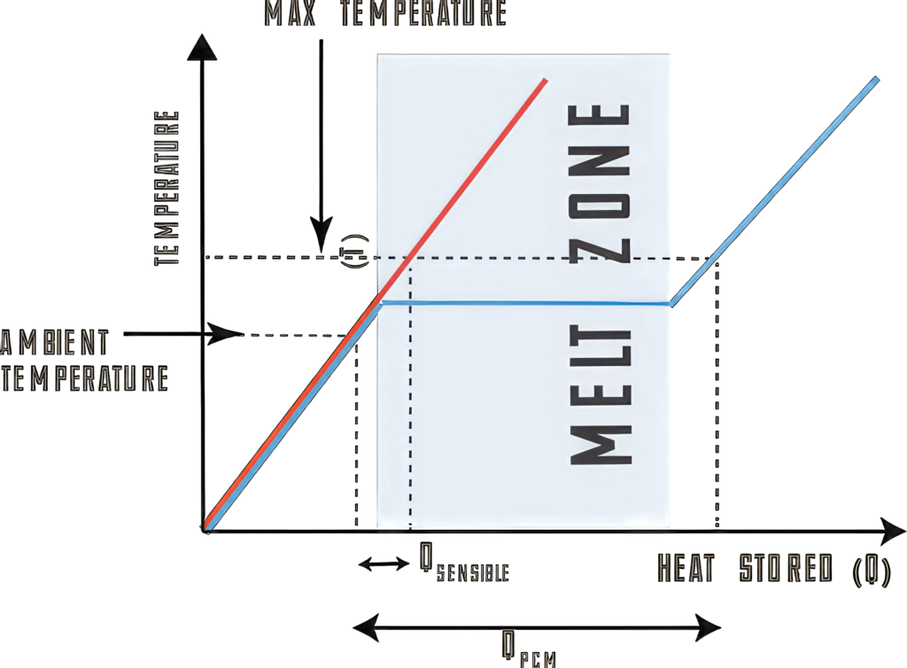
To gather all the heat created by the system, the PCM must have high latent heat and high thermal conductivity for allowing rapid transfer of heat and its storage. This is determined using differential thermal analysis (DTA) and differential scanning calorimetry (DSC) to compare the exchanged heat or temperature development up to a reference sample during a test with the evolution of a preconfigured temperature.
In most cases, highly conductive materials are made of metals or carbon-based compounds. Metal fins inserted inside a PCM casing, graphite foam, or metal foam might be the major approach. The technique is straightforward, and thermal conductivity may be significantly increased, up to 4500 percent of the PCM’s original thermal conductivity.
Another approach is to add powder, nanotubes or nanoparticles to the PCM. Various nanostructures have shown different results, ranging from 7 to 1000% increase in the initial PCM thermal conductivity. However, producing the composites is difficult as it can be difficult to get a homogenous carbon nanostructure dispersion in the PCM.

Open cell metal foam with improved thermal conductivity for the continuous skeletal structure, lower apparent density, homogeneously dispersed pores, and stronger structural strength are used to increase the thermal conductivity of the PCMs.
One approach is to use pure paraffin with a copper or nickel foam to carry away the heat energy. For a copper foam with a pore size of 25 PPI (pores per inch) and a porosity of 88.89%, 92.31% and 96.95% showed thermal conductivity 44, 31 and 13 times greater than that of pure paraffin.
A copper foam with 97% porosity could enhance the PCM thermal conductivity up to 5 W/m/K.
An Expanded Graphite Matrix (EGM) is similar to a metal foam and has a similar high thermal conductivity, stable shape, low apparent density and porous internal structure and is easier to produce, although it is harder to produce a homogeneous structure.
Safety
A patented phase change composite (PCC) material using graphite has been tested in a thermal runaway of a 450 Wh lithium-ion battery pack. This has good heat rejection due to its high thermal conductivity (20 W m−1 K−1) compared to air (0.024 W m−1 K−1) or potting compounds (∼2.5 W m−1 K−1) typically used in packs of cylindrical cells.
Experimental nail penetration studies on a Li-ion pack for small electric vehicles, designed with and without PCC, show the effectiveness of PCM thermal management for preventing propagation when a single cell enters thermal runaway.
When parallel cells short-circuit through the penetrated cell, the packs without PCC propagate fully while those equipped with PCC show no propagation. In cases where no external short circuits occur, packs without PCC sometimes propagate, but not consistently. In all test conditions, the use of PCC lowers the maximum temperature experienced by neighbouring cells by 60 C or more.
Adding PCM to the EV battery module or pack comes with its own challenges. The use of porous materials such as metal foams to store the PCM has been extensively studied but faces a challenge from the way the material is inserted into the pack and the volumetric change during phase change.
Another possibility is to submerge the battery module or pack in a tight container filled with a PCM. Although this design likely produces a greater temperature uniformity, the wiring complexity and huge addition of weight are the main drawbacks.
Solid to solid phase change
There are also phase changing materials with phase change during solid to solid phase. Alteration in the crystal lattice of the material is the characteristic of such phase change. However, because the phase change temperature ranges from 80 to 180 C, the application regions are limited.
Liquid phase change
Liquid PCMs can also be used to carry the heat away from the battery cells in a pack, but this can require more complex engineering to gain the advantages of the phase change. The system is engineered to reduce the temperature difference between the boiling point and the cell, by changing the pressure to adjust the boiling point. The aim is to achieve a boiling point within one or two degrees of the operating temperature of the cell of around 25 C.
The heat from the cells boils the PCM, generating gas to remove the thermal energy from the cells. This gas circulates through the system to a condenser, where the heat is removed and the gas liquifies and is re-circulated through the battery pack. The condenser is typically four times more efficient than a radiator, so a 30 to 40 kW condenser supports high C rates of 2C or 3C continuously.
Battery pack
The biggest reservoir is the battery modules, with a volume of typically 20 litres for a 100 kW pack and 2 litres in the rest of the system. A condenser measuring 60 x 40 cm and 30 mm capacity thick can dissipate 25 kW while keeping the batteries at 25 C. This is typically, and deliberately, the same size as a radiator for a traditional liquid cooled system so there is no additional space required to implement the liquid PCM system.
Keeping the cells at a constant temperature also extends the lifetime and the usable capacity of the battery pack. In tests with cylindrical NMC lithium ion cells charging and discharging at 2C using a liquid phase change system, a 100 kW pack took 2400 cycles before reaching 80% capacity, compared to 600 cycles for a liquid cooled pack.
The pack also stays above 90% capacity for 2200 cycles rather than dropping below 90% at 400 cycles. This is important for the secondhand market as the battery pack with PCM cooling would last several years longer than one without. The system has also been tested with prismatic cells to over 1000 cycles and with lithium iron phosphate (LFP) cells.
Next generation dual phase liquids
However the dual phase liquid suppliers are targeting a temperature of around 50 C as the sweet spot to cover the rest of the system, such as inverters and power modules.
The current dielectric fluids in development such as 2P50 have a 50 C boiling point and a low global warming potential figure of 10 for the environmental impact with zero ozone depletion potential (ODP). The proprietary hydrofluoroolefin (HFO) dielectric fluid is intended for commercial launch in 2025, doesn’t have a flash point and can be classified as a flame suppressant. The aim is that this can be used for a lot of different systems that have heat that needs to be managed and avoids having many different fluids in the vehicle to manage.
The dielectric strength, or the ability to insulate the electronic components from each other electrically as well as thermally is also key to reducing the size of the inverters and modules by allowing components to be closer together. The dielectric is specifically tested for the density of electronics it supports.
In some cases there is an opportunity to pressurise the system, but at 50 C it is still a low pressure system at a few psi; less than 10 psi. This minimises the risk of leaks and makes designs easier to develop.
The higher boiling temperature is not a problem even for battery packs as it is the hot spots in the pack that cause a lot of the stress. The dual phase boiling point reliably limits any cell to 50 C and avoids the risk of thermal runaway or damage to the cells, particularly with faster charging.
Where things start getting really interesting is what comes after lithium ion cells. Solid state batteries for example operate at the higher temperatures; some battery types may have higher temperature operation.
The dual phase materials allow more focus on holistic thermal management, using the heat from the battery to heat the car in the winter and providing more effective methods for managing the heat with less radiators rather than just getting rid of the heat.
Conclusion
There are many types of phase change material used in different areas of an electric vehicle. Some are designed to provide a more efficient thermal interface in power electronics, and the materials are designed to be easy to use in the assembly process, cut into templates and able to be stored for long periods before being assembled.
But the real opportunity for PCMs is in the cooling of battery packs. The basic paraffin wax turning from solid to liquid can carry heat away from battery cells. Mixed with other PCMs, the wax can provide more thermal capacity.
Adding in graphite or carbon fibres can provide more structural strength and further boost the thermal capacity, but this can cause more abrasion with the rest of the pack. This is a key engineering balance that is still being addressed, as the additives can cause abrasion in the battery pack as the PCM melts and solidifies. The heat can be carried out with passive heat pipes, reducing the complexity of the battery pack design and assembly.
Liquid phase change materials can avoid the abrasion issues, but require other components such as a condenser, even if this replaces an existing radiator. The higher latent heat capacity of the liquid phase maintains the temperature even with high charging and discharging rates and boosts the lifetime of the battery pack. There is further discussion on the technology specifically for immersion cooling on page 58 of this issue.
Acknowledgments
With thanks to Eitam Friedman at Carrar, Brandon Marshall at Chemours and Alexander Budiman at the Research Center for Transportation Technology in Indonesia.
Click here to read the latest issue of E-Mobility Engineering.
Some suppliers of phase change materials for thermal management
Germany
Axiotherm GmbH
Henkel AG & Co KGAA
Rubitherm Technologies GmbH
Hong Kong
+49 36691 53 118
+49 211 797 0
+49 30 7109622 0
Italy
India
United Kingdom
Croda Europe Ltd
Phase Change Products Pty Ltd
+44 1405 860 551
+44 1733 245 511
USA
Advanced Cooling Technologies, Inc
Boyd Corporation
KULR Technology Group, Inc
Microtek Laboratories, Inc
Parker Hannifin Corporation
PureTemp LLC
Chemours
Vietnam
+1 717 295 6061
+1 888 244 6931
+1 408 675 7002
+1 937 236 2213
+1 800 272 7537
+1 952 941 0306
+1 302 773 1000
ONLINE PARTNERS
