


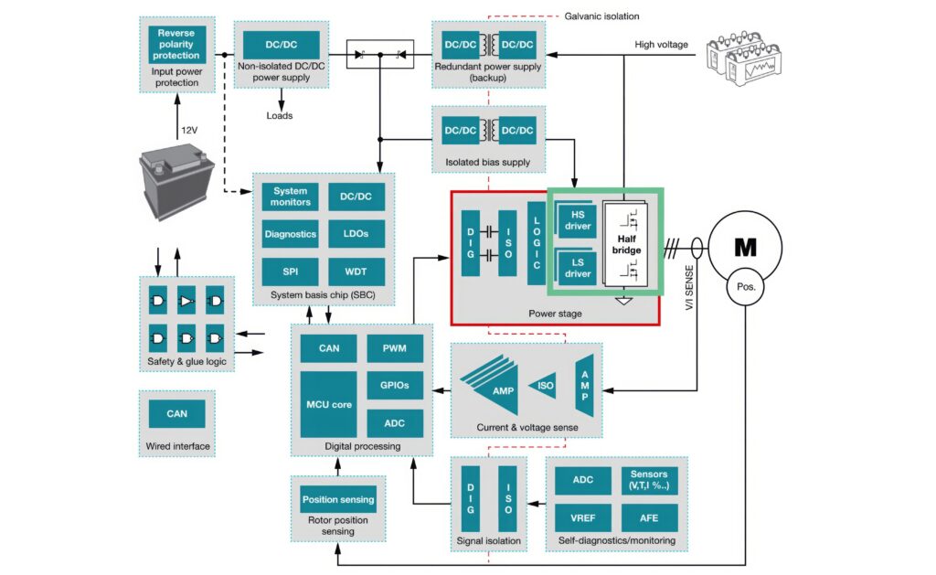
Motor control

(Courtesy of Renesas Electronics)
Looking for the perfect wave
Nick Flaherty explains the various ways to create the perfect sine wave to maximise the efficiency of electric motor control
Improving the efficiency of e-mobility motor control is a key focus for developers. Design technologies to squeeze the last microamp out of the battery can boost the range of EVs significantly, while improving the efficiency of the motor control can reduce losses, cutting the amount of thermal management needed and so reducing the complexity and weight of a motor.
All of this comes down to the quality of the sine wave that controls the motor. Generating it is a complex task and varies with the individual motor design. Any deviation from the perfect sine wave, from jagged peaks to variable timing, lowers the efficiency of the output from the gate drivers that feed the switching transistors. These can be IGBT silicon transistors, silicon carbide (SiC) MOSFETs or gallium nitride (GaN) transistors.
Control algorithms are optimised for these different types of transistors, in a complex development process for hard-switching topologies.
Hard-switching is the most common technique for DC-AC power converters but it has numerous drawbacks, the largest of which is the introduction of switching losses when a transistor fully transitions between On and Off states. These losses are responsible for a large percentage of power converter losses.
Pulse width modulation
Pulse width modulation (PWM) is the most common hard-switching technique for generating a sine wave. The size and timing of each pulse builds up the wave, and on an engineer’s bench it is possible to generate a suitable sine wave. However, with constant changes in load, current, voltage and temperature is it difficult to reduce the total harmonic distortion.
EVs are mostly driven in the low to mid-power range, so reducing the switching losses in this range will greatly improve the efficiency in terms of battery usage time and mileage.
SPWM (Sinusoidal PWM) is the most predominant PWM technique in inverter technology. The pulses are generated by comparing a reference sinusoidal signal as a modulating signal with the carrier signal. The carrier wave determines the switching frequency and the modulating wave which determines the frequency of the output wave. The frequency and amplitude of carrier wave frequency are higher than the modulating wave
The amount of harmonic distortion is minimised by varying the modulation index, which is determined by the amplitude of the generated pulse. The higher the carrier frequency, the smoother the output waveform. IGBT devices can only switch at 10-20kHz, SIC up to 200 kHz and GaN up to 2 MHz.
Multiple phases
Multi-phase machines have many advantages such as smoother torque and low stator current in the motor at each phase without increasing the stator voltage per phase. By implementing a nine phase drive system the stator current is reduced at each phase, in turn reducing the size of bulky components used in a conventional three-phase system, and reducing the need for series connection of large numbers of batteries, improving the safety of the system.
The nine-phase machine consists of nine stator windings operate at an angle of 400 phase shift (3600 ÷ 9). Each winding is energised by a separate inverter leg triggered by individual PWM signals at intervals of 400º out of phase with each other.
Naturally the nine-phase inverter consists of nine legs, each leg consisting of two semiconductor transistor switches connected in series. That means they are in the same leg and will be in the On or Off state depending on control signals generated by the PWM signal. SiC MOSFETs are used as semiconductor switches at each leg for the higher frequency, and for the simulation the load is a star-connected RL load.
Another important factor in designing a nine-phase inverter is the nonlinear characteristic of the EV power profile. Non-linear loads cause harmonics in electrical power converters, resulting in a poor power factor and high switching losses. To overcome these issues, various PWM techniques are used that vary the modulation index to minimise harmonic content. These include SPWM and Space Vector Pulse Width Modulation (SVPWM).
Simulations show that SVPWM produces fewer ripples than SPWM, while the power output of SPWM can be improved by using a suitable filter circuit. Compared with SPWM, SVPWM has better performance but is more complex to implement.
(Courtesy of Pre-Switch)
New techniques
Another new variable switching frequency pulse width modulation (VSFPWM) strategy aims to improve EV inverter efficiency. A SiC MOSFET inverter has excellent switching characteristics, enabling pulse width modulation control with a high switching frequency.
The high switching frequency can reduce the voltage ripples in DC-link capacitors, which enables their use at a reduced capacitance. The switching frequency is typically set to a level that is within the limits of the voltage ripple in the maximum output region.
Given that the same switching frequency is applied to the entire operating region, there is sufficient margin with respect to the limits of the voltage ripple in the low-to-medium output range. VSFPWM is designed to consider the real-time minimum switching frequency by considering the voltage ripple of the capacitor during operation under loaded conditions, thereby minimising the switching loss.
In addition, the method is suitable for high-switching frequency control because the calculation time is short. Because it does not require additional hardware, it is also easy to apply to an existing inverter.
In an inverter design, the DC-link capacitors, power semiconductors, cooling systems, connectors, and control units account for 23%, 17%, 20%, 15%, and 25% of the power losses respectively. The switching performance of a SiC MOSFET allows a reduction in the size of the cooling system as well as the size of the DC-link capacitor.
The design of a DC-link capacitor should consider its lifetime and capacitance, which is determined by the root-mean-square (RMS) value of the current ripple of the capacitor. The variation in the RMS current ripple with respect to the switching frequency is insignificant.
The capacity of the DC-link capacitor is determined by the voltage ripple. Given that this ripple exhibits a large variation with respect to the switching frequency and has an inverse relationship with it, it is possible to reduce the capacitor’s capacity by increasing the switching frequency.

The switching frequency satisfies the voltage ripple condition of the capacitor in the maximum output range of the load. When the inverter is driven according to the constant switching frequency PWM strategy, the voltage ripple has a sufficient margin compared with the limit value in the operating range lower than the maximum output.
With an IGBT inverter, even if a separate switching frequency is selected in real time according to the capacitor voltage ripple margin, the typical range of the variable switching frequency is limited to 6-10 kHz. If the optimal switching frequency is selected for each operating range, a major improvement can be achieved in terms of the switching loss.
There is active research on the VSFPWM strategy to improve inverter efficiency.
The voltage ripple is a key design factor of the capacitor, as this has an impact on the control stability of the inverter and the voltage utilisation ratio. The problem of voltage ripples also affects the battery’s state of health.
However, with this approach, a separate current sensor needs to be added to the input side of the inverter, and the voltage ripple is observed through the integration of the sensed current. This involves an increase in the inverter cost.
Also, it is not easy to apply this method to SiC MOSFET-based high-switching frequency PWM inverters, because of the increase in the calculation time required for analogue-to-digital (ADC) conversion of the sensed current and the related signal processing.
To address these limitations, the VSFPWM strategy is based on a mathematical model of voltage ripple and does not require additional hardware, such as sensors or circuits. The voltage ripple factor is extracted in advance and incorporated into the algorithm.
In operation the switching frequency is determined through the minimum calculation between the pre-calculated ripple factor and the load phase current. Because the real-time calculation is thus minimised, the calculation time is short, which makes it suitable for application to the SiC MOSFET-based PWM inverter, which operates at a high switching frequency.
(Courtesy of Texas Instruments)
Machine learning
One emerging technique for producing that perfect sine wave is to use machine learning (ML) for soft switching. This soft switching minimises switching losses but it has never been successfully implemented for DC-AC systems with varying input voltage, temperature and load conditions.
The ML framework has been trained on signals for motors and drivers with varying input voltage, temperature and load conditions.
Once trained, the framework runs on a controller board and can double the power output for a typical inverter, or provide an increase in switching speed by a factor of up to 20.
The ML constantly adjusts the relative timing of elements within the switching system required to force a resonance to offset the current and voltage wave forms to minimise switching losses.
This forced-resonant soft-switching topology replaces the traditional IGBT or SiC driver with a common intelligent controller board and a specific resonant power gate module optimised for SiC or IGBT transistors.
The topology is a variation of the Auxiliary Resonant Commutated Pole (ARCP) soft-switching converter design with embedded AI to solve complex switching system timing calculations dynamically to ensure accurate soft-switching under changing input voltage, output load, device tolerances, and temperature changes. Adaptations are made on a cycle-by-cycle basis to minimise losses and maximise efficiency.
This can reduce the losses in the iron core of the electric motors at cruising torques to increase an EV’s range by up to 12%. A 200 kW inverter reference design shows the technique reduces total system switching losses by 90% or more.
That then enables switching frequencies four to five times faster than hard-switched IGBT systems and 35 times faster than hard-switched SiC and GaN systems, and requires only half the number of transistors. This higher frequency can also improve the efficiency and reduce the size of the magnetics, reducing the weight of the powertrain.
In the case of an SiC-based EV inverter, increasing the switching frequency from 10 to 100 or 300 kHz creates a near-perfect sine wave without any output filter, and achieves 99% efficiency. The result is the elimination of unnecessary motor iron losses and an increased motor efficiency at low torque and low rpm. Higher switching frequencies also enable higher rpm motors that are lighter and lower cost.
The inverter exceeds 99.3% at 100 kHz using only three discrete, low-cost 35 mΩ SiC MOSFETs, one for each phase.


The ML algorithm constantly predicts the zero voltage switching point. The controller analyses multiple inputs on a cycle-by-cycle basis, making adjustments in real time to small, forced-resonant transistors, enabling perfect soft-switching in harsh changing environments. Variations in system temperature, device degradation, changing input voltages and abrupt current swings are all accounted for and optimised within the ML algorithm.
The algorithm controls the current that charges the capacitors for around 100 ns at the zero-voltage, zero-current point. This adjusts the timing of the switching with an accuracy of 2 ns every cycle. Other algorithms can do this for certain points in power, but it’s the infinite variety of changing conditions that creates the problem, which is why ML is used for the prediction.
This takes in data that’s incomplete and in a noisy environment, and calculates where the switching will be. It monitors the device temperature and device switching speeds, and measures how it reacts and degrades over time to allow the algorithm to compensate for these changes. There is some pattern matching, but the algorithm calculates the individual responses of each transistor on a cycle-by-cycle basis.
The evaluation data shows the switching technology hits a peak of 99.57%, with 98.5% efficiency at 5% load in the 200 kW inverter design with 100 kHz switching.
The efficiency at low loads and the low distortion for the high-frequency sine wave to the motor are key to improving the WLTP range performance.
Gate drivers
IGBT and SIC MOSFETs have similar requirements for motor control. IGBTs need -8 V in the Off state to +15 V in the On state, while the SiC MOSFET voltage varies slightly, from +18 or +20 V in the On state to -5 V in the Off state. These are close enough for a single gate driver to drive either type of transistor if designed appropriately. GaN transistors on the other hand need drivers that range form -2 to -5 or -6 V, and so need different gate driver designs.
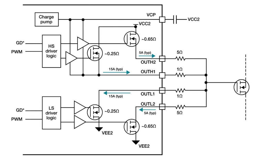
The gate-driver IC has to turn on the SiC FETs as efficiently as possible, while minimising switching and conduction losses that include the energy used during the ‘turn on’ and ‘turn off’ process, which has to be as fast and efficient as possible.
The ability to control and vary the gate-drive current strength reduces switching losses, but at the expense of increasing transient overshoot at the switch node during switching. Varying the gate-drive current controls the slew rate of the SiC FET.
Real-time variability of the gate-drive current enables transient overshoot management as well as design optimisation throughout the high-voltage battery energy cycle.
A fully charged battery with a state of charge from 100% to 80% should use low gate-drive strength to minimise the SiC voltage overshoot. As the battery charge drops from 80% to 20%, using high gate-drive strength reduces switching losses and increases traction inverter efficiency. These scenarios are possible during 75% of the charging cycle, so the efficiency gains can be quite significant.
A 20 A isolated real-time variable gate driver adds a highly configurable adjustable slew-rate gate driver targeted to drive high-power SiC MOSFETs and IGBTs, and squeeze as much current out of the system as possible.
Power transistor protections such as shunt resistor-based over-current, temperature sensors and desaturation (DESAT) detection, including selectable soft turn-off or two-level soft turn-off during these faults. To further reduce the size of the motor control system, an active Miller clamp and an active gate pull-down can be integrated into the driver. An integrated 10-bit ADC enables monitoring of up to two analogue inputs, the voltage supply, the DESAT and the gate driver temperature.
Diagnostics and detection functions are integrated to simplify the design of ASIL safety
The parameters and thresholds for these features are configurable using a standard serial peripheral interface (SPI), which allows the device to be used with nearly any SiC MOSFET or IGBT.
A standard way to evaluate a traction inverter’s power-stage switching performance is the double pulse test (DPT), which turns the SiC power switch on and off at different currents. Varying the switching times makes it possible to control and measure the SiC’s on and off waveforms over the operating conditions, allowing the efficiency and SiC overshoot, which affects reliability, to be evaluated.
The results in Table 1 show how an SiC gate driver with variable strength allows any overshoot to be controlled while maximising efficiency and optimising thermal performance.
The waveforms can show the effect of variable gate-drive strength on SiC overshoot, as the gate-drive resistance and drive strength are controlled in real time. Enabling the lower gate drive (SiC turn-off) mitigates the power stage overshoot.
A strong gate drive can reduce SiC switching losses with a significant efficiency gain, depending on the traction inverter’s power level. While the choice of gate driver will dictate the overall efficiency of the power stage through the reduction of switching losses, the choice in gate driver bias supply can contribute by limiting conduction losses.
Modelling with the WLPT procedure and real drive log speed and acceleration settings has shown SiC power-stage efficiency gains as high as 2%, corresponding to an additional 7 miles of range per battery, which can add up to over 1000 miles per year for an EV user. Seven miles could mean the difference between a consumer reaching a charger and becoming stranded.
(Courtesy of Texas Instruments)
Higher voltages
To accommodate the higher voltages of EV batteries, another gate driver has a built-in 3.75 kVrms (kV root mean square) isolator, which is higher than the 2.5 kVrms isolator in previous devices and can support power devices with a withstand voltage of up to 1200 V for 800 V and 1000 V battery packs. This provides data transfer with high-voltage isolation between the primary circuit (on the microcontroller side) and the secondary circuit (on the IGBT side)
The driver boosts the CMTI (Common Mode Transient Immunity) performance at 150 V/ns or higher, providing reliable communication and increased noise immunity while meeting the high voltages and fast switching speeds required in inverter systems. The gate driver is packaged in a small SOIC16 package for smaller inverter systems.
For heavy-duty off-road EVs, a dual channel gate driver operates at up to 1000 V. The gate driver provides automotive-related protection functionalities and diagnostics. A galvanic isolated IGBT module integrated NTC read-out provides IGBT module temperature information.
This supports a PWM switching frequency of up to 20 kHz and uses 1.5 W per channel at maximum ambient temperature.
Single-phase PWM measurements
PWM of the output of motor drives makes capturing stable measurements of signals challenging. Manually determining the right combination of filters and triggers to achieve stable waveforms is very difficult, yet this is a prerequisite for achieving consistent measurements.
In addition to measuring the output of the drive, measurements to evaluate the performance of the drive’s input stages such as harmonics, power and power factor are also important. While exporting raw waveforms into a spreadsheet or other analysis software is possible, the process is time-consuming and requires care in designing calculations.
The measurements involve many connections to the device under test. Incorrect probing of the motor drive system and poor integrity of connections are common sources of errors in making motor drive measurements.
Mechanical measurements are also key and can be made using sensors. However, it can be difficult or impossible to get measurements in engineering units of speed, acceleration or torque without custom processing and scaling.
For these reasons, getting a good view of a motor drive system with an oscilloscope requires careful set-up, stable waveforms and robust measurement algorithms.
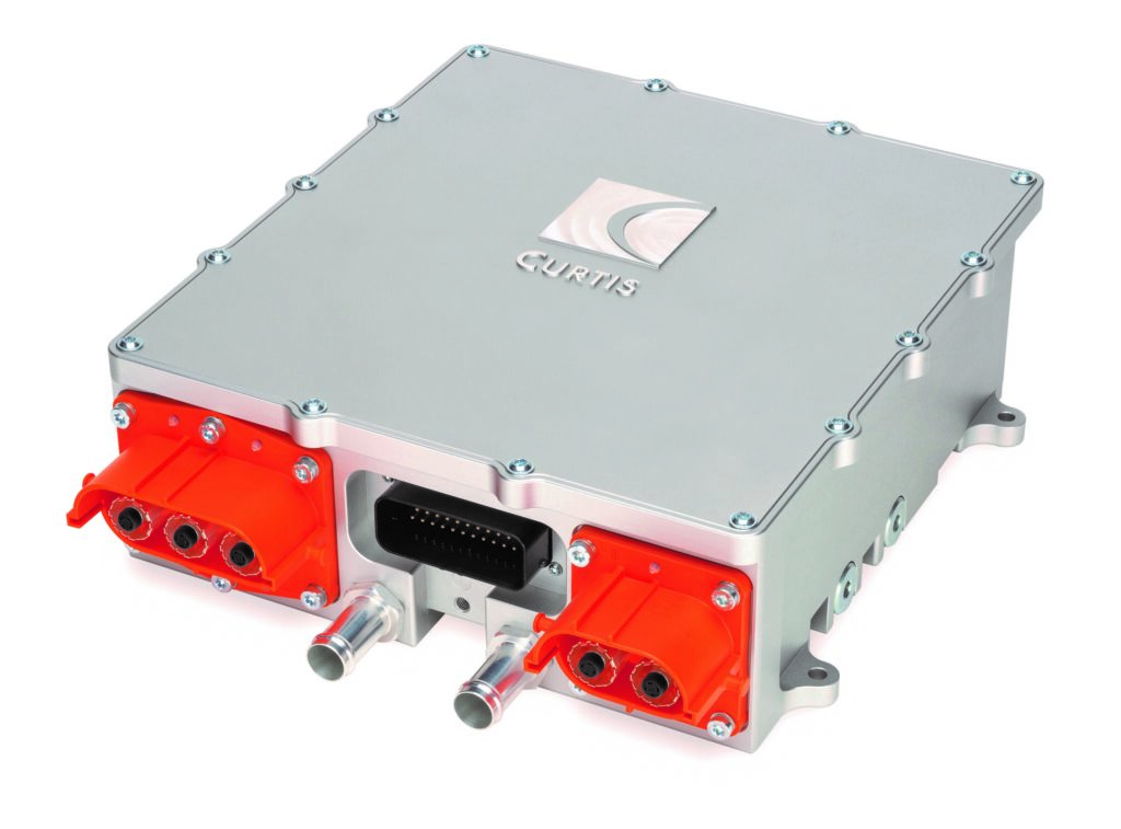
(Image courtesy of Curtis Instruments)
Vector drives/field-oriented control
The more advanced drives for AC induction motors and synchronous motors use vector drive techniques. These are more flexible and efficient than scalar drives, but also more complex.
Vector drives have similarities with scalar ones in that they drive the motor with sinusoidal current; however, vector drives provide smoother operation, quicker acceleration and superior torque control. These control systems often use field-oriented control using two orthogonal vectors whose magnitudes relate to the torque and magnetic flux within the motor.
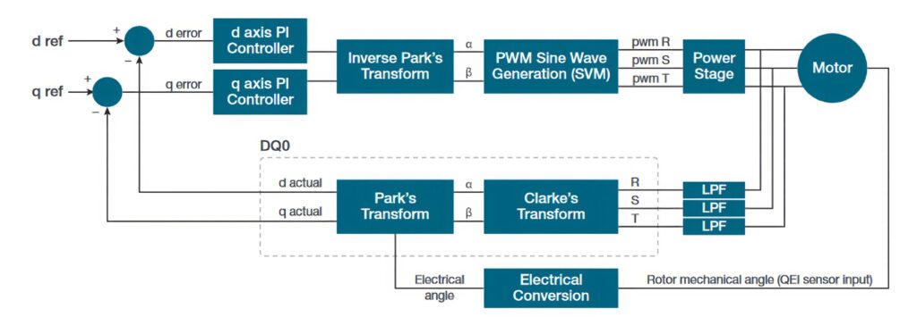
The control system must measure the position of the rotor in order to synchronise the system. This is often done by using sensors such as Hall sensors or a quadrature encoder interface. (Sensorless systems are also used in which the control system uses the back-EMF of the motor to determine rotor position.) The controller uses the Clarke and Park transform to calculate the magnitudes of the vectors then uses these values as setpoints for the control loop.
Motor drive measurements involve relatively high voltages. For example, the DC bus voltage in a 480 VAC three-phase motor drive is typically around 680 VDC, while the common-mode voltages can also be relatively high.
Field-orientated motor control algorithms maintain optimal performance for three-phase AC motors under all operating conditions. Real-time motor torque and power estimates optimise the power of the motor using a combination of customised field-oriented control algorithms and PWM switching to provide torque and system efficiency across the entire torque/speed spectrum.
A dual-core microcontroller can allow additional code to run on the motor controller to act as a system controller, eliminating the need for costly additional controllers. This is particularly suitable for equipment such as materials handling trucks, mobile elevating work platforms, airport round support and construction equipment.
Wiring configurations
Both the input and output of variable-frequency drives (VFDs) often use three phases. However, some VFDs used by automotive drive systems might be powered by single-phase AC or DC. In addition, three-phase systems can be wired and modelled in two configurations: star and delta.
The wiring configuration determines the calculations used in power analysis, so it is important to understand and select the correct wiring configuration in order to get the expected results. These configurations apply to both the inputs and outputs of motor drives.
Even though only two wattmeters are required to measure the total power in a three-wire system, there are advantages to using three. The three-wattmeter configuration requires six oscilloscope channels: three voltages and three currents.
This 3V3I configuration provides individual phase-to-neutral voltages and the power in each individual phase, which is not available in the two-wattmeter configuration.
For three-wire systems, measured with 3V3I, the IMDA software includes a setting to convert line-to-line (L-L) to line-to-neutral (L-N) voltages. Although there is no physical neutral in this system, it is possible to determine the instantaneous line-to-neutral voltages from the instantaneous line-to-line voltages.
This point-by-point LL-LN conversion expresses all voltages relative to a single reference and corrects the phase relationships between voltage and current for each phase. Turning on LL-LN conversion allows instantaneous power calculations by multiplying phase-to-neutral voltages and phase currents.
Three voltage channels and three current channels are required to measure the total power in a system that uses a neutral conductor between the line and the drive, or the drive and the motor. The voltages are all measured relative to the neutral. Phase-to-phase voltages can be accurately calculated from the phase-to-neutral voltage amplitudes and phases using vector mathematics.
It is recommended to use built-in software in an oscilloscope that includes a three-phase autoset function, which automatically configures voltages and current sources based on the selected wiring configuration. It will optimally set up the vertical, horizontal, acquisition and trigger parameters on the oscilloscope and can be done on all active power measurements.
This greatly simplifies measurement set-up, especially for PWM waveforms on the output of the VFD, enabling faster and more accurate measurement.
(Courtesy of Tektronix)
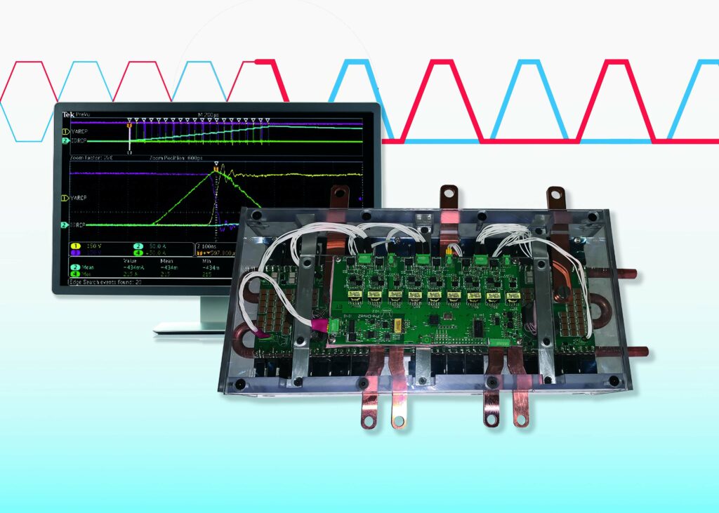
Embedded oscilloscope
Another advantage of using ML in a controller is the ability to tap into key remote monitoring and diagnostics.
An embedded digital oscilloscope enables designers to diagnose exactly what is occurring remotely, and then make adjustments in situ. This gives developers 12 channels and 160 Msamples/second with the ability to analyse the timings of the switching. Traces can be recorded and exported out to see how the system is performing.
This enables developers to understand what is happening in the motor control system so that actions can be taken. In the future, preventative maintenance programs may be able to be implemented, using the feedback from the embedded oscilloscope in the motor controller.
Although the idea of soft switching is not new, it had not previously been possible to implement it in an inverter with continuously varying input and output conditions.
Conclusion
Creating the perfect sine wave is a key challenge for EV motor control. More techniques are being developed to improve the efficiency of the motors, and there are associated challenges for measuring the signals.
New PWM modulation schemes and multiple phase designs can boost the efficiency, but can be more complex and costly to implement. ML is being applied to the motor control signals to improve the motor efficiency above 99% while reducing the complexity of the inverter.
The ML approach also enables an embedded oscilloscope to give a more detailed view of the signals and can even predict how the motor will behave. This can warn of problems elsewhere in the inverter and motor system as the signals fluctuate out of the expected range, predicting potential problems and enabling maintenance to be scheduled before a catastrophic inverter or motor failure.
Acknowledgements
The author would like to thank Bruce Renouard and Jacek Borecki at Pre-Switch, Lee Miller at Tektronix and George Lakkas at Texas Instruments for their help with researching this article.
Click here to read the latest issue of E-Mobility Engineering.
Some suppliers of motor controllers
China
Bacancy
Curtis Instruments
Electromate
Matsusada Precision
Sensata Technologies
STMicroelectronics
Texas Instruments
UK
+1 347 441 4161
+1 914 666 2971
+ 1 877 737 8698
+1 704 496 2644
+1 508 236 3800
+ 1 972 466 7775
+1 972 995 2011
ONLINE PARTNERS
