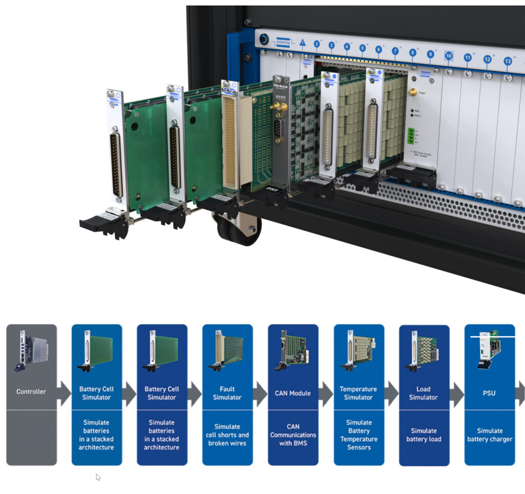
Modular PXI-based BMS tester

Pickering Interfaces has developed a modular test system for battery management systems (writes Nick Flaherty).
The system is based around the PXI standard, and combines a range of modules for fault injection and emulating battery cells, including when they are on fire. It measures the resulting temperature, current and voltage at the BMS while in operation and during charging and discharging.
“We started off as a PXI test systems provider when we saw a need for testing a BMS, whether that is when designing the BMS or end-of-line testing,” said Noman Hussain, VP for software and strategic business development.
“The technology is growing but it is not mature, and BMS plays an important part – as the battery chemistry changes, so do the current and voltage, so there are a lot of challenges,” he said. “Customers have developed universal test systems for BMS master as well as slave systems.”
Pickering also supplies reed relays and uses them for a fault insertion module. “The module can simulate what will happen if wires in a battery pack are cut or have a reverse polarity. These have switches in the middle that we can switch to provide different faults,” said Hussain.
The 4190P fault insertion module has 74 channels with 36 lines to two different fault lines, each with four faults. These can be connected together to create a short, ground, or voltage high to simulate lots of different fault conditions and see what will happen to the BMS in those circumstances.
“We have also created a module that emulates six battery cells in a single PXI card,” said Hussain. “This combines products from other vendors to create a test system, and you can stack the modules and chassis together to emulate a whole battery pack, which allows you to test different fault conditions for the BMS.”
Another part of the system is an RTD programmable resistance simulator that provides high-temperature readings without actually using a battery pack that is on fire, and is used in a lot of different test scenarios to test fault conditions. A programmable module can emulate any type of cell chemistry.
“We also have a 0-7 V power supply module that you can programme according to the cell profile, with independent monitoring circuitry so it can act as a cell and as verification for the BMS, and can also source and sink,” said Hussain. “We haven’t put any battery profiles on it, as every cell chemistry is different, but we provide an API to develop the profile, and we provide Windows and Linux drivers so developers can programme in tools such as LabView or languages such as Python.”
Pickering is demonstrating the system with a BMS connected through the fault insertion card to the cell simulation. This allows the switches to provide different fault conditions on the BMS.
For example, a developer can increase the temperature using the RTD simulator. The BMS has thermistors, which are connected to the simulator. Increasing the resistance on the RTD card emulates the temperature, and this is used to show if the BMS will isolate modules.
A power supply module emulates the voltage going into the battery simulators and changing the voltages on the cells while charging, with a load simulator to emulate the discharge. This includes simulating regenerative charging from braking and also connects to the fault insertion switch through the PXI backplane.
Pickering has also added a third-party CAN module to the demonstration system to show that PXI cards from other suppliers will work other cards. “Using a modular system means it is scalable for developments and for end-of-line tests,” said Hussain.
ONLINE PARTNERS


