


Megawatt Charging
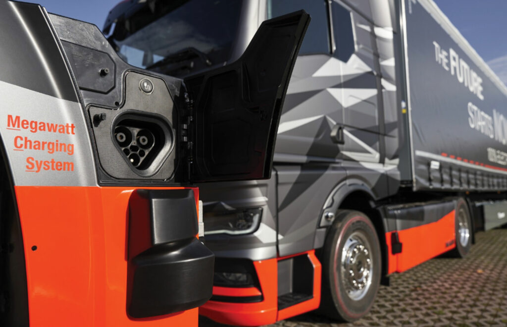
(Image courtesy of MAN)
Charging ahead
Nick Flaherty connects with the latest developments in megawatt charging systems for heavy-duty electric vehicles
In 2018, the Charging Interface Initiative (CharIN) formed the Megawatt Charging System (MCS) Task Force to develop a robust, scalable and interoperable system for fast charging of electric heavy-duty vehicles. The goal was to meet the growing demand for fast, efficient charging of high-capacity batteries in commercial heavy-duty vehicles.
To carry heavy payloads over long distances, large trucks, ships and construction equipment need larger battery packs, which means that they need fast charging and high power levels.
Fast charging with megawatts of power can reduce the battery pack requirement from 1000 to 450 kWh, saving both weight and cost. However, there are a number of engineering challenges with MCSs, ranging from the heat generated in the charger and the charging cables to the distribution of the large amounts of current at high voltages required to support simultaneous charging of many trucks. To address these problems, researchers have been working on new architectures for charging stations and pilot systems are now starting to roll out.
At the same time, the standards and interoperability tests are maturing, and the technical information for the SAE J3271 MCS was released in March 2025. This is intended for any large EV that “rolls, flies or floats,” including mining, marine, aviation, rail, agriculture and construction applications, says Ted Bohn, principal electrical engineer at the Argonne National Laboratory and chair of the SAE J3271 committee.
Larger-capacity batteries designed to support long-range and heavy load capability up to class 8 vehicles require higher charging power to keep the recharge time manageable. Existing systems based on the SAE J1772 Combined Charging System (CCS) standard can deliver up to 1000 V/500 A today for 500 kW charging, while SAE J3400 defines the North American Charging Standard (NACS) systems that can deliver up to 1000 V/900 A or 900 kW.
The DC charging Technical Information Report (TIR) for SAE J3271 for MCSs of up to 1500 V/3000 A or 4.5 MW, covers the charging equipment and control elements from the point of utility interconnection to the vehicle battery terminals.
It is estimated that up to 18 electric vehicle supply equipment (EVSE) manufacturers are developing SAE J3271 MCS-compliant EVSEs, largely as higher-power versions of their existing CCS products, says Bohn. Because the SAE J3271 standard is a TIR, none of the prototype MCS stations are compliant but they do constitute part of the validation process during development.
An early MCS–NACS dual-output functional prototype was unveiled in October 2023, with a 1800 A liquid-cooled Rema MCS charging cable.
Eight MCS charging cable and inlet manufacturers are planning to participate in coordinated communication interoperability testing of couplers and inlets at the Argonne National Laboratory.
Three iterations of the CharIN MCS task group coupler design (V1, V2, and V3) led to the final v3.2 design described in the SAE J3271 standard. Three rounds of testing were conducted at the US National Renewable Energy Laboratory (NREL) with prototype and pre-production test articles, up to 3000 A, including elevated ambient test conditions.
There are three charging configurations indicating charging power capability:
• Configuration 1 is a non-cooled connector cable and non-cooled vehicle inlet for 500 A
• Configuration 2 is a cooled connector and non-cooled vehicle inlet for 1500 A
• Configuration 3 is a cooled connector and cooled vehicle inlet/conductors for 3000 A
SAE J3271 extends the MCS standard with balanced differential signalling over twisted-pair communication wiring that differs from the CCS single-ended power line communication (PLC). The PLC technology is not part of the MCS, which will instead use CAN FD/XL communication.
Extensive work is underway to develop vehicle and EVSE communication controllers under the SAE J3271 (harmonised with IEC 61851-23-3) standard. SAE J3271 is also harmonised with IEC TS63379 and ISO 5474 standards to ensure global compatibility and future interoperability.
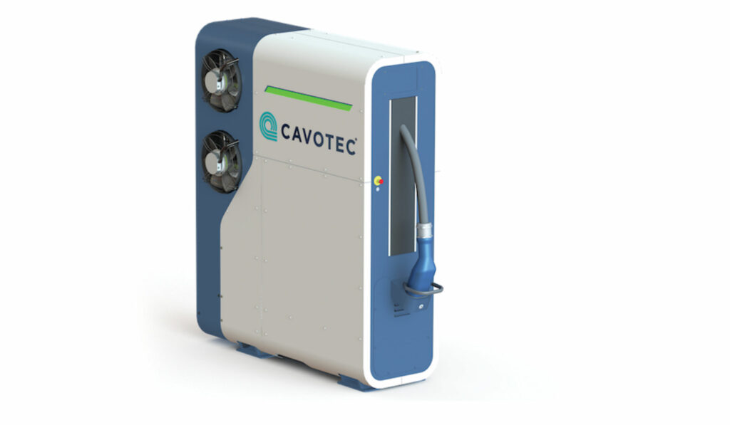
(Image courtesy of Cavotec)
Cooling
Charging at such high levels of power generates substantial heat. To keep cables lightweight and flexible, less copper is often used, which increases electrical resistance. When high currents flow through these resistive components, a significant amount of heat is produced. This excess heat can damage components, reduce efficiency and pose safety risks. Consequently, effective cooling technologies are essential for maintaining the durability and performance of a charging system.
As current levels rise, advanced cooling systems become essential for effective design, says Mathieu Chaligne, project and product manager, charging systems at connector developer Stäubli.
When choosing a cooling technology, two main factors must be considered: the cooling medium and the cable technology.
Water–glycol mixtures are commonly used in EV systems because of their efficient heat exchange and environmental safety. Oil-based coolants, while effective in state-of-the-art high-voltage static applications, require more complex infrastructure for maintenance and disposal. Stäubli favours water-based solutions for their ease of handling and overall efficiency.
The choice between direct and indirect cooling also impacts on both performance and cost.
In direct-cooled cables, the cooling fluid directly contacts the cable conductor, allowing for efficient heat exchange. This reduces the amount of copper needed and results in thinner, lighter cables. However, the fluid cools the cable conductor through an isolated tube and is never in direct contact with the copper.
For indirect cooling, the cables are cooled via an external heat exchanger. While the cables tend to be heavier, this method generates less heat, thereby allowing smaller coolers to provide the necessary cooling – ultimately reducing both operational and capital costs.
Indirect cooling is generally the more cost-effective approach because it consumes less energy and requires less cooling power.
Extensive testing to develop cooling solutions that balance performance and cost mean Stäubli is open to using both direct and indirect cooling systems with water–glycol fluid for the MCS connector. Both technologies provide reliable performance and can be tailored to meet various system requirements.
The connectors, scheduled for release in parts in mid-2025, are designed to be scalable and adaptable, ensuring compatibility with both current and future MCS infrastructure.
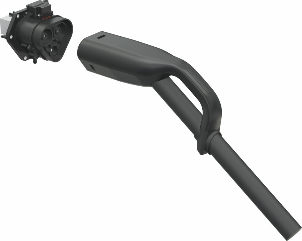
(Image courtesy of Stäubli)
Thermal compatibility
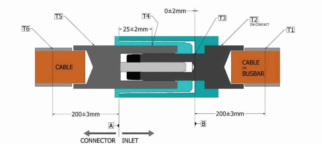
The connectors also need to work with the inlets, and these have been tested at the NREL using a thermal interoperability test bench.
The connector, consisting of a cable approximately 2 m in length provided by the participant and terminated at one end with an MCS connector with socket terminals and terminated at the other end with electrical connection lugs, was bolted to an NREL-provided bus bar and instrumented with up to 14 thermocouples. Transducers were also provided to enable data collection from optional participant-provided Pt1000 resistance temperature detectors.
Before being placed under test, the connector would be mated to a participant-provided inlet with shorted terminals or electrical connection lugs that would then be bolted to an NREL-provided bus bar, with a cable approximately 0.75 m long. The inlet was instrumented with up to 13 thermocouples to test the thermal compatibility.
For future MCS connector designs to be evaluated more effectively by industry, a reference device has been developed by the IEC PT63379 working group to serve as a standard inlet that can provide a baseline minimally acceptable thermal performance.
Reference device evaluations consisted of two types of characterisations. During the first characterisation, connectors were run at either 1500 or 3000 A, depending on their current rating, until the devices reached steady state, with cooling levels similar to those used in the interoperability evaluations.
The second type of characterisation, performed with only certain connectors, consisted of running the device at rated current, then adjusting the cooling level until the reference inlet pin temperatures reached a target level of 100 C (at 40 C ambient) or 85 C (at 25 C ambient).
Each evaluation was performed at 40 C, and repeated at 25 C, to help evaluate the necessity and performance implications of the 40 C ambient temperature test requirement.
(Image courtesy of NREL)
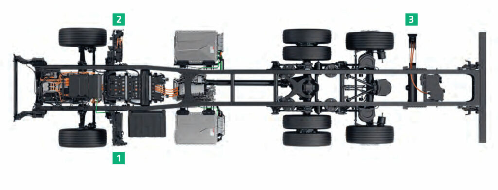
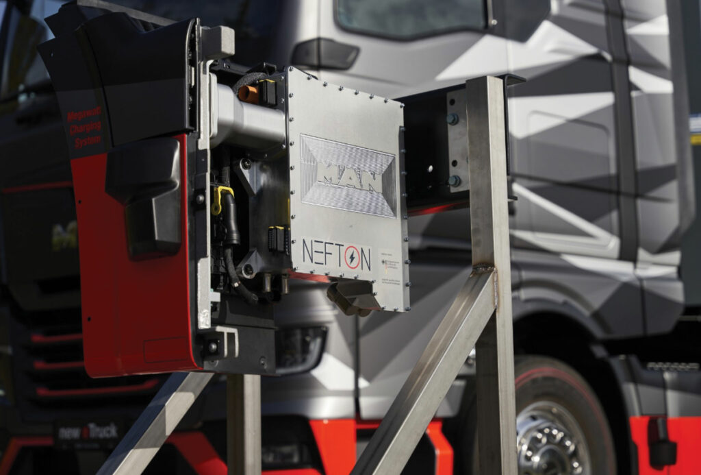
NEFTON project
To cover long distances daily, trucks require up to 1000 kWh of energy. Batteries of this size represent a considerable financial investment as well as a considerable weight.
However, megawatt charging with the new MCS standard can reduce the required size to 450 kWh, significantly increasing the cost-effectiveness and sustainability of battery electric trucks.
This reduction in battery size is the core idea of the NEFTON project in Germany, which has developed a prototype vehicle and a prototype charging station that enable charging with up to 1000 kW in 30 minutes, well within the legally prescribed breaks for drivers.
On the vehicle side, various components interact to support megawatt charging. A modular battery concept is necessary to meet user requirements because larger battery capacities reduce the charging rate of the cells and thus enable higher charging power. Despite the rise in temperature in the battery system due to charging losses, thermal management enables largely constant charging over most of the charging process. Optimised cooling and an efficient charging system are crucial for reducing operating costs and maximising vehicle availability while ensuring flexibility and user orientation.
The charging infrastructure in the NEFTON project was implemented in a modular way to enable fast and flexible installation. The inner intelligence of the infrastructure lies in the interconnection of power electronics modules via a switching matrix, and the combination of modular bidirectional power electronics with highly efficient unidirectional power electronics. This switching matrix enables the targeted allocation of power units to several charging points as required, as well as the operation of individual modules in optimum power ranges. A central controller controls the energy flows from a grid connection or a second life stationary storage system, thus reducing the peak load on the power grid.
At the same time, a dense and powerful public charging network is required for long-distance transport applications. In distribution transport, on the other hand, megawatt charging is often not required because intelligent fleet and charging management can significantly reduce energy and grid costs at the depot.
These high currents need high-performance protection from a contactor that can quickly and reliably isolate the truck from the high currents and voltages.
“Looking at the developments in early 2024, we decided that it makes sense for us to go in this direction, to develop a contactor to support this trend to MCSs, and we are experts in switching high voltages and high current, so this is the logical next step,” says Guenther Rott, who is responsible for global product management and application engineering at Schaltbau, which was involved in the NEFTON project with MAN.
“It is interesting for us and we are in concrete projects with German truck makers,” he says. “We also work on both sides, both the truck or eBus and on the charging side.”
The company worked with MAN to develop optimised 1000 A charging with a 3000 A concept for the 10 prototype trucks developed last year with the first live MCS and new cooling concepts.
The most challenging point is on the infrastructure side because an intelligent system is needed for charging 10 or 20 trucks at the same time on the highway. This started off with the C800 contactor that was developed for high volume e-mobility designs.
The C800 series is used in the truck’s power distribution unit (PDU) for battery emergency cases, in which the contactor safely disconnects the current to safeguard the vehicle, driver and freight. The bidirectional contactor is notable for its high current carrying capacity and its high energy efficiency, making it perfectly suited to switch power in a small space and in applications with energy recovery, such as the PDU of modern e-vehicles.
“We used two C800 contactors initially up to 1 kA in parallel, but this is not the final target. Phase two of the development is the C320 that under specific conditions can handle up to 2 kA depending on the busbars that are used and what cooling is installed,” Rott says. “We have prepared some samples and they are in testing with a truck manufacturer.”
“What we are working on is a product that can cover up to 3000 A, the C330. The key point is always the thermal balance. This is an issue of the physics because the hotspot is always near the contact, so the trick is to have really low contact resistance to reduce the power loss as much as possible in this critical area, and there we have a special concept,” he continues.
“This integrates two functional groups,” says Rott. “One functional group will do the hot switching and the load, while a separate group is responsible for keeping the contact resistance over the lifetime of the product at a suitable low level. It’s a combination of all our experience of the last 50 years of r&d in high-current contacts. This comes from the design of the inner bus bars and the question of the contact materials used, and the power of the coil system and self-cleaning of the contact system.”
There are two different versions for trucks and stationary chargers. “The current you need in the truck you need in the charger, so the products are corresponding but not the same type,” he says.
“For stationary usage, you have no shock and vibration requirements, so there are some areas where you can specify down a little bit but the technique is the same. For a contactor that can handle up to 3 kA, there must be a lot of powerful busbars, and this means a lot of masses integrated which has an impact on the shock and vibration, as well as other severe environmental conditions such as high temperatures,” Rott continues.
“The good thing is that in charging mode, the truck is not driving but the product has to survive in the non-active use state when not charging, so it’s different from a traction contactor in a vehicle.
“For other applications, in the vehicle we also have special contactors with integrated locking systems and this avoids moving to an uncontrolled position. But this is not used in the megawatt charger because it is not necessary. There is no additional mechanical interlock; it is software- and measurement-based by the battery management system.”
The MCS specification details the position of the charger on a truck to make it accessible, but the positioning of the contactor is not yet decided.
“Typically, the contactor will be close to the connector in the truck because you also have to take care of the losses in the battery system. Charging cables are 3 to 5 m, to give room to connect different trucks, but in the charging system, we have active cooling systems so it is possible to keep the temperature at the necessary level,” says Rott.
The MCS standard is to be further tested in an extension of the NEFTON project. Charging currents of 3000 A will be tested, allowing an electric truck to be fully charged in 15 minutes. For NEFTON-3000, the Technical University of Munich, MAN Truck & Bus and the Deggendorf Institute of Technology are developing concepts with charging capacities in the range of 3 MW, which will also be tested on test rigs at Fraunhofer Institute for Solar Energy Systems.
(Image courtesy of NEFTON)
Multiport charging station
In the US, the Oak Ridge National Laboratory (ORNL) is working on the requirements for charging stations that have to handle multiple trucks simultaneously.
The researchers at ORNL have designed architecture, software and control strategies for a futuristic EV truck stop that can draw megawatts of power.
The station’s design uses solar arrays and batteries, which generate and store enough power to handle the unpredictable load swings from recharging these large power plants on wheels. The software manages the system to draw a steady, predictable flow of power from the grid. The team fine-tuned the complex control hierarchy using real-time simulation, then verified their results with electronics in the lab.
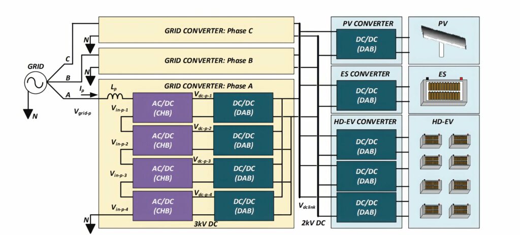
The developed megawatt-scale charging system/station supports power levels of 10–15 MW for vehicles ranging from heavy- to medium- and light-duty trucks. The multiport power conversion system is designed to interface and coordinate various assets and loads including grid, battery storage, solar cells and the vehicles themselves.
Each multiport is designed to handle 1–5 MW with a charger dedicated to controlling the power delivery to the truck.
Multiple multiports can be interconnected through the AC distribution network creating large networks of chargers for supporting the electrification of these higher-power vehicles. This will require station controllers that can optimise and dispatch the power to the multiports without significantly impacting the electric grid interconnection.
The multiport charger was designed to support three high-power 1.2 MW chargers, each with a single MCS connector or three 400 kW CCS fast chargers running at 1000 V.
The 400 kW charging ports are composed of dual-active bridge (DAB) converter systems that can control the DC link interconnection to the truck. However, this will require that each heavy-duty EV incorporates three different charging ports to increase charging capability and provide the ability to potentially sectionalise the battery system.
The grid-tied interface is a 13.8 kV system consisting of cascaded H-bridge (CHB) modules tied to dual-active bridge (DAB) modules through a 12 kV DC link. Four of these CHB-DAB modules per phase are connected in series to meet the voltage requirements and the power handling capability of 1.2 MW per phase.
Together, the 12 CHB–DAB modules are connected in parallel at the output port to provide the 2 kV intermediate DC bus at 3.6 MW for supporting simultaneous charging of three trucks.
Both the energy storage and the photovoltaic power electronics interfaces are single 400 kW DABs connected to their respective resources. These can easily be scaled to higher power systems depending on the need for supporting the multiport or electric grid interconnection.
The systems have been tested on the controller hardware-in-the-loop testbeds at ORNL to validate both the software architecture and the station operation during transient and steady-state conditions.
The MCS architecture and operation has been validated for two different scenarios, including simultaneous charging of high-power vehicles, and future work will look at different options and profile development for charging.
“The next phase is looking at how to coordinate multiple stations in a network along the interstate,” says ORNL researcher Radha Krishna Moorthy.
(Image courtesy of Schaltbau)
Mixed connections
Kempower is taking a different approach to mix megawatt and CCS2 connector systems for certain truck charging scenarios, such as on-the-move and destination charging, which can require short bursts of high power.
It has started pilot deliveries of the MCS from its European factories. This system can deliver up to 1.2 MW of power and 1500 A of current for long-haul electric trucks and other energy-intensive vehicles.
The Mega Satellite System is designed to work with current MCS and CCS2 DC charging standards, and is ready for future megawatt charging standards. The system can simultaneously charge two trucks using CCS2 connectors, delivering 700 A/560 kW to each truck at the same time. The MCS and CCS outputs can be used in the same system for maximal flexibility, and the unused power can be distributed among several outputs through dynamic power sharing.
This allows the current CCS2 power levels for heavy-duty vehicles to be increased in the short term to enable the market transition toward full MCS adoption in the coming years.
The first implementation of this is at Virta’s charging station at Linköping in Sweden. The charging system has four CCS2 charging spots with Kempower’s liquid-cooled charging satellites with power output of up to 400 kW; the addition of megawatt charging increased the power delivery to 1.2 MW.
Similarly, Siemens has used its existing power designs for a prototype of its SICHARGE MCS. This uses multiple SICHARGE UC150 power cabinets and a high-power switching matrix with a customized MCS dispenser.
The switching matrix is the central element in the MCS, bundling the output power of the charging stations and, depending on the requirement, directing the power to the MCS dispenser. Batteries commonly used in electric trucks could be charged from 20% to 80% in approximately 30 minutes at a suitable charging station with an output of around 1 MW.
(Image courtesy of ORNL)
Conclusion
Megawatt charging is maturing with the SAE J3271 standard, new communication techniques and thermal testing for the connectors to ensure interoperability at 1500 A and even up to 3000 A. Schemes such as the NEFTON project with its 10 prototype vehicles are showing how MCS can be integrated into trucks for fast charging.
The technology is evolving with a mixture of CCS and MCS connector systems, leading to new multiport charging system designs that can support multiple vehicles using MCS connectors. The move to a 3000 A system is going to challenge the thermal management of the connectors and cables further in the drive to provide faster charging for existing vehicles and support even larger battery packs in the future for more practical long-range operation, whether on or off-road or on the water.
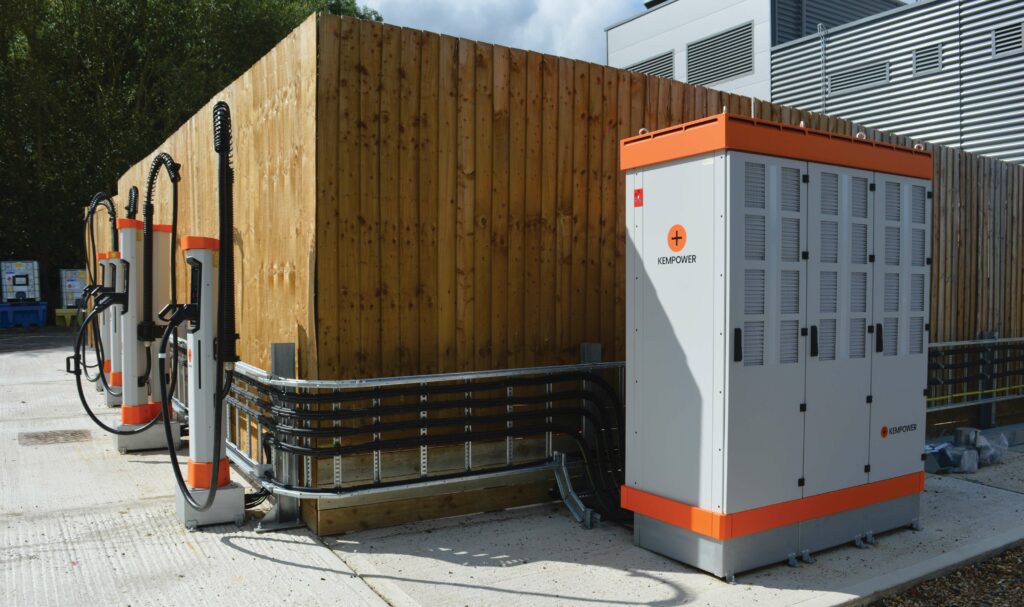
(Image courtesy of Kempower)
Click here to read the latest issue of E-Mobility Engineering.
ONLINE PARTNERS
