


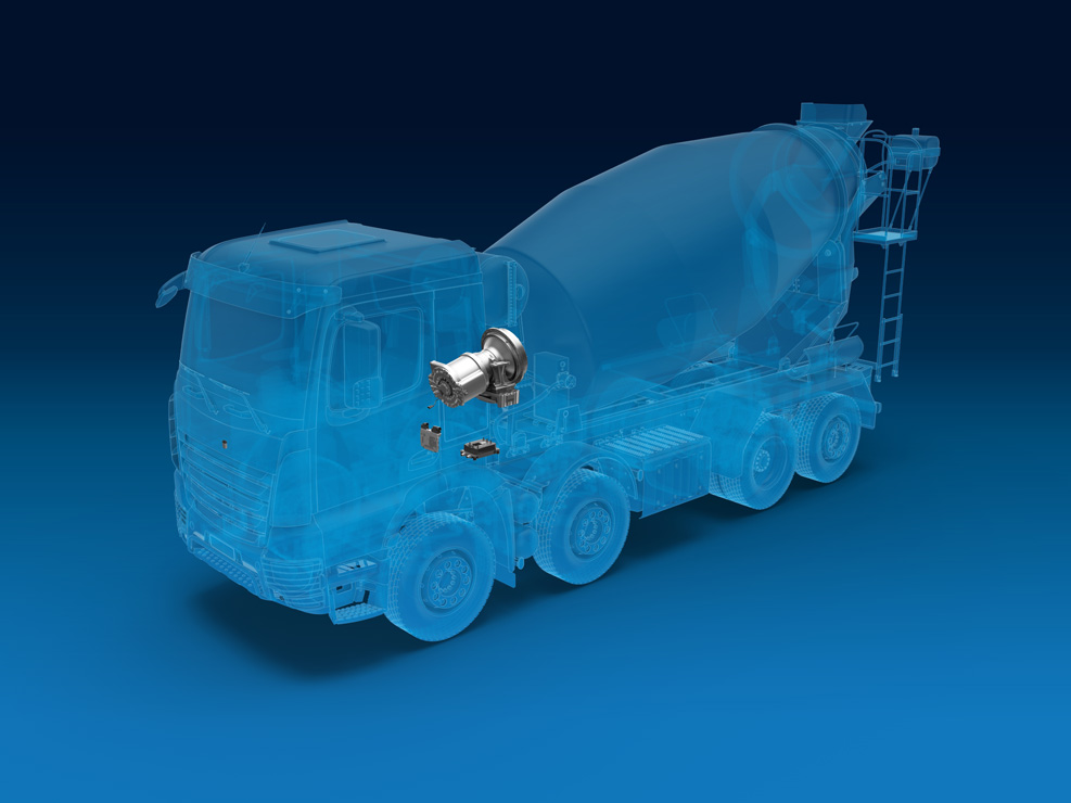
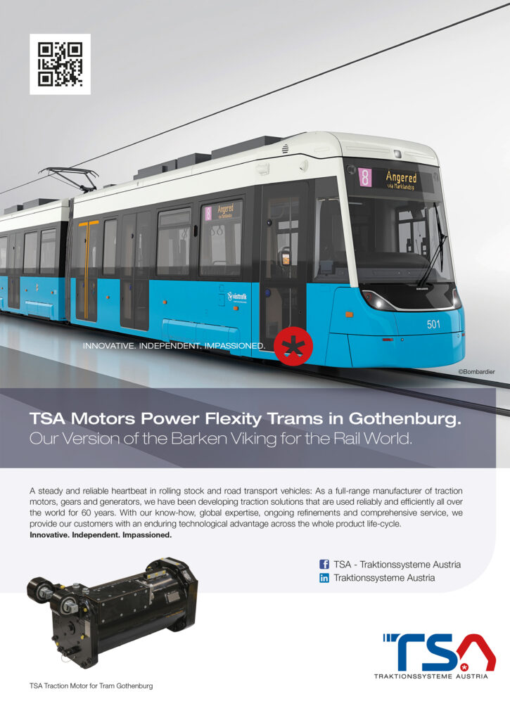
Liebherr ETM Series
(Courtesy of ZF)
Developing these all-electric cement mixer trucks has meant blending the bespoke with the off-the-shelf. Rory Jackson reports…
The right mix
The conventional cement truck is a diesel-powered vehicle that spends much of each working day at a standstill. However, whether it is having concrete ingredients fed into its mixing drum, dispensing the mixture at a construction site or merely waiting to do one or the other, its drum mixer will almost always be turning.
Even if the truck is stationary, its diesel engine must continue idling in order to drive the drum from the ICE’s power take-off (PTO). The excessive amount of fuel needed to run the ICE relative to productivity – 3-6 litres of diesel per hour while idling – led customers of construction machinery company Liebherr-Mischtechnik (headquartered in Bad Schussenried, Germany) to first request an electrically driven cement truck mixer in 2017.
Silvan Gadner, Liebherr’s product manager for truck mixers, recalls, “Back then, our r&d team had been looking into how electrification could improve our products, but to accomplish this quite specialised project, we began working closely with ZF, who have a lot of experience in electrifying heavy commercial truck powertrains. They became our key partner on developing an electric drum mixer, providing a number of critical parts and design consultations during the process.”
As Liebherr quickly realised, electrifying the mixer would also greatly save on construction fleet maintenance costs. By replacing the hydraulic drive with an electric motor and transmission system, and reducing the ICE’s daily runtime (which remains in place for PHEV versions of the truck), the tally of moving parts – and hence failure points – in each truck is significantly reduced.
Oil consumption is also reduced to the quantities needed only for routine lubrication of the electric powertrain.
In addition, Liebherr predicts that demand for electric versions in city projects can only grow in line with rising global populations and urbanisation.
Reducing their emissions and noise will therefore be increasingly critical to their use in the future, especially as more major cities place partial restrictions or outright bans on where ICEs can be used.
It is with these long-term trends in mind that Liebherr has developed its ETM (Electrically-driven Truck Mixer) Series of mixer drums, for integration onto end-users’ existing trucks or trailers along with the supporting electric components.
The ETM drums come in a range of capacities, from 7 to 12 m3, for carrying compacted mixed concretes (specifically, types F1, F2, F3, F4 and F5). They are driven by an electric motor, which produces peak power of 125 kW, or 60 kW as a maximum continuous output to turn the drum at 14 rpm. Data from field tests has found only very small differences in power requirements between the different drum sizes.
(Courtesy of ZF)
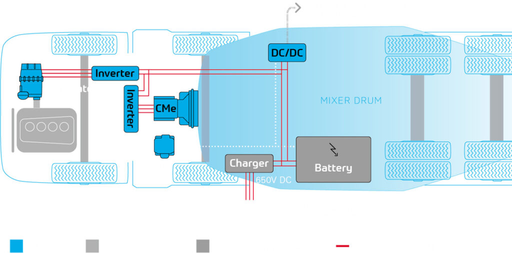
The ETM drums have mostly been supplied as turnkey systems to customers in Europe, for use on their existing truck cabs and drive systems, and until recently they were all produced as partial series hybrids. This entailed packaging a 32 kWh battery pack (with a 650 V DC supply), a 22 kW onboard charger, and a generator from Parker (flanged to the PTO of the existing ICE via a cardan shaft with two universal joints) along with the ETM drum, motor and transmission onto an articulated trailer behind the truck cab.
The PHEV trucks commute between plants and job sites using their diesel ICEs for traction, shutting them off while stationary at either location and running their mixing drums on battery power. The battery packs can be recharged by running the generator while driving or by plugging them into a charging point or mobile generator while stationary.
“Since cement trucks are generally stationary throughout the day, that series PHEV architecture greatly reduces emissions, even while retaining diesel-powered traction,” Gadner notes. “Overall, our customers have reported savings of 25-30% in diesel consumption, with the amount in CO2 emissions being the same.”
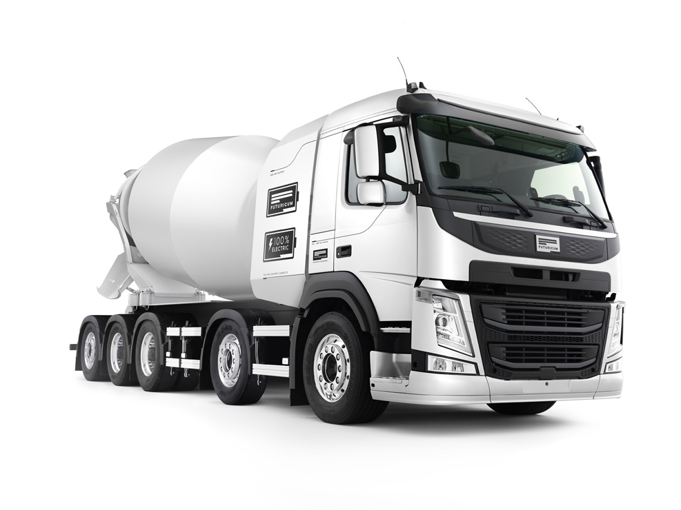
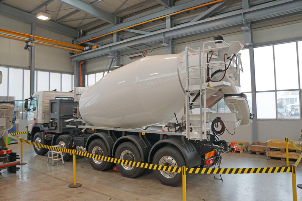
He adds, however, that Liebherr had always intended the ETM to eventually form part of a fully electric solution. That vision is now being realised in the form of a 40 t all-electric cement truck that combines Liebherr’s 12 m3 ETM with a truck chassis from EV systems integration and r&d company Designwerk. It has been prototyped and is now undergoing trials as the world’s first zero-emissions truck of its kind.
The ETM drum drive
The ETM has been engineered by Liebherr-Mischtechnik and ZF according to a few key design targets.
In addition to improving over the average commercially available mixers in terms of energy efficiency, noise and productivity, the total cost of ownership had to be much lower to make it worthwhile for construction firms to acquire and integrate the mixers (and associated control and charging systems) onto their existing trailers and trucks.
To achieve the cost goal, the two companies sought to build the ETMs using electric motors and inverters from ZF’s existing production lines. A bespoke solution would have been far more costly to develop, and much more difficult to troubleshoot over its lifespan compared with more tried-and-tested components.
As mentioned, all the above improvements can be achieved to an extent by replacing the conventional cement mixer’s hydraulic pump – flanged to the ICE’s PTO as standard – with an electrical generator, and the high-pressure hydraulic drive with an electric motor.
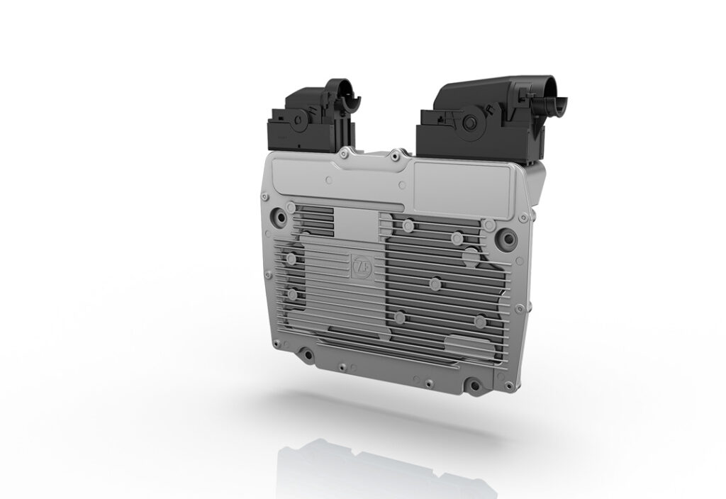
The new electrical drum drive was therefore assembled by taking the e-motor from ZF’s AxTrax-AVE130 system – an electric portal axle originally developed for buses – and installing it into ZF’s patented CML 12 drum drive and transmission system from the company’s Ecomix II series of concrete mixer products (in place of that system’s standard hydraulic motor).
The e-motor itself is a three-phase AC induction (squirrel cage) machine. The system is liquid-cooled, has a maximum speed of 11,000 rpm and a peak torque output of 485 Nm.
Although synchronous motors operate with higher full-load efficiency, an asynchronous motor was chosen owing to its comparative simplicity of design, and therefore lower manufacturing cost, relative to permanent magnet machines. They are also generally regarded as less sensitive (and so more robust) to changes or extremes of temperature, making them ideal for use in heavy, commercial urban vehicles.
In addition to having the right motor, the overall transmission had to ensure enough output torque for sufficient mixing of the densest classes of concrete, in line with industry regulations DIN EN 206-1 and DIN 1045-2. For that, 64,000 Nm was needed at the drum flange.
To enable enough continuous rotating force, two extra gear ratios were added between the e-motor and the CML 12, for a total gear ratio of 308:1, achieved via a three-stage planetary gear.
(Courtesy of ZF)
The standard CML Series hydraulic drive in Liebherr’s conventional mixer drum typically uses an axial piston pump to drive a radial piston hydraulic motor, with a single-stage planetary gear transmission connecting the motor to the drum.
Gadner states that on average the electrical system adds roughly 750 kg to the total weight of the cement truck (mostly attributable to the battery packs). While this extra weight might imply an increase fuel costs, it is important to remember that the trucks spend most of their daily operations standing still, so an increase in kerb weight does not increase running costs; as stated, keeping the ICE switched off when it isn’t needed keeps them down.
There is no official precise figure for the lifespan of the hybrid-electric powertrain, but Liebherr is confident that it will last at least as long as the hydraulic drivetrain. The battery will again be the main limiting factor, as different end users will use its capacity differently.
ETM voltage architecture
The mixer’s electrical network has been constructed around a 650 V architecture, partially out of a desire for low line losses but also because Liebherr and ZF identified this figure as an emerging standard among high voltage commercial EVs.
In the PHEV arrangement, as the generator runs off of the customer’s ICE behind the truck cab, its AC power is rectified into 650 V DC primarily for charging the battery, which also has a cable connecting it to the 22 kW onboard charger for recharging when the truck is stationary.
The standard ETM PHEV battery pack contains 32 kWh and is assembled and supplied by Kreisel using 18650 cylindrical NMC cells. Also, the batteries are thermally managed using that company’s patented liquid circulation technique.
(Courtesy of Liebherr)
This approach consists of sealing a fluid-tight space around the midsections of the cell jackets, using two upper and lower ‘plates’ designed with a number of ring-shaped hollows equal to the number and arrangement of cells, to slot tightly onto their cylindrical form factors.
Water or water-glycol is then pumped through the space, ensuring no two cells’ temperatures differ by more than 5 C, and allowing the temperatures of all the cells to be quickly and uniformly altered by the onboard heat exchangers.
The battery supplies power to an inverter for powering and controlling the drum drive. It also feeds a DC-DC converter that steps the voltage down to 24 V, as is standard in commercial vehicle systems, for the HVAC and other cabin electronics as well as the active thermal management systems and control systems.
The ETM’s primary control system is the eDCU (electric Drum Control Unit), which is based on ZF’s EC3 gearbox control unit and which monitors data and processes commands between the cabin and the powertrain.
The eDCU’s hardware is unchanged from that in the EC3. It is based on a Freescale MPC5644A 32-bit microcontroller with 4 Mbytes of fl ash memory, three CAN ports, three serial ports and 192 kbytes of SRAM, in an IP69K-rated enclosure.
All information is transmitted via CAN (as per the SAE J1939 standard) and includes all the signal inputs from the motor inverter, generator, DC-DC converters, onboard charger, human-machine interfaces, the diesel engine’s ECU and the BMS. That in turn manages the active balancing of individual cell voltages and capacities during recharge and discharge periods, as well as a range of other standard BMS functions.
Systems integration and safety
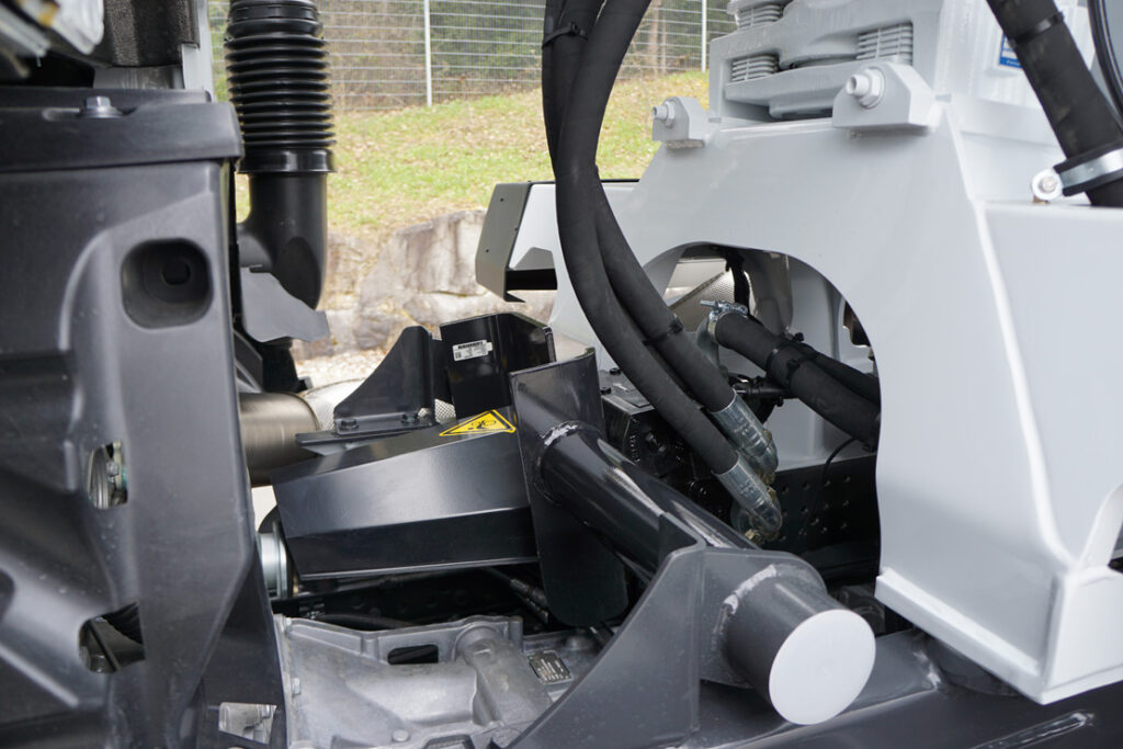
The coolant pump and heat exchangers are typically installed next to the electric drum drive – as they would often be with a conventional drum drive.
“We have two cooling circuits in the PHEV ETM,” Gadner says. “One is for the battery, because in operation NMC needs to be capped between temperatures of 20-40 C to maximise its lifespan.
“The other is for the power electronics and the drum’s e-motor, because those systems need to be brought down from peak temperatures of 100 C during extreme loads.
“For the hydraulic drive though it’s one cooling circuit with a constant-speed fan-based oil cooler. And in the electric drive there are two fan coolers – one for each circuit – with variable speed fans to increase or reduce the degree of cooling depending on peaks or troughs.”
The battery is typically mounted at the front of the trailer, in a specially designed frame to protect it against mechanical stress. This position enables the battery pack to sit between the generator and the drum drive (no more than 1 m from each) to minimise the lengths of HV cable running between.
Given the quantities of solid and fluid materials that the cement truck has to handle during operations, each of their enclosures is designed to IP6K9K requirements for protection against any ingress from dust or water.
As well as component safety, human safety was prioritised from the outset, with a joint risk and hazard analysis undertaken by Liebherr and ZF at the start of the process, and all relevant EV safety standards applied throughout development. For example, all the electrical connectors have been manufactured with pilot contacts, which are designed to shut down system circuits before contact or arcing can occur.
Software architecture
The vehicle and battery management software systems were developed using a simulated model of the ETM. Physical characteristics and dynamics were modelled in Dymola, and control algorithms were constructed and implemented through MATLAB Simulink.
The eDCU’s control software was written in C++, and as well as modelling its performance in Dymola, the engineers also tested and verified it throughout development using SoftCar, ZF’s testing environment designed for accurate simulations of CAN bus networks.
The EC3 unit came ready with the necessary I/Os and bus behaviours, with Liebherr’s and ZF’s software engineers just needing to write the control software followed by a signal abstraction layer for ensuring that all commands in the application layer relating to software functions scale as appropriate and arrive with errors having already been handled.
Critical functions to be processed through the eDCU include raising, lowering and speed control of the drum. The last of these is particularly important as it contributes directly to how effectively specific concretes are mixed.
PHEV charging
The eDCU monitors and controls the rate at which the generator charges the battery, up to a peak of 50 kW.
This is a critical function to balance, as it takes power from the truck engine that may be needed for driving. However, charging while driving is the best way of integrating the PHEV mixer into construction workers’ daily routines without changing any of their operating procedures.
Alternatively, in driving conditions such as downward slopes or when braking, the forward motion of the truck wheels is transferred through the axle, back to the engine’s crank and PTO, and thus to the generator, recuperating battery energy.
Assuming standard concretes are being mixed, the eDCU can command the generator to keep the battery at a reasonably constant state of charge (SoC) or linear rate of discharge over the course of the working day, after which a slow overnight plug-in charge can be applied to replenish the depth of discharge.
(Courtesy of Liebherr)
As the infrastructure for charging points and high-voltage power outlets remains inconsistent across most of Europe, Liebherr and ZF recommend investing in stationary or mobile charging stations near the plant’s truck loading or parking bays.
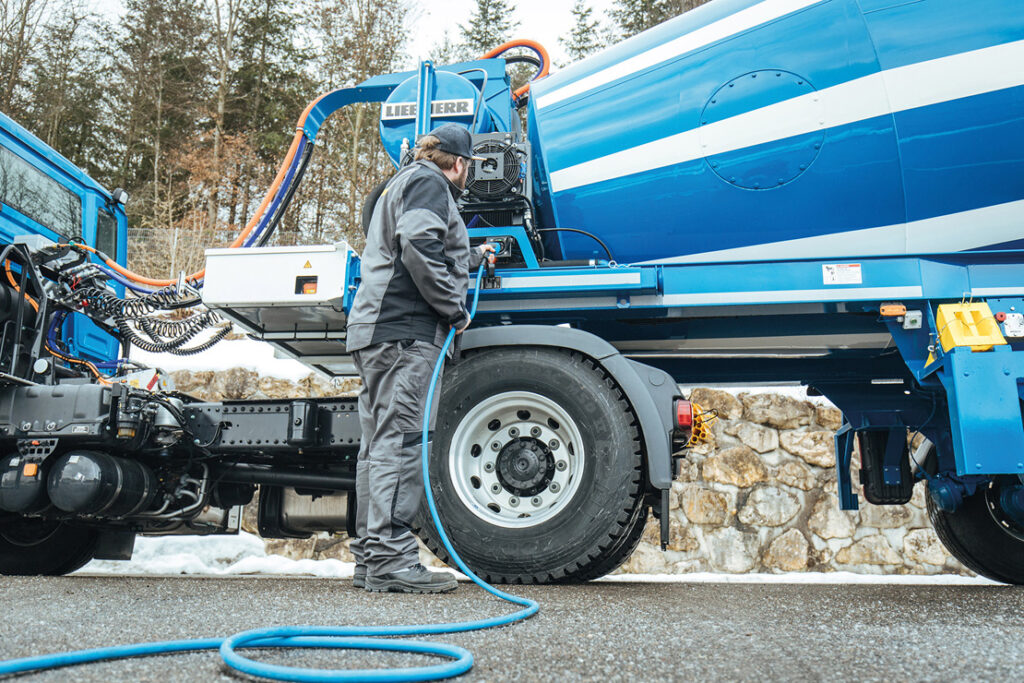
This is especially important, as some mixer trucks will spend 10-minute periods each day being reloaded with concrete and water at batching plants, which typically already have three-phase 400 V AC, 32 A connections ready for use in opportunity charging. Ten minutes on this type of supply will restore around 3.5 kWh of battery energy, although Liebherr and ZF plan to offer DC fast charging at a later date.
A CCS Type 2 input socket is fitted to the trailer as standard, on the same side as an input for water for the mixer (although they are separated for safe mating and disconnection) and it has a status LED for indicating successful recharging.
If the energy management system detects an insufficient SoC (possibly owing to a large amount of a heavy type of concrete combined with a high load from elsewhere), it will automatically activate or accelerate the truck engine so that the generator can perform a booster function, offsetting both the load peak and the low battery charge.
From PHEV to all-electric
As mentioned, Liebherr had anticipated from the outset that the ETM system would eventually be used in a fully-electric solution; however the company chose to wait for customer requests before investing r&d in a battery EV architecture.
“The first customer interested in an all electric cement mixer approached us in autumn 2019,” Gadner recalls. “Soon after, we started the actual development, and the first fully electric truck with a 12 m3 ETM is ready for certification trials in driving and mixing operations.”
Designwerk has been the primary partner for developing, assembling and supplying the electric truck chassis and powertrain. The company is divided into Designwerk Technologies, which focuses on r&d, and Designwerk Products, which works largely on commercialising the former’s findings and developments.
Based on experiences of previous electric powertrain projects, Designwerk has productionised its electric truck chassis and powertrains as the Futuricum e-truck, which forms the basis of Liebherr’s all-electric cement truck.
The Futuricum uses a four-axle Volvo truck chassis as its base frame, partly owing to the wide acceptance of the latter’s quality standards among fleet operators.
(Courtesy of Designwerk)
“Although the cement truck is the first five-axle truck Designwerk have worked with, its development has still proceeded quickly. It’s only slightly different from their standard integration processes,” Gadner adds.
Even more important, Volvo agreed to give Designwerk’s engineers access to its CAN bus information – a critical requirement for integrating, controlling and optimising electric drive components into the chassis.
As well as enabling the interfaces between Designwerk’s CAN communication nodes to be defined, and making vital CAN protocol data available to them, Volvo removes drivetrain components from its chassis to make space for the electrical machinery and associated mechanical and connectivity systems.
Volvo also provides general development support and consultation to Designwerk on the project, as it has with each previous Futuricum e-truck.
Each truck is subjected to a number of tests, including brake tests, steering tests, EMC testing and low-voltage compliance testing, before being delivered.
Futuricum drivetrain
Powertrain components have been chosen with ease of assembly, operation and maintenance in mind. Modularity and redundancy are designed in throughout the e-truck’s architecture, with clearly defined (and easily accessible) mechanical and electrical interfaces for every part, as well as secondary units and connections in most places.
The balance and arrangement of parts in the drivetrain serves as the biggest example of this.
Where a conventional 12- to 18-wheel truck would have its diesel engine in the forward-centre of its chassis, Designwerk has positioned the electric drive.
This consists of four electric motors, all connected to a central single-speed gearbox and driveshaft. The e-truck also has four inverters (one controlling each motor), dual battery packs and onboard chargers.
This arrangement ensures that the cement truck can continue driving (albeit at reduced speed and power) even if one or two components fail or are shut down owing to a possible defect.
The failure of a single large traction motor, by contrast, would immediately strand the cement truck in traffic and potentially cost its end-user thousands of euros per hour in lost productivity.
“We’ve also found that manufacturing four smaller e-motors is less expensive than one big one, and results in a lighter overall drivetrain, assuming the same power output for both scenarios,” says Duga Hoti, product manager for e-trucks at Designwerk Products.
“Smaller motors are also manufactured in higher quantities, and thus have more secure supply chains than very large e-motors.”
Overall, the electric drive package weighs around 450 kg, roughly one-third of the equivalent diesel drivetrain.
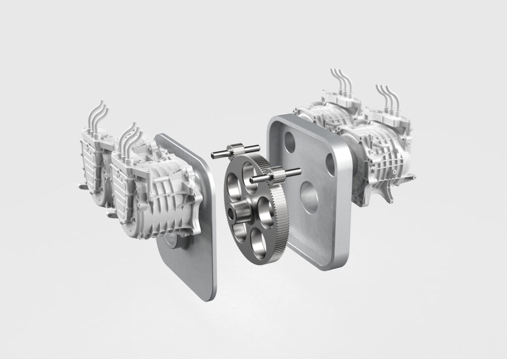
The first step in creating the electric drivetrain was to design a single-speed gearbox, as gearshifts could reduce overall traction efficiency and interrupt thrust and acceleration. Combined in an aluminium housing, the arrangement is also lighter than a conventional manual gearbox.
The resulting design positions the four motors as two opposing pairs and connects them in parallel for consistent synchronised output, with each pair driving a single straight-cut gear between them.
The two gears together drive a larger central gear on the cardan shaft. This arrangement serves to minimise the number of parts needed in the gearbox, and provides a 6.4:1 reduction ratio between the motors and driveshaft, with a further reduction of 4.8:1 between the driveshaft and the transmission axle.
Designwerk has trialled its gearbox through test runs to eliminate excess heat being generated from gear backlash, as well as excess noise.
While the gear housing is milled from a high-strength aluminium block, the gears are made of tempered gear steel and are case hardened. Spindle ball bearings are used on the driveshaft to withstand high-speed loads and ensure a service life of at least 500,000 km.
(Courtesy of Designwerk)
Designwerk has opted to use four 125 kW AC induction machines, for a total rating of 500 kW continuous power for up to 5 minutes in the Liebherr truck.
These were regarded as being the more energy-efficient choice for the drive and load cycles of a cement truck (particularly its low speeds and start-stop patterns) than permanent magnet motors, as well as being more widely available and cost-effective.
“These motors are actually capable of a collective 800 kW, but Volvo has told us that the rear axle can be destroyed by too much output power on the driveshaft, so we limit them through our vehicle control unit [VCU],” adds Simon Thalmann, engineer at Designwerk Technologies.
Although Designwerk can select motors to optimise for different e-trucks in different cities and municipalities, the standard 125 kW motor is a 52 kg system measuring 383 x 359 x 280 mm, with an energy-efficiency rating of 96%. Its top speed is 11,400 rpm and it can produce up to 250 Nm of torque, with standard continuous torque of 180 Nm at 4800 rpm for 90 kW of continuous power output.
E-truck power distribution
At the centre of the Liebherr truck’s voltage architecture sit two high voltage distribution units (HVDUs), assigned as the ‘power’ and ‘auxiliary’ HVDUs.
The two battery packs each connect to the power HVDU on two nominal 350 V, 50 A lines for redundancy. The power HVDU in turn connects to each of the four motor inverters, two onboard chargers and the auxiliary HVDU.
The auxiliary unit supplies power to all the other onboard electric components, including the heater, the air conditioning and air brakes compressors, as well as the 24 V DC-DC for the cabin and control electronics.
As with Designwerk’s previous e-truck projects, the Liebherr truck’s battery and high-voltage architecture use a nominal 360-400 V DC network, even though like Liebherr it acknowledges that 650 V DC will become the standard among large commercial EVs.
The 400 V figure was chosen owing to market availability, and continues to be seen as optimal by Liebherr. The company has found that the 320- 450 V region has the highest volumes of readily available, well-designed and cost-effective components for all electric powertrains.
Somewhat surprisingly, Liebherr found in January 2020 that the 400 V supply fed into the mixer drum system seamlessly. The 650 V-rated ZF motor was tested in Liebherr’s Dymola simulations and safely produced the required 60 kW of maximum continuous power – and the 64,000 Nm of continuous cement mixing torque – on a 400 V supply, without needing a DC-DC converter to step up the input voltage supplied to the ZF inverter.
The voltage network has been designed in accordance with current automotive standards for comms and safety, with Designwerk’s own additions where appropriate. All HV cables are shielded and clearly marked in orange insulation jackets, and most of their connectors are removable plug-in types, chosen to accelerate initial assembly of the powertrains as well as reduce maintenance needs to minimise downtime.
Also, all the CAN bus lines are accessible from the cabin using a local data logger and telemetry interface for easy remote diagnostics.
EV batteries
Although Designwerk’s previous e-trucks typically mounted their battery packs between the first and second axles, for the cement truck EV it followed Liebherr and ZF’s model of installing them near the front of the trailer, behind the cab, to balance their weight against the mixer and concrete payload.
For ease of integration and programming for the powertrain (and to exploit tried and proven e-truck traction battery architectures), the truck mixer uses battery packs assembled by Designwerk subsidiary Batteriewerk.
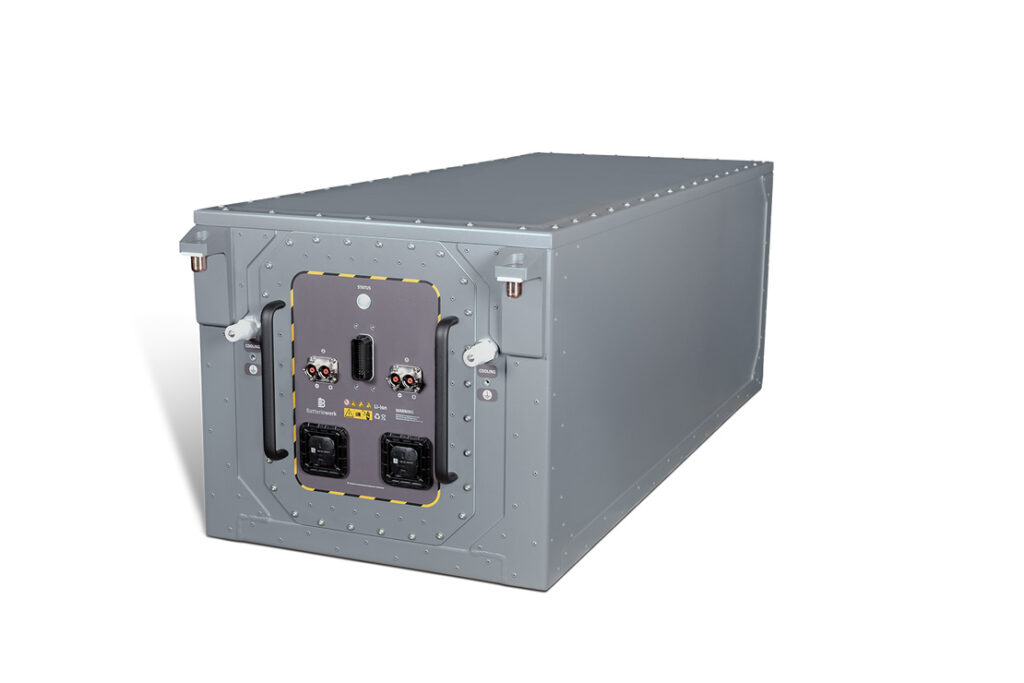
(Courtesy of Designwerk)
Two packs, weighing 1,135 kg each and containing 170 kWh for a cumulative 340 kWh, are installed between the cab and the mixer drive. “This amount of energy storage strikes the right balance between being able to cover all materials transporting and mixing duties over the course of a day, while also ensuring they can be fully AC-recharged overnight,” Thalmann says.
Each is assembled using 94 Ah cells, in modules supplied by BMW. These, like the Kreisel batteries on the PHEV’s architecture, are NMC-based and housed in an IP67-rated aluminium enclosure.
Although Batteriewerk also considered using LFP cells, for their wider range of safe operating temperatures compared with NMC, they chose the latter because of their longer lifespans, both in terms of shelf life and maximum cycles. Furthermore, Designwerk’s competencies in active thermal management techniques rendered LFP’s temperature advantage unnecessary.
The cells are arranged in four parallel strings, each having eight cells connected in series, and communicate with the BMS via a 24 V CAN 2.0 signal link.
Other safety standards met during the battery packs’ design processes include UNECE Regulation 100 requirements for road vehicles with electric powertrains, UN38.3 certification for transport safety tests and standards, and IP6K9K protection against dust and moisture ingress.
For yet more safety, a serial interlock circuit is installed on the batteries, onboard chargers, CCS inlets, heaters and HVDUs. This means that as soon as any housing is opened on one of these parts, or a high-voltage plug is disconnected, the circuit through all of them is interrupted.
The interlock circuit’s voltage is continually measured by the VCU to check that the circuit is complete. If the voltage drops owing to an interruption, the power supply is cut via the interlock relay; the battery contactors are opened and the HV circuit is separated from the drivetrain, discharging the intermediate circuit to below 60 V DC nearly instantly.
Futuricum software
A CANlink mobile 5303 system from RM Michaelides Software & Electronics is used for data transmission and recording selected CAN messages according to the VCU’s programming. A CAN database file interprets the data and messages, assigns priorities for each transmission on the network, and records them for uploading to the cloud.
“Relatively speaking, the design of the BMS was quite straightforward, as Liebherr were already using essentially the same BMS as us,” Thalmann explains.
“There was just some integration and adjustment work to do because their standard battery has one string and ours has four.”
The Futuricum trucks use BMSs codeveloped with Munich Electrification. They algorithmically estimate overall battery health based on temperature and charge levels from individual strings (to avoid overloading the battery cells) and communicate this information to the VCU.
The quality of cells selected by Batteriewerk are such that the BMS’ duties are generally limited to passive balancing, by discharging the most highly charged cells.
However, they have been designed to ISO 26262 and thus safely control the rate of charge and detect collisions and other failures that merit notifying the VCU to cut the power supply.
They also monitor a wide array of parameters including overcurrent, undercurrent, overvoltage and under voltage. They communicate these over the CAN bus while timestamping them with concurrent data on GNSS locations, total kilometres driven, the temperatures of other electrical components, and other key operating information.
These can be recorded in onboard memory drives or uploaded to the end user’s cloud storage for further analysis and optimisation of routes, software programming or driver training.
All-electric charging and regeneration
The e-truck’s AC charging occurs via two 22 kW onboard chargers connected in parallel – integrated beneath the power distribution units and above the motor inverters – with CCS Type 2 connectors on both the left and right sides. This enables ease of access, as charging stations will not always be available on the same side of where the truck parks; it also provides charging speeds of up to 44 kW if the driver chooses to connect both chargers.
The VCU initialises the charging process, and switches off the drivetrain during recharging to prevent cables being torn out; information between the chargers, batteries and other components is transmitted via the CAN management system. The operator can also have the VCU set the charger to lower currents, single-phase operation and other configurations via their telemetry interface.
The Futuricum-based truck also integrates regenerative braking, with all four motors able to work as generators to recharge the batteries while decelerating the vehicle at a gentler pace than using the air brakes.
“Unlike on some EVs, when the driver releases the acceleration pedal, in our truck the VCU automatically starts the motor/generators’ supply of power to the batteries, and the vehicle starts to brake,” Thalmann says.
“The user can then decide whether to use the air brake for a sharper stop, or to just let the regeneration continue as either the slope of the road or the truck’s own inertia carries it forwards.”
Hoti adds that this approach enables continuous recharging of the batteries to maintain a desirable quantity of charge, and the driver can simply opt for air braking whenever they want to avoid overcharging the battery.
“Our BMS prevents the system from using the battery’s entire capacity, to protect its lifespan,” he says. “We’ll set caps for the maximum charge and minimum discharge, maybe from 15% to 85% of the 340 kWh total storage.
“For most jobs, the last 15% of charge or discharge won’t really be necessary, but if a job is being carried out on a hillside or a mountain road say, the end-user can access the last 15% of the battery from the cab.
“That helps ensure the cement truck can definitely get all the way up a steep road, and make full use of regeneration going back down – a 2-hour downhill route with the 40 t truck would take its battery packs from 0 to 100%.”
The HVDU’s fuses limit the rate of regenerative current to 400 A, the same as the limit on acceleration, and just as the powertrain can accelerate with up to 500 kW of power, up to 500 kW can also be regenerated and supplied to the battery depending on the route.
Thermal management
Operating this heavy commercial truck in its launch market of central Europe means balancing the heating and cooling needs of different electrical components from the driver’s cabin, which can change significantly between winter and summer. A comprehensive thermal management system has been installed to cover these requirements.
The Futuricum chassis retains the original Volvo truck’s radiator on the front as a source of cooling, with three separate channels and sets of pumps circulating water-glycol between it and the powertrain.
The distribution of coolant has been designed to be as simple as possible without becoming unintuitive. For example, one cooling circuit runs throughout both the battery and the cabin before passing through the Volvo heat exchanger.
“The main reason for thermally managing the battery and cab with a single circuit is because the optimal working temperature for our NMC batteries is around 25 C – quite similar to the preferred temperature for a human being,” Hoti observes. “In summer, perhaps you want to keep both the driver and battery a little cooler than that; in winter, you want them both a little warmer.
“To help the battery further, or thermally manage it without the coolant pumps when they’re unnecessary, the BMS will also alter the charging or discharging current to produce more or less heat.”
The motors, however, tend to run far hotter than the batteries. For that reason, a second water-glycol circuit is used to cool and balance temperatures across the four traction motors, the ETM’s motor, and all five inverters, though with different pumps for propelling coolant through the mixer drive’s motor than through the drivetrain.
“The inverter needs to be cooled more than the motors, so the liquid cools the inverters first before reaching the motors,” Thalmann says. “The channel pumps fluid through the inside of the inverters’ enclosures to almost directly cool the transistors, before running concentrically around the motors.
“And because they’re asynchronous motors, the channel goes inside the motor’s shafts. The rotor gets the hottest in an induction motor, so it’s sensible to cool them efficiently from the inside out.”
(Courtesy of Liebherr)
A third cooling circuit goes to the onboard chargers, as these are used very sparingly compared with the other components.
Layers of standard insulation foams (at least 24 mm thick on all sides) are installed in the battery housing walls to minimise thermal conductivity between the batteries’ internal cell space and the external environment, and also to provide structural support and protection against shocks, vibrations and other driving-associated loads running into the battery cells.
The packs also include insulation monitors and burst discs, to track for and help with possible over pressurisations, leaks and thermal runaways.
The future
The first Liebherr-Futuricum cement truck will have been delivered to its commercial end-user by December 2020, with scale production anticipated around mid-2021.
Further development of the truck’s data management, in both the hybrid and all-electric versions, is expected to enable further autonomous collection, storage and analytics, simplify maintenance and operating practices.
In the meantime, Liebherr is integrating standards such as UNECE R100 into its testing procedures. Gadner says such extensive proving of batteries has been new territory for the company, but it intends to continue r&d into this area as the demand for all-electric vehicles grows.
Designwerk is also planning to extend its ISO 26262 compliance from its battery division to encompass its products and technology.
Some key suppliers
Mixer drive motor: ZF
Mixer inverter: ZF
Mixer drive control: ZF
BEV chassis: Volvo
BEV systems integration: DesignwerkBatteries: KreiselBEV battery pack: BatteriewerkBEV battery modules: BMW
BMS: Munich Electrification
Traction motors: undisclosed
Traction inverters: undisclosed
Modelling software: Dassault Systemes (Dymola)
Programming software: MathWorks (MATLAB)
Specifications
Liebherr ETM Series cement truck
Plug-in hybrid (PHEV) and battery electric (BEV)
Dimensions: 10.2 x 3.8 x 2.5 m
Maximum weight: 40 t
Battery energy (PHEV): 32 kWh
Battery energy (BEV): 340 kWh
Maximum mixer drum power output: 125 kW
Continuous mixer drum power output: 60 kW
Maximum traction power output: 500 kW
Mixer drum voltage: 650 V
Traction voltage: 400 V
ONLINE PARTNERS
