


Inverters
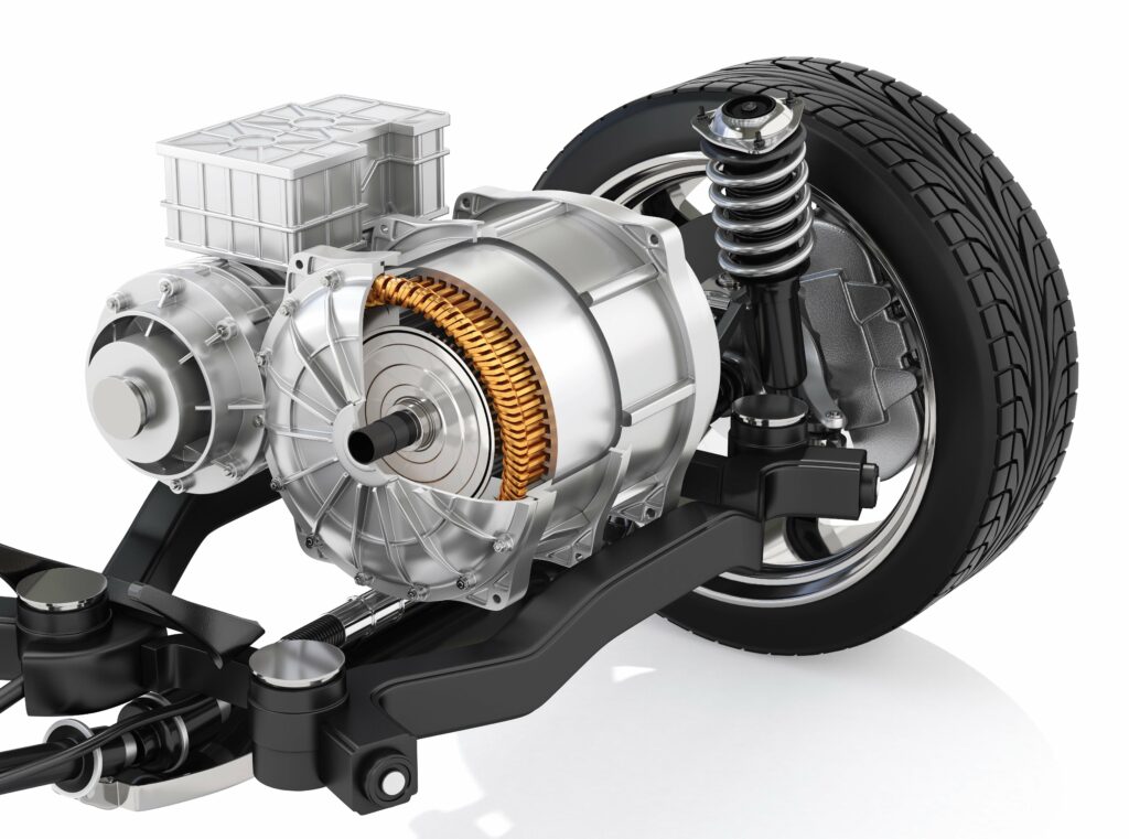
(Image courtesy of Allegro Microsystems)
The pursuit of power
Modern inverters are including more intelligent features to work with other vehicle systems, reports Peter Donaldson
Inverters do the conceptually straightforward job of converting an electric current from DC into AC form. As such, they create an essential link between the energy storage system and the motor.
Modern inverters use solid-state semiconductor switches, connected to form combinations of half-bridges and activated by smaller switching circuits known as gate drivers, which in turn are under the control of processors that implement control logic embodied in hardware, software or both.
Inevitably, there is a push for greater efficiency to reduce energy losses during power conversion and thereby eke more mileage from a battery charge, says an expert from a developer of advanced semiconductors and control algorithms.
At the same time, vehicle OEMs and powertrain specialists are pushing for lighter, more compact inverters without sacrificing performance. High torque- and power-density in both volume and weight terms are crucial to save space in a vehicle and reduce its overall weight, particularly as inverters are integrated into electric drive units (EDUs).
To meet these demands, inverter developers are increasingly turning to wide bandgap (WBG) semiconductors, such as silicon carbide (SiC) and gallium nitride (GaN). Compared with silicon insulated-gate bipolar transistors (IGBTs), transistors made from these two materials can operate at higher temperatures, voltages and switching frequencies, all of which contribute to higher power-density and efficiency. However, this also generates more heat in smaller spaces, driving the need for advanced thermal management.
Inverters are expected to work in vehicles for decades over hundreds of thousands of miles in a wide range of conditions, so reliability and durability are important.
In early electric vehicles, the inverter was engineered as a stand-alone unit, but the recent shift to integration with other components brings challenges in optimising packaging, says a specialist in electric machines, power electronics and control systems.
Understanding the location of the inverter on the vehicle, along with the associated environmental constraints that must be considered, has an impact on engineering and development requirements. This integration with other vehicle systems means that modern inverters must also incorporate more intelligent features to work with these systems, including adaptive control algorithms that optimise performance based on driving conditions.
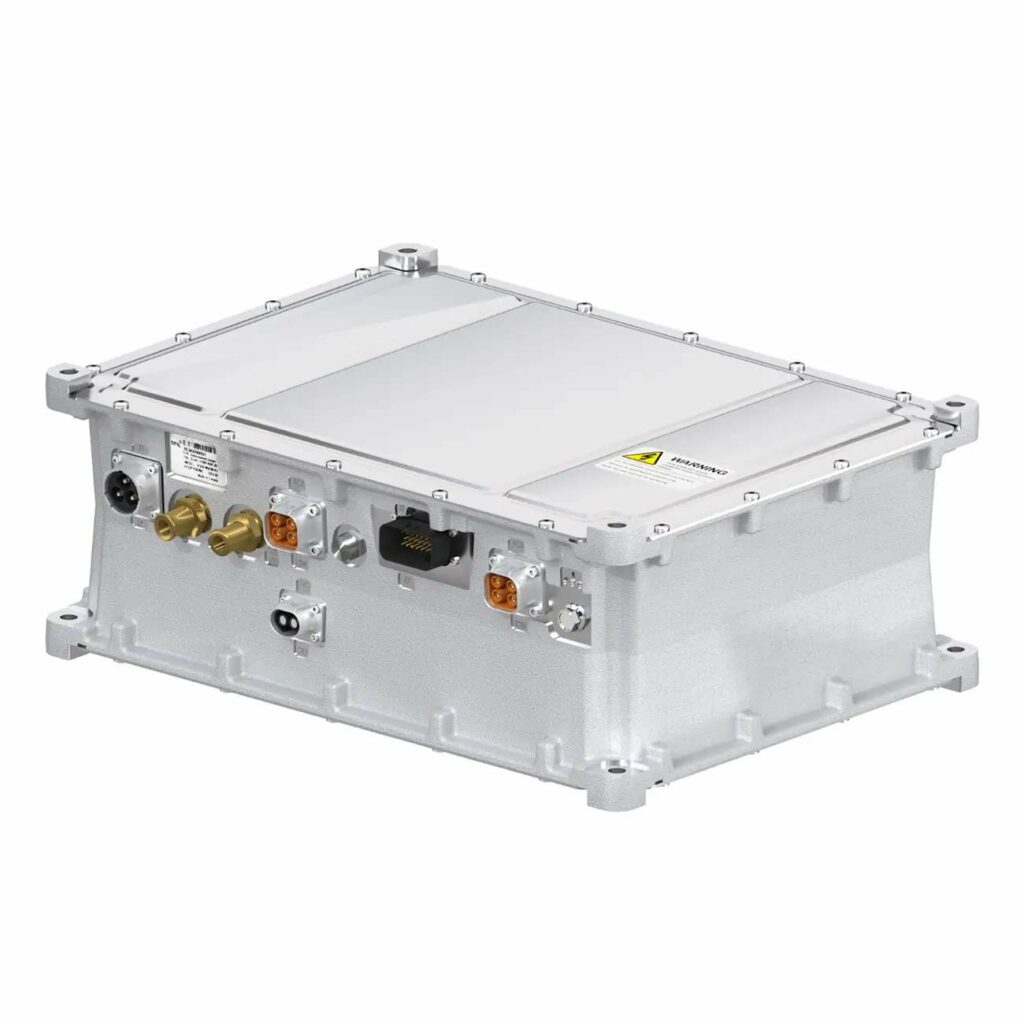
(Image courtesy of Allegro Microsystems)
Price and charge time
In the car and light commercial vehicle markets, EV manufacturers are working to lower the two main barriers to EV acceptance of price and charge time, according to our global automotive technology company.
Battery EVs are still a lot more expensive than equivalent vehicles with internal combustion engines (ICEs), and most of this extra cost comes from the very large battery packs that must be fitted to address range anxiety. Such big packs take a long time to charge, so we can add charge anxiety. Charge speed, therefore, has become a differentiator for leading EV manufacturers, the company’s expert says.
E-mobility, of course, covers a wide variety of applications, from on-road and off-road vehicles and industrial mobility to marine and aerospace vehicles, all of which have their own requirements, a leading traction inverter and BMS developer points out. Some high-volume, cost-sensitive applications such as two-wheelers are focused on reducing price while increasing safety, whereas aeronautics and related applications concentrate on power density, weight and safety, the company’s expert says.
Proof-of-concept integrations are increasingly important to demonstrate the benefits of new systems to vehicle developers. “To squeeze all the potential of an inverter-motor combination into each vehicle is a complex task that requires a lot of engineering knowledge and experience plus weeks of testing. We have seen efficiency gains of 4-7% or torque gains of up to 35% just by swapping to our inverters from other very well-known inverters available in the market,” he says.
A 35% gain in torque would require at least 35% more current to be pushed through the motor by the inverter.
One of the most significant new demands on inverter technology in recent years has been the move to higher voltages, says an expert from a high-current power-switching, motor control and software company.
“We’ve seen the move from 400 V up to 600 V, and now 800 V is about the standard. Whether it will move far beyond that is still uncertain. Of course, the higher the voltage, the higher we can drive the efficiency in the inverter, which will either improve range or reduce battery size. One of the hard limits with voltage is that you need to be certain you can isolate all the systems. Even at 800 V to 850 V bus voltage, you already need to use devices with 1,200 V maximum capability just to withstand the ripples and peaks. If you move beyond that, you start to get into trouble with isolating distances between all the high-voltage parts,” the expert adds.
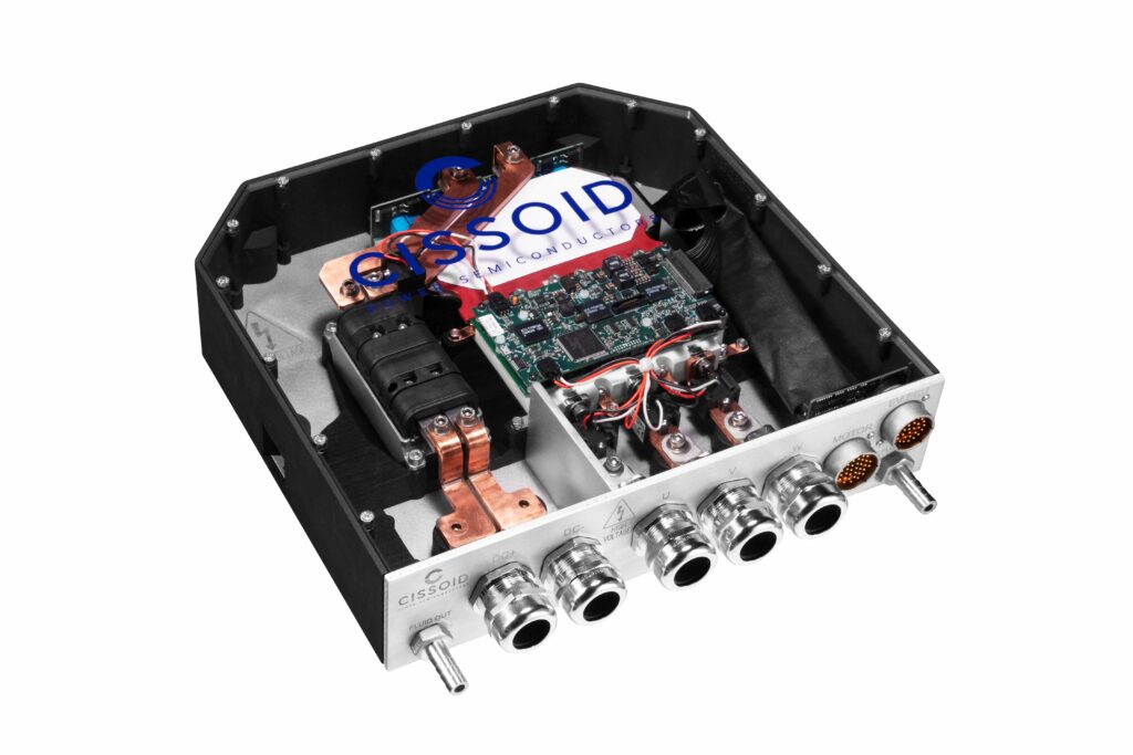
(Image courtesy of Cissoid)
Key parameters
When specifying an inverter to drive a motor, matching its power output with the application’s requirements is fundamental, while high efficiency is essential for making the most of the available power and minimising losses, notes our developer of advanced semiconductors and control algorithms.
Switching frequency affects both efficiency and the quality of the output waveform, with higher frequencies enabling the use of smaller passive components (such as electromagnetic interference filtering (EMI) inductors), but potentially increases losses, the expert says. The inverter’s ability to dissipate heat is crucial as it affects reliability, durability and longevity.
“The output of an inverter is a controlled AC current with a DC voltage limitation, meaning the DC link limits its capabilities,” says a leading developer of light, medium and heavy-duty traction inverters. “You need to be able to specify the electric machine performance at the minimum DC link voltage, and that determines the current requirements of the drive.”
He says the output of the inverter that makes the motor produce torque is current, and both the peak current capacity and how long it needs to be delivered are important to specify, as they affect cooling requirements. Knowing the maximum fundamental frequency of the motor is also crucial. This depends on parameters such as maximum rpm, and the number of magnetic poles. Knowing the maximum fundamental frequency determines the control frequency needed to calculate the required duty cycles and therefore create the current waveform at that speed, he explains.
Our traction inverter and battery management system (BMS) developer argues that the crucial item in an inverter or any power device that goes into a vehicle is the microcontroller because of the increasing importance of safety requirements and cyber security norms. “If the micro is not ready to implement those functions, the vehicle might be compromised at some point,” he says.
The firm uses the latest-generation Aurix microcontroller, which is certified to ASIL D level under ISO 26262 regulations.
“Vehicle integration engineers should understand the safety goals at vehicle level, and define the technical safety concept to achieve them. Engineers also need to understand the safety mechanisms the inverter has available, and learn from the supplier what safety strategy they use in the product. For some applications, it is not common to find ISO 26262-compliant products, and even less so to find suppliers who are open to sharing documentation with the customer to provide evidence of safety.”
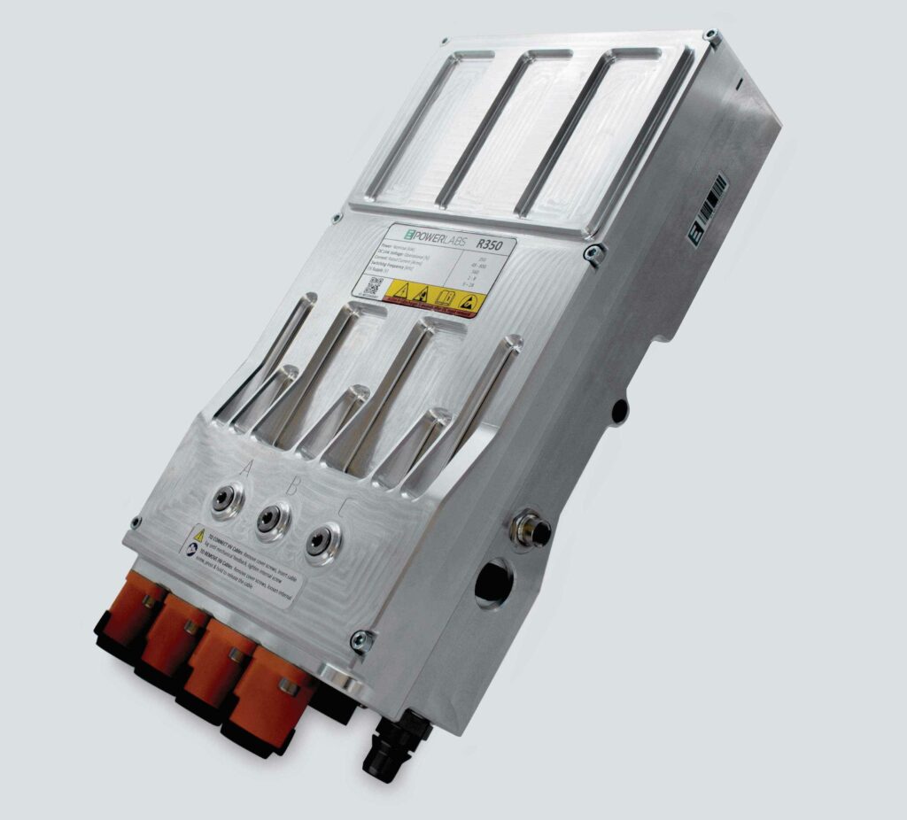
(Image courtesy of EPowerlabs)
Considering efficiency
Efficiency is also important, he adds. While virtually every inverter is said to have peak efficiencies in the high 90s in percentage terms, that peak is less relevant than the efficiency map as a whole. Even with large vehicles, the benefits of the compactness from high power density are important for vehicle integration and power management, he says. In some cases, numerous inverters for traction applications and auxiliaries may be required, garbage trucks being a good example, and finding space for as many as four or five inverters can be challenging.
At the other end of the scale, he points to the debate over whether light vehicles, such as two-wheelers, should run at low voltage, defined as under 60 V, or jump to high voltage. “The higher the voltage, the lower the currents for the same power, and that will make the electrical system cheaper, more efficient and enable features such as faster charging.”
The trade-off here is the cost of the isolation and connectors, etc that are required above 60 V, where the electrical safety requirements change significantly.
The efficiency of the EDU is always the first consideration before the inverter, according to the global automotive technology company, whose expert says: “The best-case efficiency for the inverter will be very low switching frequencies and minimised current levels through the power stage. However, these choices can be detrimental to overall system efficiency. The largest contributor to losses in the EDU is the traction motor. Therefore, a key objective for the inverter is enabling loss reduction through motor downsizing, as well as advanced control methods to generate more useful magnetic flux.”
Beyond motor considerations, inverter efficiency is increased by high-voltage architectures because lower currents reduce losses. Also, component and module integration within the inverter makes the overall package smaller and lighter, and the lowest possible resistance between the dies in the power stage and the cooling channel eases thermal management. However, there may be higher switching losses and EMI, and possibly higher resistance from high-voltage transistors, which also need more space around them for isolation.
Another aspect to consider is material availability, the auto company expert argues. “With supply chains already squeezed, the fewer materials needed for manufacture, the better. By reducing the copper usage in an inverter, the engineer can make significant savings in terms of cost, weight and sustainability, while still improving power and efficiency.”
There is still considerable scope for improvement, particularly in reducing switching and conduction losses, according to our advanced semiconductors and control algorithms company. “Advancements in semiconductor materials, switching techniques and control algorithms are areas where significant gains can be made,” its expert says.
Efficiency maps are important in judging such improvements because electric motors usually move around the entire map during operation, and it is vital to know the efficiency at all operating points before choosing an inverter or a core switching technology, our traction inverter and BMS developer expert says. Its expert notes that state-of-the-art inverter technology can vary in efficiency from 80% in low-speed applications to 98% in high-speed, high-torque ones.
A more efficient semiconductor is no more important than a good thermal design or a good control algorithm, the expert adds, noting they are twice as expensive as IGBTs in some cases and can bring electromagnetic compatibility issues. In response, the company has developed an advanced switching functionality that combines various techniques to increase inverter efficiency all over the operating map, and guarantee motor stability and performance, even when using IGBTs.
While the few percentage points of efficiency yet to come in electrical efficiency may not seem like much, they can have a significant impact on cooling. For example, an inverter handling 200 kW at 99% efficiency still generates 2 kW of heat that must be removed from the system, according to the expert at our power-switching, motor control and software company, who reckons there is still considerable room for improvement in thermal management.
“The efficiency of the cooling solution affects how much weight you need to add to the overall system. Hence, we’re seeing more use of liquid cooling and improvements to it, such as single oil cooling, direct cooling and nozzle-cooling systems,” the expert says.
From another perspective, chasing further efficiency gains in the inverter when the percentage is already so high is of only marginal benefit, and there is more to be gained elsewhere. “I’m good with 99%, so I’m going to focus on other areas of the drive system where we can actually have an influence, particularly the electric machine,” says the expert from our developer of light, medium and heavy-duty traction inverters.
Power density
The variables determining power density in an inverter are volume/weight and current capability. For the same voltage and volume, the higher the current capability, the higher the power density, while the peak current capability defines the maximum output of the inverter.
The difference between the peak and the continuous current is directly related to the heat management design of the inverter, says the expert at the traction inverter and BMS developer. “The better the thermal design, the smaller the ratio between peak and nominal, and thus the inverter will be more power-dense for continuous activity.”
Specifically, the combination of thermal mass and thermal resistance drives the peak to continuous ratio, so a large heat sink with a large thermal mass compared to its thermal resistance will increase the ratio.
The company’s development approach is to consider the inverter as a system formed of subsystems, and to focus on both efficiency and heat management. “This has allowed us to maximise all subsystem integration efficiency, and reduce volume and weight, while improving cost reduction and manufacturability,” he says.
In low-voltage inverters (below 60 V) for light-mobility applications such as two-wheelers, he says the company has achieved 5x to 8x the current and therefore power density of typical solutions on the market. For high-voltage products, its benchmark is 30 kW/kg, while its large automotive inverters achieve between 15-30 kW/kg.
Our light, medium and heavy-duty traction inverter specialist has developed a 48 V system capable of delivering up to 60 kW. Its expert says the limiting factor is the DC link current. Pulling 60 kW from a 48 V battery invariably draws over 1.5 kA. The DC connections to handle this current need large, heavy and expensive conductors.
Thermal management problems are a frequent limiting factor when it comes to power density. As this parameter increases it becomes more difficult to remove the generated heat. Here, less lossy advanced semiconductors are complemented by the advanced cooling technologies mentioned above, along with others such as phase-change materials and the optimisation of cooling system designs, says the expert from our advanced semiconductor and control algorithm developer.
Along with their advantages, advanced semiconductors also come with drawbacks, one being increased EMI, according to the power-switching, motor control and software company. “If you drive up the switching frequency to reduce component size, you also introduce a lot more switching noise,” he says. “At a certain point it starts to balance out how much space you can save, because you then need to introduce larger filter elements, so there’s a certain sweet spot that technologically we can’t get through at this point.”
The packaging of the power semiconductor devices also has a strong impact on power density, says our expert in electric machines, power electronics and control systems. “A modular design, optimised for reuse using individual half-bridges won’t be as dense as another one optimised for a specific application using a six-pack configuration. Architectural decisions should be made considering this trade-off,” he explains.
The DC link capacitor can amount to up to 30% of an inverter’s volume, he adds. “Its volume can be minimised by accepting a higher-voltage ripple or using switching strategies to reduce it. Size reduction can also be achieved by using thinner insulation materials or new types of material.”
While power density is strongly affected by cooling performance, extra cooling can indirectly reduce the efficiency of an inverter based on SiC metal-oxide semiconductor field-effect transistors (MOSFETs) if the designer chooses to push more current through them. This is because they present resistance and their losses rise with the square of the current, the traction inverter developer expert points out.
In the company’s latest inverter family, the solution was to run more MOSFETs in parallel to meet the current requirement while minimising the resistance between the drain and source terminals with the switch ‘on’, and using a low-cost, low-performance thermal junction to a simple heat sink.
A question of topology
Inverter designers can draw on different topologies to meet the needs of their applications. The topology is the specific arrangement of the components and circuitry, which defines how the switches, capacitors and inductors are connected, for example, and how they interact to achieve the desired DC to AC (and vice versa) conversion.
Most of the inverters used in e-mobility applications are of the voltage-source inverter (VSI) type, which are designed to provide a constant voltage output and adjust the output current to meet load requirements.
Most of these are of the two-level type that switch between two voltage levels, which typically correspond to the positive and negative values of the system’s DC bus voltage. A third level of 0V is achieved in the ‘off’ portion of the duty cycle, which allows the motor current to freewheel through the power devices, rather than the DC link capacitor, reducing the ripple current on that component.
However, multi-level inverters (MLIs) are attracting interest for high-power applications. MLIs switch between multiple voltage levels to approximate a sinusoidal waveform more closely, and they can achieve higher voltages with lower harmonic distortion and reduced stress on components at the cost of increasing the complexity of the inverter hardware and controls.
There are different topologies of multilevel inverters, including neutral-point clamped (NPC) and three-level neutral-point clamped (T-NPC), for example. Their benefits vary according to the duty cycle, says the specialist in electric machines, power electronics and controls.
The basic NPC topology provides three voltage levels. It has a neutral point that is clamped to the midpoint of the DC bus voltage, creating three voltage levels. T-NPC extends the NPC topology to provide additional voltage levels; adding an extra switching leg to increase the total number of voltage levels to five. As might be expected, MLIs with T-NPC topology can create a smoother output waveform with reduced harmonic distortion at the cost of greater complexity, particularly when it comes to control software.
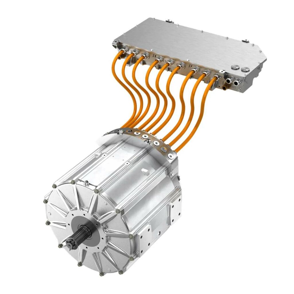
Despite their benefits, multi-level inverters essentially present the same performance limitations as a conventional two-level, three-phase system in providing a wide range of speed and torque, says our traction inverter developer’s expert. The company has tackled this in its latest inverters with a new use for the established technique of switching the motor-winding connection scheme between series and parallel in real time.
“You’re changing the effective number of turns on the motor’s stator coils. In series mode, you have twice as many turns in parallel, so at low speed you can effortlessly create large amounts of torque. Then, as the speed increases, the machine is switched to parallel, so the back EMF is cut in half. Torque is also cut in half, but now the power delivery at speed is achieved relatively easily and efficiently since field weakening is not required until much higher speeds are reached, if at all.
“We gain a lot of efficiency on the motor side because we don’t have to push the field-weakening D-axis current into the motor to enable it to produce torque at high rpm. If you take a machine from 90% efficiency to 95% at high speed, which is where most of the power is consumed, it has a much more significant impact on the efficiency of a vehicle.”
(Image courtesy of Exro Technologies)
Flavours of control
Remarkably, the simple process of switching power transistors on and off is amenable to several methods of controlling AC motors with inverters. Control is key to the stability and reliability of the drive system, and is applied to motor parameters such as torque, speed, voltage and safety-related functions. All control schemes for EV motors use pulse width modulation (PWM).
PWM controls the voltage applied to the motor by adjusting the width of the pulses in the waveform. Essentially, it varies the length of time that the switches are on; the longer they are on, the closer the output is to the maximum DC voltage. PWM’s main advantage is simplicity. Drawbacks include limited precision compared with more advanced methods and the potential for higher harmonic distortion in motor currents.
A refined PWM scheme, known as field oriented control (FOC), aligns the stator-current vector with the rotor’s magnetic-flux vector to achieve independent control of torque and flux. FOC yields high efficiency and a quick, dynamic response. However, it requires accurate information on rotor position, which usually comes from encoders or sensors. Also, FOC algorithms are complex, primarily because of the need for coordinate transformations to align the vectors.
Direct torque control (DTC) regulates torque and flux without needing coordinate transformations, yielding fast responses, so it is well suited to high-performance EVs. However, it can lead to torque and flux ripple, causing vibration, and it is sensitive to variations in motor parameters such as resistance and inductance in rotor and stator.
Advanced control methods such as DTC and FOC implement a control loop connecting the traction inverter to the vehicle. “The normal approach is to give the motor-inverter set a torque-control command, says the expert at our traction inverter and BMS developer.
“The vehicle sends a torque set-point request, and the inverter converts the desired torque command into phase-current output to command the motor. The feedback of the measured current is then used as feedback for the vehicle control unit (VCU) to calculate the real torque output. A good inverter calibration should be able to provide a torque accuracy better than +/-5 Nm at all operating points.”
To try to simplify inverter control, our traction inverter developer is working on technology that turns a voltage-source inverter into a current-source inverter. “There’s still PWM and a voltage fed into the machine, but the processing of duty cycles is handled differently,” its expert says. “Basically, this is an AC peak-current controller. It can follow the same switching pattern as a space-vector modulation (SVM) controller, minimising the ripple current on the DC link.”
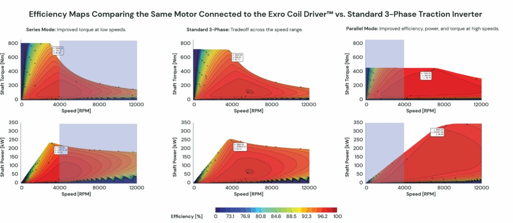
at high speed, compared with a conventional three-phase inverter
(Image courtesy of Exro Technologies)
Software boost
In modern EVs, all these control methods are implemented in the software that runs in the inverter’s microcontroller, under the ultimate command of the VCU. The software affects system performance through the switching strategy, says the electric machines, power electronics and control expert.
“Novel switching patterns can minimise losses for both the inverter and the motor, and can be introduced remotely via over-the-air updates. Derating models can also be improved over time to allow for more efficient usage of the traction system,” he says.
Naturally, there is significant scope for improvement through software, particularly in the realms of control algorithms and optimisation, says the advanced semiconductor and control algorithm developer. This enhances efficiency, improving thermal management and dynamic adaptation to varying load conditions.
“Depending on how much torque or speed is needed from the motor at a given moment, the software can switch how the motor is driven,” our power-switching, motor control and software expert notes. “What we are seeing is that you get improvement in efficiency, and it also reduces switching noise and eddy currents in the motor. That means you heat up the motor less.” This, he says, simplifies thermal management.
Gate drivers
Microcontrollers lack the electrical punch required to switch the IGBTs or MOSFETs directly, so they rely on gate drivers.
“High-performance gate drivers are crucial for controlling the latest inverters, especially those using wide-bandgap semiconductors, such as SiC and GaN, says our developer of advanced semiconductors and control algorithms. “They ensure precise control over switching operations, minimise switching losses, and protect against over- and under-voltage conditions. Fast, accurate gate drivers are essential for achieving the full performance and efficiency benefits of modern semiconductors.”
They can also simplify inverter design by achieving safety-related functions, and help protect the health of the motor, says the specialist in electric machines, power electronics and control.
Motors operating at 800 V and above are more prone to partial discharge, says a traction inverter and BMS developer, compromising the motor’s electrical isolation and, consequently, its durability. “The higher the voltage overshoot, the higher the risk of partial discharge. And the higher the switching frequency, the faster that occurs. Fast-switching SiC inverters are provoking this problem, which the industry is working to resolve,” the expert says. The company has developed and implemented gate-driver functions to control the voltage overshoot dynamically and prevent problems such as partial discharge.
The expert from our traction inverter developer notes that to control a SiC MOSFET, gate drivers need to meet two basic criteria. “It has to have the pulse-current capacity to be able to charge the gate capacitors in the amount of time that you want them to, and, conversely, to discharge them,” he says. “The gate driver has to have a fairly low output impedance so that it is not influenced by other devices to cause spurious turn-on, for example.”
Gate drivers are also relied upon to handle anomalies arising from high switching speeds, very efficient energy delivery to the motor, and increased sensitivity to over-current and over-voltage conditions. These can lead to motor runaways in permanent magnet machines that cannot be controlled by switching the current off, because the motor converts its own kinetic energy into current to drive itself.
While the inherent losses in this process will eventually stop the motor, this can take a dangerously long time. “So, we have a whole raft of protection measures in place within the gate drivers to prevent runaway events,” says the expert from our power-switching, motor control and software company.

Future trends
Looking ahead, our experts anticipate the expanded adoption of wideband semiconductors, higher voltages, further efficiency improvements, advanced cooling solutions and better control algorithms. Some expect pressure for more efficiency from inverters and e-machines to increase range before new battery technologies come to the fore, instead of fitting ever larger batteries.
More electromagnetic compatibility challenges are likely to result from these efficiency improvements, says the global automotive technology company expert, who also expects increased integration of the inverter into the EDU.
There will also be further integration of inverters with other power electronic systems, such as DC-DC converters and onboard chargers, according to our traction inverter and BMS developer.

Acknowledgements
The author would like to thank the following people for their help with this article: Carsten Himmele, technical sales engineer at Allegro Microsystems; Mike Sandyck, marketing director at Cissoid Power Semiconductors; Francois Dube, senior manager, traction inverter product engineering at Dana; Jon Duroudier, CTO at EPowerlabs; Eric Hustedt, CTO at Exro Technologies; and Ben DeLand, director of electrical hardware engineering at GKN Automotive.
Some suppliers of inverters
Belgium
Cissoid
+32 10 48 92 10
www.cissoid.com
Canada
Exro Technologies
Dana TM4
Denmark
+1 587 619 1517
+1 450 645 1444
www.exro.com
www.danatm4.com
Danfoss
+45 74 88 22 22
www.danfoss.com
Germany
Infineon Technologies
Hofer Powertrain
Italy
+49 89 234 0
+49 7022 217 884 0
www.infineon.com
www.hofer.de
Marelli
Zapi
Spain
+39 051 615 7011
+39 0522 960050
www.marelli.com
www.zapigroup.com
EPowerlabs
Switzerland
+34 943 466 286
www.epowerlabs.com
ABB
STMicroelectronics
The Netherlands
+41 43 317 7111
+41 22 929 2929
www.abb.com
www.st.com
NXP
UK
+31 40 272 9999
www.nxp.com
GKN Automotive
McLaren Applied
USA
+44 121 788 4000
+44 1483 261 400
www.gknautomotive.com
www.mclarenapplied.com
Allegro Microsystems
BorgWarner
Curtiss-Wright
Eaton
Texas Instruments
+1 603 626 2300
+1 248 754 9200
+1 704 869 4600
+1 248 226 6772
+1 972 995 2011
www.allegromicro.com/en
www.borgwarner.com
www.cw-industrial.com
www.eaton.com
www.ti.com
Click here to read the latest issue of E-Mobility Engineering.
ONLINE PARTNERS

