


Fuel cells
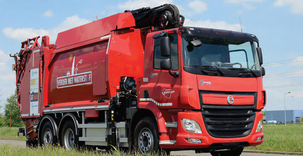
(Courtesy of E-Trucks Europe)
Nick Flaherty explains the issues at play when designing and building a fuel cell.
Conversion factors
Sometimes it seems that the specification and design of a fuel cell is more of an art than a matter of engineering. While the basics of the cells are clear, most often based around a stack of proton exchange membrane (PEM) cells that use hydrogen to produce electricity, the design and development process is rather more complex.
This involves specifying the stack, the ancillary units for handling the hydrogen, the controller hardware, firmware and algorithms, as well as the power management, rectification, DC-DC conversion and any battery or supercapacitor support.
The design of a fuel cell is also not just about its raw power. With cells being used in trucks, cars, inshore and offshore boats, cargo shipping and now even passenger aircraft, the specifications for each are very different. That leads to variations in their peak and sustained power: for example, electric boats demand high levels of sustained power.
Stacks can vary anywhere from 10 kW to 2 MW, but there is a balance between the peak power of the stack and the amount of power an electric platform might need.
That can be because cost is also a key consideration. Some fuel cell designs that are sized for peak power demand can be prohibitively expensive to construct – the stack varies from $500 to $5000/kW, depending on the design – but a hybrid system with a battery pack or supercapacitor can be used to reduce the peak power requirement and overall cost. However, this also has implications for the overall lifetime of the powertrain.
The sweet spot for most fuel cell designs is 80-100 kW, but that comes at a cost of $60,000 – more than the price of an electric car. The challenge is to bring the cost down for mainstream fuel cell designs as well as for commercial platforms such as refuse trucks or buses, which tend to need higher power of around 200 kW.
These figures relate to PEM fuel cells, but there is another fuel cell technology that uses a solid oxide fuel. This solid oxide fuel cell (SOFC) requires the fuel to be heated up to generate the hydrogen, which makes it safer and easier to refuel than using liquid hydrogen. However, the heating takes time to produce power, so the technology tends to be used in range extenders to charge up a battery EV.
The scaling analysis of how much power a fuel cell can produce is not just about the size of the stack. For example, if a 50 kW cell is required, how big does the compressor or coolant pump need to be, and how big is the battery pack? The fuel cell might provide a longer range than a battery pack but the size of the stack is not about the capacity; it is the discharge and charge limits, as well as the instantaneous loads.
One way to address the challenge of the design and scaling of a fuel cell is to use simulation. This relies on a model that can size different packs, for example to ensure the sustained power under varying conditions, called the transient limitation. The transmission system might include a battery or supercapacitor, so the simulation needs to have a battery modelling capacity with detailed chemistry of the batteries as well as a supercapacitor model.
Stack-level model
One way to simulate the physics of a PEM or SOFC stack is to break it down to the individual cell. This consists of a membrane electrode assembly (MEA) and two flow-field plates delivering about 0.5-1 V. The typical optimum cell voltage is 0.6 V, with a current density of 2.5 A/cm2, and these are then stacked to achieve a higher voltage and power.
The power output of a given fuel cell stack will depend on its size. Increasing the number of cells in a stack increases the voltage, while increasing the surface area of the cells increases the current. The stack is finished with end-plates and connections.
For the simulation, an individual cell can be modelled and the behaviour extrapolated to multiple cells. The model can also be used to provide the boundary conditions for the rest of the system – the supply of air and hydrogen, the humidity and other factors.
In this way the stack model is used as the heart of the fuel cell’s development. This leads to the size of the stack, the controls and the electrochemistry.
Using the stack as an object in a map-based object-oriented simulation tool allows the model to connect to the different domains, connecting flow objects for air and hydrogen, coolant channels within the stack or directly to an electrical circuit such as a battery and motor in a vehicle model.

A polarisation curve can be used to provide the reference conditions for the model, then as the supply of reactants and pressures changes, sub-models can be used to adjust the performance of the fuel cell accordingly. This process includes modelling the catalyst deposits, the diffusion layers, the porosity and the thermal properties.
That then leads into the design of the bipolar plates in the stack. There are a lot of different ways to arrange channels in the cell, from parallel flow to serpentine and interdigitated. An alternative is to use a metal foam flow pad that has a porous ‘flow field’ rather than channels.
Linking the stack model to a control model allows for virtual calibration. This should be as physically realistic as possible for control calibration without having to go to a dyno for testing. Such models provide a deviation of less than 5%, reproducing all the trends and system-level performance.
The key is to model the electrochemistry accurately. Once that is achieved, the simulation shows how much heat and voltage is being generated. That gives confidence of what’s going on in the cell, both initially and over the lifetime of the system.
For example, it is possible to analyse the stack’s performance over its lifetime to show the change in temperature and state of health. This can show the gas concentration gradients throughout the cell and how that changes over time, how the humidity or temperature changes, and the concentration of reactants at the inlet versus the outlet.
There’s also a lot of interest in extending the simulation of the stack for thermal modelling of the rest of the system. This uses the stack as the boundary condition for thermal management models of other parts of the system, such as pumps and the heat exchanger. For example, directly integrating the coolant into the system increases the temperature of the coolant, as it draws more heat out of the system and changes its overall performance.


Bipolar plates
Bipolar plates can be made from thin metal or graphite, as they act as the conducting anode and cathode in each cell.
The big difference between PEM and SOFC stacks is that most PEM cell designs incorporate a coolant channel, which sits between the anode and cathode plates. Some stacks are cooled using air or water injection, but most of them have the cooling channel as an intrinsic function, and it needs to be leak-tight.
Another function of the bipolar plate is to distribute the gases over a large surface and optimise the flow to make sure the reactor will work optimally without needing a lot of energy for pumping. The channels used to optimise the flow can be straight, dimples or bumps, serpentine or zig zags; there are many different types.
(Courtesy of Symbio)
What is key though is that there is no best kind of bipolar plate – it depends on the design, stack dimensions and coatings, all of which vary according to the application. For example, a fuel cell in a satellite that is running for 100,000 hours has a very different design from one in a minibus that has to run for only 5000 hours.
In a typical PEM fuel cell there are differences between graphite and metal plates. The metal plates are typically 0.1 mm thick and are flexible, but can be quite fragile. Stainless steel is used as standard, while titanium is better at resisting corrosion although its formability is lower. Milled graphite is brittle and doesn’t bend.
Metal plate production
The key issue here is the balance between surface area and manufacturability. There is a balance between quality and functionality of a stack and its cost.
This goes wider than the welding of the plates in the stack, it’s also the coating. If gold were applied on all the plates, for example, the stack would cost more than five or six internal combustion engines.
The biggest challenge is to use a coating to provide a metal component that is cost-competitive with carbon plates. Then there is the assembly of the plates with the welding, gluing and seals to make that cost-competitive.
A typical stack can consist of 300 to 400 plates, so constructing the stack needs volume tooling. Metal plates have more options for forming, from using water pressure to form the sheet to mechanical punching.

The key advantage of metal plates over graphite is lower weight and size, but the cells are a very corrosive environment, where good conductivity with low ohmic losses are vital for maintaining the performance of the stack. For example, running a stack in certain conditions can result in short-term changes to the gas flow, potentially leading to more corrosion.
That means there is a balance between whether the stack needs to be strong enough to address the potential risk of corrosion and the weight and cost of the plate. This highlights why managing the running conditions, including the purity of fuel and the sensors in the fuel cell, is also key.
For example, if a port is blocked and gas doesn’t flow, the cell goes into a different running mode. It becomes more like an electrolyte, the anode and cathode swap over and the chemistry changes in the stack. The coating can then become loose and corrosion occurs. The coating can clog the membrane, and over time the loss of the catalyst can reduce the performance of the stack by tens of percent.
That then leads into the type and cost of the coating. For example, coating with gold or some other noble metal at a minimum layer of 2 nm already exceeds the US Department of Energy’s target cost for a fuel cell.
In an SOFC it is the oxygen that moves through the membrane rather than the hydrogen, and the by-product is heat. Methanol rather than hydrogen tends to be used as the fuel, as it is easier to transport. This allows the plates to be thicker and stiffer, by 200-600 microns, but the SOFC operates at a much higher temperature of 400 C, so standard stainless steel cannot be used.
Instead high-temperature steel that includes chromium is used. The chromium can be released at high temperatures though, so the steel needs a coating of manganese and cobalt called spinel. This protects the steel by forming and re-forming, and the stack doesn’t need an extra channel for cooling.
Carbon plates
Carbon plates have their own advantages. They can be moulded for high power density automotive applications with a thickness of 1-1.2 mm. Graphite can be used where the power density is not so important, such as bus systems, as the plates are thicker. These operate at up to 85 or 90 C and cost less than carbon or metal.
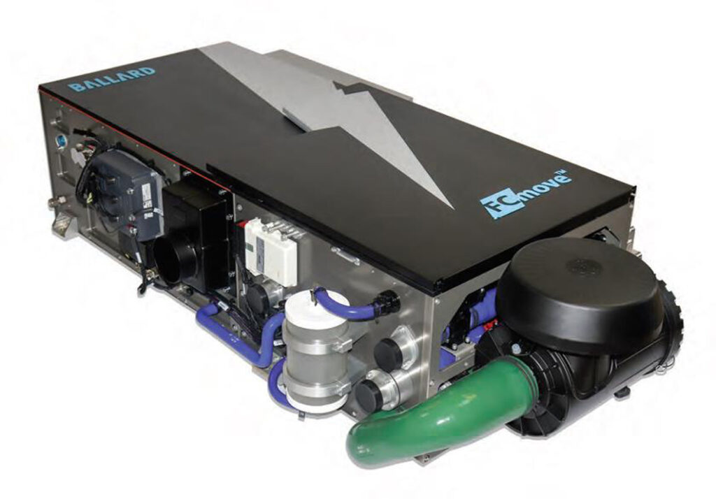
(Courtesy of Ballard Power Systems)
In a PEM fuel cell, the MEA is formed by placing a catalyst-coated membrane between two gas diffusion layers; the catalyst is platinum. When hydrogen gas flows across one side of the MEA and oxygen across the other, an electrochemical (non-combustion) reaction occurs, splitting hydrogen into protons and electrons, with the electrons being captured as electricity.
The amount of platinum catalyst-coated material used in fuel cells, known as platinum loading, has been successfully reduced over time. However, a carbon plate allows the use of a non-precious metal catalyst based on a carbon alloy material in the plate, which helps to reduce the cost of an air-cooled fuel cell stack even further.
Stack construction

There is a welding issue with attaching the frame to the plate. Positioning is critical during welding – it is easy to create a hole, but a stack can have 300-400 plates. That means there can be 1.5-2 m of welds over the plates, and that creates long welds where a small defect means it’s out of spec. The size of the welds, made using a laser, are key. The laser head on a welding tool has a capacity of 300,000 plates a year.
Then there is the sealing. Some designs put the gasket on the membrane, some on the bipolar plate, while others have gas-giving components stacked separately.
These seals can be created by injection moulding onto the membrane or plate or by screen printing. Dispensing a sealant onto the plates is another potential method, as it can compensate for imperfections by varying the thickness of the seal. However, there are scalability issues for high-volume production.
Measuring the cell voltage
The fact that not all fuel cell stacks are the same becomes apparent when designing a system to monitor the voltages of each cell. For various reasons, the potential tap at the bipolar plates of a fuel cell stack presents a particular challenge.
There is only limited space available in a vehicle’s ‘engine’ compartment. A cell-contacting element with a conventional overall height of between 35 and 250 mm takes up too much valuable space. It is also important to minimise the work involved when installing the cell-contacting element at the fuel cell stack – not least with a view to series production.
At present, spring contacts are often used for voltage tapping at fuel cells. These are not only very tall, they also have to be adjusted by hand. Such adjustment is very awkward given that the cell spacing is less than a millimetre in modern fuel cells.
One way to overcome this is to use a cell-contacting unit that measures the cell voltage pick-up (CVP) via spring contacts. This ensures reliable voltage tapping without the need for tedious re-adjustment by hand on installation. The entire contacting unit is attached to the end plates and – if applicable – to a central plate of the fuel cell stack.
The contacts are for the most part automatically centred in the cell pockets, thus ensuring short installation times. And a height of just 5 mm is an added advantage of the contacting unit.
Bipolar plates and pin contacts
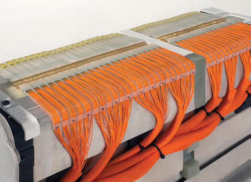
Monitoring the voltage of the bipolar plates in a fuel cell stack
(Courtesy of SmartTest)
While some types of stack are provided with cell pockets that make them suitable for the solution described above, other types have holes or bores in the bipolar plate and so require the use of pin-contact solutions.
For an existing fuel cell stack with a cell-contacting unit, or a stack that is still at the development stage, the challenge is to find the appropriate CVP technology. This can lead to changes in the design of the bipolar plates to combine the plate and the CVP.
Alongside the limited space available in the ‘engine’ compartment and a minimum amount of installation work, there are other engineering challenges. For example, the contacting units have to be able to withstand the shocks and vibrations occurring during operation.
The mass production of fuel cell vehicles with integrated cell-voltage monitoring creates other challenges, one of which is cost. One-off CVP units are still extremely expensive to make, so the unit price will have to come down for use in mass-produced vehicles, even if the numbers are fairly small.
The varying number of cells in stacks means many different CVP modules are needed. The aim is to standardise the number of cells in future to reduce the number of modules required for the CVP.
However, the greatest challenge is to create CVP systems that need a minimum amount of installation work at the stack in combination with the highest possible degree of automation of the installation process. That means having to make allowances for the production and automation requirements when developing the CVP.
Integrating CVM and the CVP
The differing requirements associated with cell voltage monitoring (CVM) and cell contacting in fuel cell stacks means these are still separate systems at present. However, the aim is to successively merge the two elements into a single component. The crucial aspect of this is how to design the connection system to satisfy the requirements of the IP67 ingress protection standard.
The first step is to use a wiring connection with single-side disconnection on the CVM system end. The next stage would be to introduce connections on a flexible PCB. The CVM chips will then be located on the contacting unit as well.
Fuel cell design
The sizing of the fuel cell takes into account the maximum power point, which essentially is when a vehicle is accelerating at full speed. However, a bus or truck for example doesn’t operate at that peak; it is most often idling at a traffic light or moving through traffic, which requires a much lower power level. That means the current density in the stack tends to be lower and the voltage tends to be higher, at 0.7-0.75 V. This is very much governed by the chemistry.
This higher voltage and lower current density impacts on the control loop. The output from the fuel cell is a DC current and voltage, and one trick for sizing it is to match the power requirement and output voltage of the stack to the input of the motor.
Typically that will require DC-DC conversion, for example matching a 300 V output to a 600 V motor. The amount that the 0.7 or 0.8 V cell can be varied by the controller will be clipped by the DC-DC controller, and this leads to a combination of cells connected in serial and parallel.
One challenge for trucks is demonstrating that the fuel cell and hydrogen supply and pumps can fit into a vehicle in a cost-effective way, with enough storage capacity for the required range.
For example, a refuse truck can be retrofitted with a hydrogen tank challenges of sizing and specifying fuel cell stacks. and a fuel cell. The size and volume of the tanks varies from 15 to 30 kg of hydrogen, depending on the desired operating radius. Then a battery pack and a fuel cell are added. Thirty kilos of hydrogen is comparable to 300 litres of diesel, and a truck needs 8-10 kg a day. So with a tank volume of 30 kg, a truck can collect refuse for three days before having to refuel.
The location of the fuel cell, hydrogen tanks and the batteries may differ. On a side loader, the tanks are placed vertically under the cabin, which allows up to 20 kg of hydrogen to be carried. On rear loaders, the tanks are placed horizontally on the roof of the vehicle, with a volume of 15 or 30 kg.
Conclusion
An increasingly important design requirement is to get the right combination of cells in a stack to meet as many applications as possible. That then increases the volume production of standard components and helps to drive down the overall cost of the fuel cell.
Despite the complexities though, fuel cell systems are gaining ground in electric powertrains. This is requiring a change in the perception of cost though. Rather than focusing on the initial cost of the stack and the fuel cell, the total cost of ownership becomes more important.
For example, buses in London using carbon bipolar plates have run for over 30,000 hours before being replaced in a scheduled refurbishment in the same way as an internal combustion engine. This is several times longer than a battery pack could operate for, giving a cost saving over the lifetime of the vehicle.
That 30,000 hours is the accepted lifetime of a bus or truck, so improving the lifetime might not be an advantage. While a stack that runs for 50,000 hours is possible at a higher cost, the bus or truck operator might not value it, as there are other wear-and-tear items.
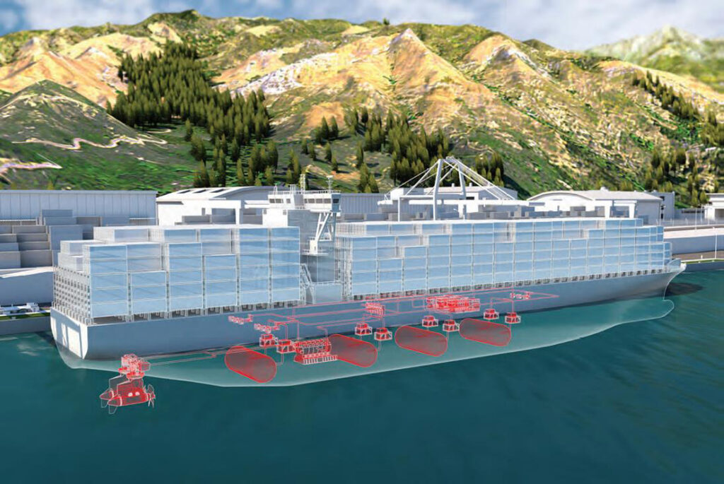
By contrast, a large container ship carrying 18,000 containers needs 60 MW of power, which is currently supplied by more than 80,000 litres of diesel a day. A fuel cell system for such shipping is currently in development. While a 60 MW fuel cell might not be necessary – as it would almost certainly be used to recharge a large bank of batteries to keep the ship moving – it highlights the challenges of sizing and specifying fuel cell stacks.
Acknowledgements
The author would like to thank Hendrik Geysen at Borit, Jake How at GTIsoft, Andre Beukers at E-Trucks Europe, Adam Huckstep at Hypermotive and Kevin Colbow at Ballard Power Systems for their help with researching this article.
(Courtesy of ABB)
ONLINE PARTNERS

