


HV measurement
(Image courtesy of Pickering Interfaces)
Driving test
Nick Flaherty looks at the latest developments in high-voltage test systems
Higher voltages mean more power but also more test challenges, and Nick Flaherty has been looking into the latest trends in powertrain testing.
High-voltage (HV) testing is an important part of the development process for an e-mobility powertrain. As the power and efficiency requirements increase, so too does the voltage required to keep the currents at a reasonable level. As battery packs move from 400 to 800 V and now to 1000 V and even 1200 V, the HV requirements rise accordingly, with 4 kV now specified as the standoff, or breakdown, voltage for many test systems.
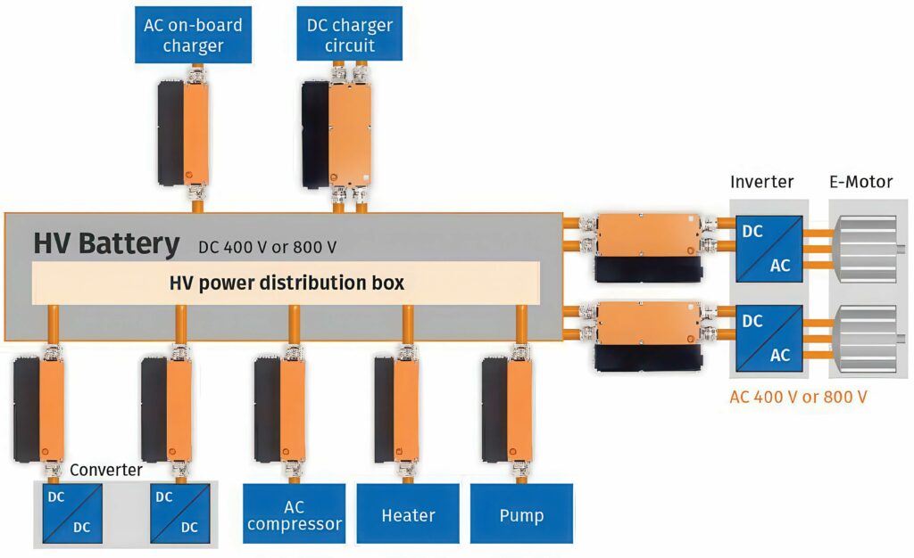
The HV vehicle electrical system in modern EVs connects various consumer systems with the HV battery. Connected inverters and converters cause retroactive current and voltage ripples in the HV DC circuits, which can cause damage to components. For this reason, vehicle manufacturers test and verify the HV vehicle electrical system quality to ensure safe operation of all consumer systems with all functions over the entire life cycle of the vehicle. In-house standards and the ISO 21498 standard (consisting of parts 1 and 2) serve as guidelines in this process.
However, this is not just about an HV differential probe for an oscilloscope, although that helps. E-mobility test systems need battery emulators and simulation hardware, and there is also an increasing trend toward more distributed tests to optimise every aspect of the powertrain. This is driving the need to combine temperature monitoring, vibration analysis and many other types of testing, alongside the HV measurements, with more sophisticated triggering schemes to capture rare events. This is requiring more complex test systems with bus or switching mechanisms.
Also, the same test schemes are being used for end-of-line testing, using the data gathered during development for testing to ensure that the system is safe to ship.
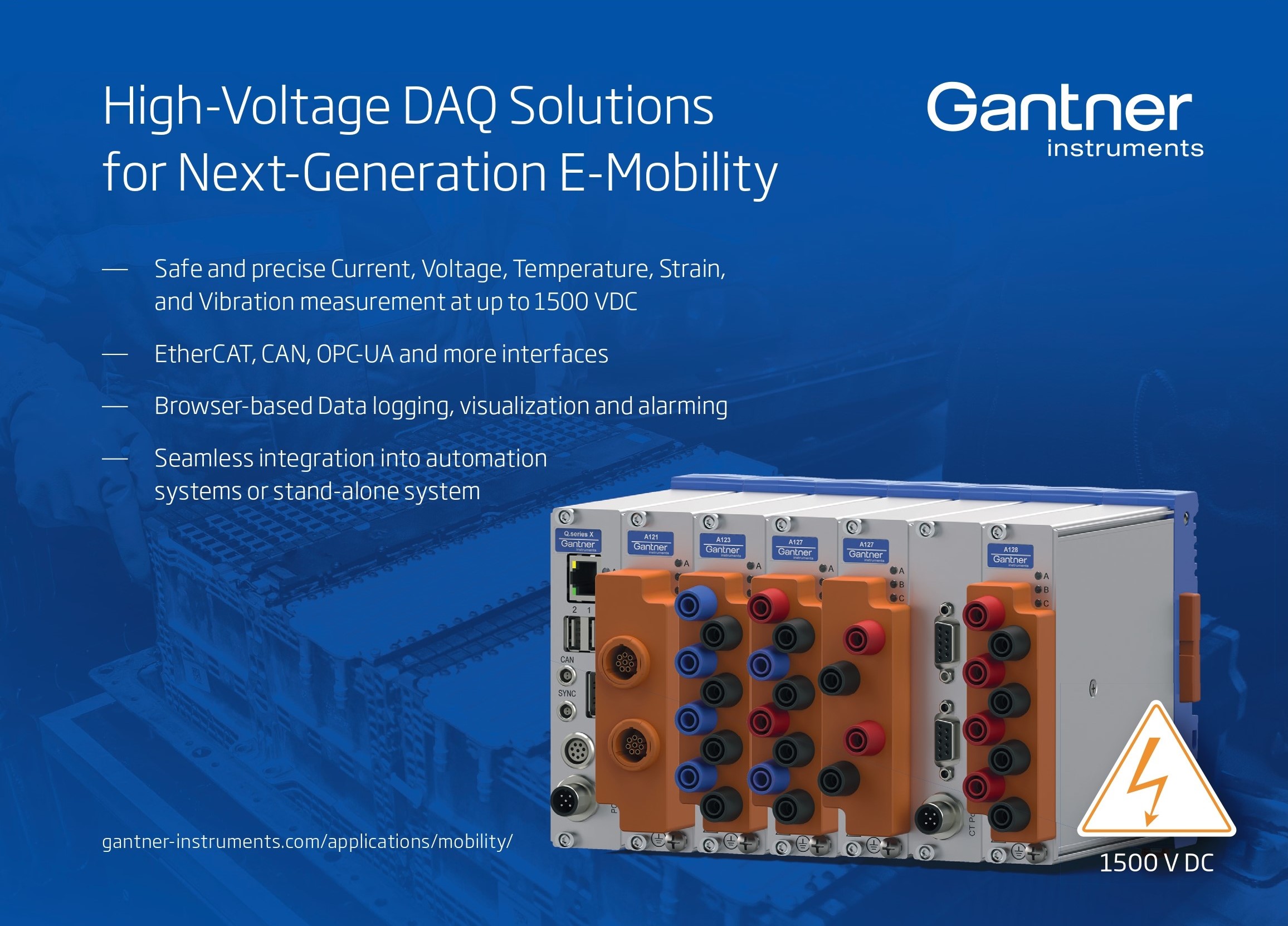
HV data acquisition (DAQ) systems offer up to 1500 VDC permanent isolation to ensure safe and accurate measurement of battery packs, modules and cells. A modular system allows for selecting specific connector types and can be combined with synchronised video streams for real-time monitoring with sampling rates of up to 4 MHz.
The growing complexities of modern EV and battery systems, and the use of higher switching frequencies and voltages, are driving higher measurement frequencies as well as a lower noise floor to improve the quality of results. A noise floor of below -140 dB and measurements at 4 MHz can provide accurate results, even in challenging testing environments.
(Image courtesy of Gantner Instruments)
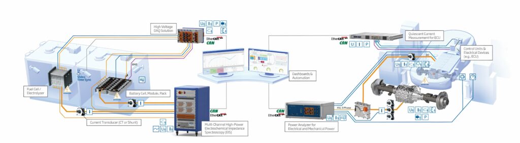
Distributed test
Testing the powertrain needs not just an electrical test of the voltage and current, but measurement of physical parameters such as strain, vibration, temperature, humidity and pressure from other sensors to find correlations, as well as data over the Controller Area Network (CAN) bus and the higher performance CAN FD variant.
This is not just needed for evaluation of prototypes in the lab to analyse system behaviour but also for production testing. For the powertrain, the test system can take the signals from the battery to the inverter and to the motor, and capture data from the ECU for commands regarding vibration on the motor and bearings. It can also monitor the temperature of the cooling fluid and the pressure in correlation with the performance of the motor.
One such system has eight input slots for modules for 16-32 analogue channels or 128 digital channels with a power supply for sensors and a high-speed optical link to a PC. There are 20 different input modules for the unit, but five units can be synchronised together – via an additional module – to provide greater sensing capability.
The signal integrity of the modules is key, with the design involving shielding around the input channels and around the modules. Sampling rates are typically 200 MS/s, with the data stored in the acquisition memory. Then, there are two recording possibilities, either to a solid-state drive as a binary data file, which has a speed limit in the architecture imposed by the USB3 interface, or via Flash acquisition that stores the data in the internal format faster without this limit, but does not finalise the binary file and so the raw data needs converting for post-processing purposes. The data can be sent to a PC via a 10 gigabit Ethernet optical interface in a continuous stream at a rate of 2 MS/s on one channel or 20 kS/s for the 16 channels.
An optical interface also synchronises the units for up to 160 channels from a single trigger. The system can also trigger on the real-time math channels to identify difficult features, for example, by differentiating the signal to determine energy consumption.
Software can also handle the coordinate transformations such as the Clarke transform and the Park transform that are commonly used in three-phase AC motors.

The Clarke transform converts the time domain components of a three-phase system to two components in an orthogonal stationary frame. The Park transform converts the two components to an orthogonal rotating reference frame. Implementing these two transforms in a consecutive manner simplifies computations by converting the AC current and voltage waveform into DC signals for real-time analysis of the motor.
Fast Fourier Transforms are also key analysis tools used for measuring vibrations.
Dual capture can acquire samples in the background and store decimated data, but when an event occurs, the full data can be made available for analysis. This allows data to be recorded from the vehicle bus for playback later, translating the data back to the original values. These data can then be correlated with electrical signals or synchronised with a sensor.
The DAQ software tools and system architecture required for the evaluation and testing stages include a library of APIs (free-run DAQ API, trigger DAQ API and Flash acquisition API) and a LabVIEW driver for acquiring streaming data – all in the form of free software. Additionally, there is a single license included for the IS8000 control software, with enhancements of the DAQ functions.
The DAQ software supports up to 160 channel measurements by connecting four subunits to the main unit with optical fibre cables. Measurement data can be simultaneously recorded on a PC or the main unit, with the files then transferred to a PC via the software. High-precision synchronous measurement is possible with an oscilloscope that is time-synchronised to IEEE1588 standard.
Streaming the continuous flow of data from instrument to PC, without buffering or using internal memory, is achievable at a rate of up to 320 MB/s with Flash acquisition or 10 Gbps Ethernet, allowing continuous streaming of data with speed of up to 20 MS/s.
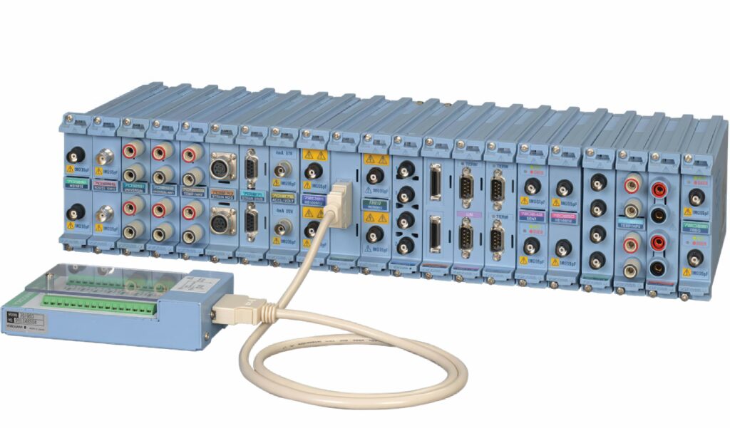
(Image courtesy of Yokogawa)
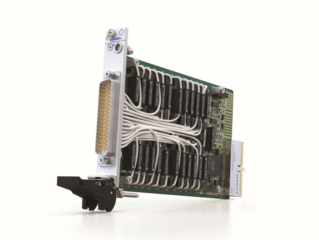
Switching
The demand for testing mechanisms has increased significantly, with high-power transistors and circuitry. This testing requires a source, signals and measurements that need to be routed around a test system.
HV reed relays to 20 kV are used as the basis of test switching systems, from single switches, 1:1 or 1:2 switching or switch-over relays, multiplexers or a matrix. This would have a source measurement unit on one side and the device under test (DUT) on the other side.
Demand is increasingly toward standoff voltages up to 4 kV to test drive systems that run at 1000 V, rising to 1200 V. While the individual components might not go up to such voltages, the system requirement is for higher voltages to deliver more headroom.
Reed relays are popular because they are more robust than electromechanical relays by protecting against back EMF and overvoltages, and have a lifetime of over 1 billion operations at low levels or 10 million operations in harsh test environments.

A key application is in a pre-charge test system for EVs used to isolate the HV battery and low-voltage measurement circuitry. The HV relays are seen as a good choice for slowly charging the system through the relay resistor circuit up to 400 or 800 V before the main contactors are connected, thereby reducing the risk of damage. The small size of the reed relays, down to 4 x 4 mm, means that they can be integrated into the DUT as part of the circuitry and used in end-of-line testing to verify circuit safety.
These systems use the characteristics of reed relays to address complex testing scenarios. In automotive testing, reed relays provide repeatable performance, even under extreme conditions. The versatility of these relays allows them to serve both as protective elements and as functional components in intricate circuit designs.
For example, they can seamlessly integrate into the testing frameworks for EVs, ensuring both safety and reliability across components operating at various voltages. By focusing on advanced materials and engineering techniques, these systems deliver optimal insulation and efficiency, which are vital for sustaining high-density configurations.
Reed relays
and connected via optical transceiver modules
(Image courtesy of Yokogawa)
Reed relays can be used to simulate electrical faults using programmable switching with different signals to create a harsh environment for the ECU or BMS. This approach is used to evaluate what happens when things go wrong, for example, if the battery pack arcs at 1.5 or 2 kV to the BMS.
This can emulate what happens when two cells short and indicate how the BMS might react. If everything is connected through a switch, then a shorting switch in the middle can connect them together to verify a fault and report error codes from the BMS.
Using a reed relay in a vacuum as the HV switch allows for a relay with dimensions down to 4 x 4 mm, which is significantly smaller than the size of an electromechanical relay. The design of the relay depends on the potting material used for insulation and analysis of the heating effects to determine how one relay might impact on another.
For example, a switching system can have 16,000 relays stacked together, meaning that 4000 X points are accessible from any 4 Y points, all in a virtual interface (VXI) form factor, which ensures that there is no hot switching.
Typically, for e-mobility applications, the switching arrays are much smaller (8 x 8, 16 x 16 or 16 x 32) with voltages up to 4 kV routed through the printed circuit board and a hardware interlock to protect the user.
A steel relay for 1500 V is 12.5 mm long in a single-in-line package; for a 5 kV device, it is 24 mm long and for a 20 kV device, it is 58 mm long.
Reed relays are designed for high-density packing with metal shielding in all the relays from one coil to another to maintain efficiency so that they don’t have to work harder to produce the drive for the coil.
The construction uses formless coils without bobbins, providing shorter coil distances that reduce the current consumption. The technology comes from Swiss watch manufacturing that can wrap a coil onto any object, straight onto a glass frame, which saves significant space and means that the relays can be made much smaller.
The coil is created on a metal rod and heated as it turns so that the insulation binds together. The mandrill used to create the coil is the same size as the reed switch, and the coil slots onto the reed switch ensuring that there is no gap between them. This allows more coil windings in the same package.
The relays are 100% tested with functional tests for timing, voltages, contact resistance and HV standoff between the contacts and the coil, so that when the relay goes into the matrix, there is overhead in the testing.
There are also more requests for low leakage switching in GaN transistors for automotive applications. This requires verification of femtoamp leakage to determine whether the GaN transistors are good or not. This level of leakage is achievable through construction of a relay with high-performance potting compounds to prevent leakage. Adding a copper tube as a screen between the switch or the coil, which can be connected to ground or is at the same potential, is called ‘driven guard’ technology and it can help reduce the leakage.
The HV vehicle electrical system must be checked during driving because critical driving situations cannot be represented adequately on the test bench. Additionally, voltage and current characteristics must be measured particularly quickly and precisely to detect even short-term voltage peaks.
The direct effects of driving situations can only be evaluated through real-time analysis of all measurement signals using data from the ECU and intelligent triggers. To realise this, all data from all sources must be synchronised temporally. To accomplish this task, therefore, a perfectly matched measurement system consisting of HV-safe and robust measurement modules, ECU measurement technology and software for measurement data acquisition and real-time analysis is required.
The current and voltage throughout the HV architecture of an EV must be measured and understood at every phase of development, and this includes real operating conditions via field tests. The same rigour is required for the powertrain, the numerous accessory subsystems, converters and power electronics in the vehicle. Even outside the vehicle, external charging infrastructure such as public charging stations and private home wall boxes need to be measured for efficiency and safety.
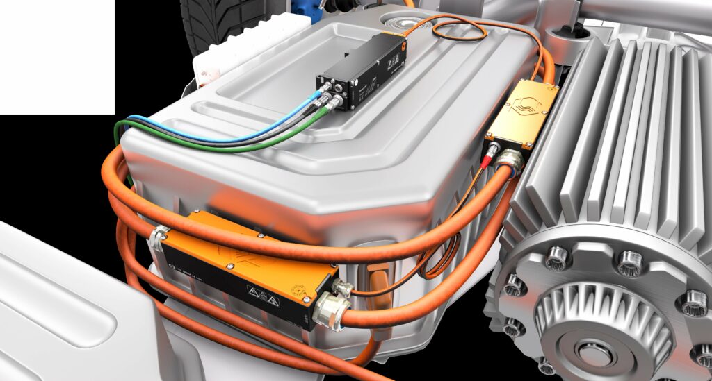
For fast, accurate and synchronised measurements of current and voltage, HV breakout modules offer a simple implementation. The measurements are performed directly in the HV power cables via a plug-in connection within an enclosed module, thereby enabling precise measurements and maximum safety.
An intelligent thermal management system is essential for the efficiency and longevity of EV subsystems. HV batteries, inverters, motors and other components must run optimally to reduce energy consumption and increase vehicle range per charge. These subsystems and their electronic components are within an HV environment (e.g., 400, 800 or 1000 V).
The use of traditional measurement devices is potentially dangerous should the temperature sensor or its exposed cable become conductive. HV-safe measurement technology allows for the use of traditional temperature sensors and thermocouples, such as PT100 and PT1000 sensors or type T, J and K thermocouples, within an HV environment.
Isolation technology and cabling assures the safety of both the user and the system regarding HV modules.
For power measurements, current and voltage are measured synchronously with high temporal resolution at rates of up to 1 MHz within the HV modules. The values are recorded on a measurement computer and processed directly online with suitable analysis software. This software calculates the active power, apparent power, power factor, energy and efficiency in real time for single-phase or multi-phase power measurements for both DC and AC systems.
(Image courtesy of CSM)
Space constrained
A split system can provide high-frequency measurements of current, voltage and power directly in HV power cables, at points where there is insufficient space for breakout modules. Current and voltage sensors can be connected to a split acquisition module via shielded, HV safe sensor cables for distributed installation in test vehicles, even between vehicle components or in cable ducts. Current sensors measure currents via shunt modules from ±10 to ±2000 A and are equipped with a sensor for automatic temperature compensation. Additionally, the voltage is tapped with suitable measurement modules or an HV-safe sensor cable. The modules measure voltages up to ±1000 V, with the measuring range dimensioned up to ±2000 V.
(Image courtesy of CSM)
BMS test
Functional verification is essential for any BMS because it must meet the safety requirements stipulated in industry standards such as ISO 26262.
Most BMS systems comprise a controller and several responder units. The controller unit is responsible for monitoring overall power levels and protecting against overcurrent to and from the battery pack, as well as accepting temperature readings/data from all responder units and controlling safety/contactor switches with all responder units – in case any need to be isolated in the event of overtemperature.
A responder unit is responsible for monitoring the temperature of the cells as well as cell balancing. This ensures that cells connected in series receive the same charge. The most common method of cell balancing is passive (or charge shunting), in which cells that have received their full charge are protected from receiving further charge. Essentially, a resistance is placed in parallel with the cell that needs protecting, which means that most of the current will then bypass that cell to reach and charge others in the series stack.
Verifying that a BMS from a production line is functioning correctly starts with validating the functionality of the responder units within the modules. This needs to simulate cells being charged, discharged and failing.
Central to such testing is the ability to simulate multiple cells at once, but for the test stations to be as compact as possible. Also, test accuracy and speed need to be high and, in this respect, a test time of 15 s per BMS on the production line is the benchmark.
A 750 V PXI 6-Channel Battery Simulator Module provides a suitable basis for the test system. The simulator is effectively a power supply module with six isolated outputs, each capable of supplying up to 7 VDC at up to 300 mA. Each channel can also sink current and therefore behave as a load, just as a battery cell does when being charged.
Each channel is fully isolated from ground and from adjacent channels, allowing them to be connected in series to simulate cells in a stacked architecture. A 750 V isolation barrier allows the module to be used as a lower-power version of a battery stack representative of those used for vehicle propulsion.
Each channel provides independent power and sense connections, allowing the battery simulator to sense a remote load and correct for wiring losses. The battery simulator is designed to respond to dynamic loads, minimising the need for local decoupling capacitors at the load.
A control line on the user connector allows the user to shut down all battery simulator channels with one signal. Multiple control lines can be linked together to provide an easy way of inhibiting the output when using several series-connected modules. This also provides a means of automatic shutdown when connectors are removed.
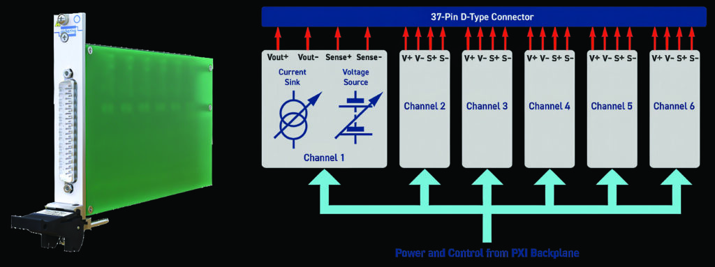
(Image courtesy of MSL Circuits)
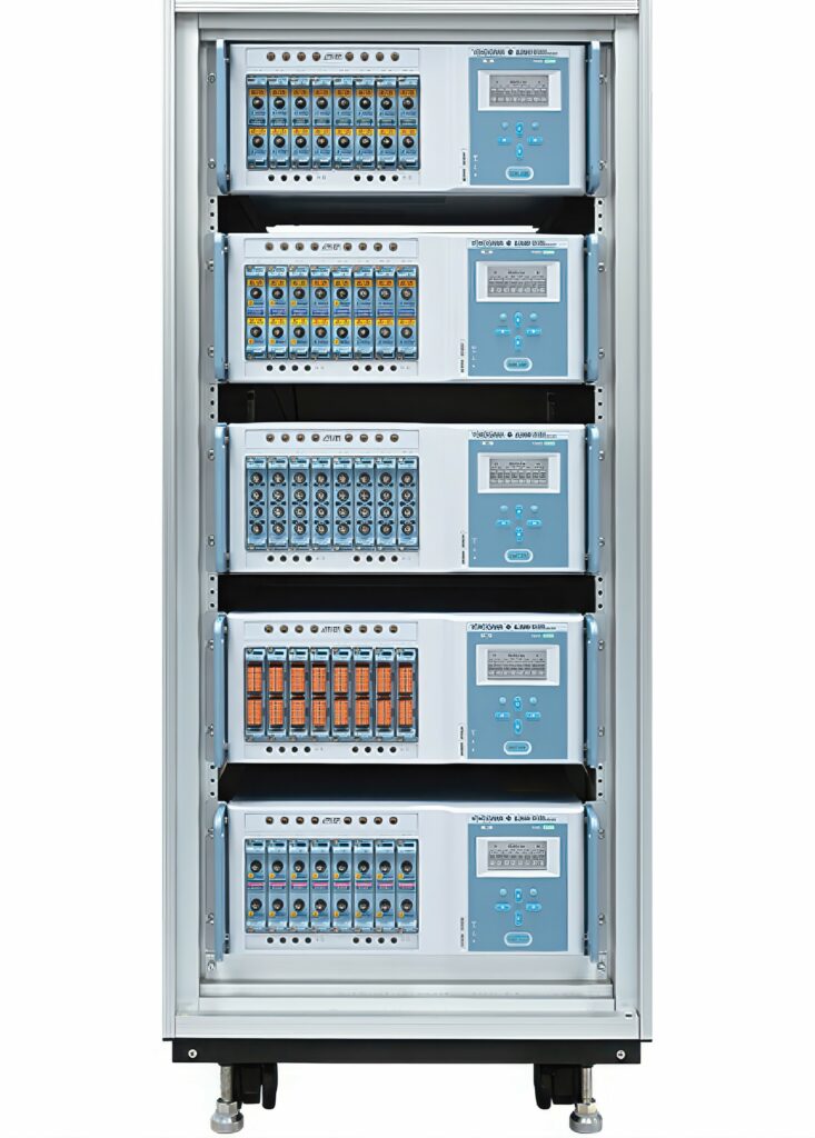
Test environment
A reed relay array was used for a universal BMS test station, capable of verifying both controller and responder units via two VXI fixtures: one for testing controller units and one for testing responder units.
Front end fixtures can be configured for verifying either BMS controller units (up to four at a time) or responder units (up to 10 at a time).
While it would be easier and cheaper to create a back end with a dedicated BMS responder unit test, the reed relay array provides modularity, flexibility and the ability to connect different fixtures. Emulated cell connections are specific to the battery model installed in the fixture. In this way, the test station remains generic with a total of 144 independent battery simulator modules available.
For cell measurements, the simulators are set with different voltages. These are read by the BMS responder and communicated via UART to the BMS controller. A PC connected via CAN bus then compares the recorded voltages against reference ones. It is a relatively simple Pass/Fail test, but it verifies that everything between the cell and the BMS responder’s CAN bus interface is functioning correctly.
For cell balancing, all the simulator card channel outputs are set with different voltages. Then, a command from a BMS controller is sent to the responder units to commence cell balancing, and the balancing current is read by the test station.
Each power module contains a number of thermistors and the responder unit’s ability to read these (under ambient/room temperature conditions) is verified.
Multi-threading allows four cards to be driven at once, which is useful when a single instrument is going to perform the same test on multiple devices. In this case, the test software can interact with 120 simulated cells in just a few milliseconds, whereas single-threaded tests and the use of a slower bus (LXI or GPIB, for example) would take tens of seconds.
Four test stations are used for testing BMS controller units and four for testing BMS responder units, all running 24/7 using the reed relays.
To functionally verify a full BMS (i.e., the controller unit and all its responder units) takes around 60 s. With four test stations available, testing BMSs as they come off the production line at a rate of four per minute (15 s each) has been met.
(Image courtesy of Pickering Interfaces)
Bidirectional test
Testing bidirectional power flow demands equipment that can source and sink power to the converter. Conventional test methods use external circuits and multiple instruments. These methods typically do not allow for smooth signal transitions between sourcing and sinking power, resulting in inaccurate simulations of operating conditions. They also lead to heat build-up in the test environment, requiring costly cooling measures.
Designers are starting to use wide bandgap (WBG) devices with better power efficiency and the ability to handle higher voltages and temperatures than conventional silicon devices. However, their use complicates the simulation and design of DC-to-DC converters. Traditional simulation tools used in the design of power converters do not accurately capture the behaviour of WBG devices and cannot support optimal design of converters using these devices. Therefore, designing today’s converters requires new simulation and test technologies with extra validation and reliability testing to ensure converters will last under harsh operating conditions.
Given the power levels used with converters, designers need to be careful when testing. This requires special safety mechanisms in manufacturing, including redundant systems that do not expose personnel and equipment to HVs if a failure occurs.
However, it is difficult for testers to simulate all the operational and environmental influences on efficiency to evaluate real-world, whole-system operation of the converter. Measuring small percentage changes in efficiency requires instruments with high dynamic range.
Powertrain testing is needed to ensure energy efficiency at the power semiconductor level, through inverter and DC-to-DC converter testing for onboard systems, as well as cell characterisation and power efficiency tests for battery modules and packs, while addressing safety, time and cost concerns.
For the strong (or parallel) hybrid EV (HEV) and the pure EV, an HV bus supplied by a large battery drives the electric powertrain. Power levels of the inverter and motor/generator range from ~ 60 kW to more than 180 kW. Most of the components are bidirectional, allowing power to go from the battery to the inverter, which turns the motor and moves the vehicle (traction drive). When decelerating, the momentum of the vehicle turns the generator, driving power back through the inverter and charging the battery (regenerative braking). Each step of this powertrain requires thorough testing to maximise energy efficiency for the HEV/EV.
from 30 to 810 kW (42 kVA to 1.08 MVA) without need for a transformer
(Image courtesy of Keysight)
Charger testing
Testing DC fast-charging parameters requires sinking very high power to emulate the behaviour of the battery, contributing to high lab overhead costs for electricity and cooling required to dissipate the generated heat. DC fast chargers operate at 1000 V or beyond, with outputs ranging from 15 to 350 kW or higher. EV charge speed depends on the charge rate of the charging station, the maximum power input the EV can handle and the EV’s charging curve. The charging curve tracks how much power it can take over time as it charges.
As DC fast-charging infrastructures are ramping up, emulating an EV battery to test performance and interoperability of the charging station is increasingly important. Testing these high-power systems requires a system that can sink the power offered by the EV charging station, and which supports the communications protocols required to initiate and monitor charging. Software is also necessary to automate DC charging tests using different test standards and parameters.
Testing DC fast-charging stations requires sinking high power loads delivered by the charging station while emulating and monitoring communications with the charging station. Pairing a regenerative DC emulator with a charging analysis system can emulate HV, high-power EV batteries to test high-power DC fast-charging applications up to 1500 V and 900 A, and they can be used in parallel to achieve megawatt-scale solutions.

Acknowledgements
With thanks to Michael Rietvelt at Yokogawa, Noman Hussain and Rob King at Pickering Interfaces.
Some suppliers of HV measurement
Anritsu
AVL
CSM
Emerson/NI
Gantner Instruments
Keysight
Megger
MSL Circuits
Pickering Interfaces
Rohde & Schwarz
Yokogawa
Click here to read the latest issue of E-Mobility Engineering.
ONLINE PARTNERS
