


Connectors
(Courtesy of TE Connectivity)
Plugging the gap
Choosing the most suitable type of connector for an electric vehicle subsystem is governed by a range of factors, as Rory Jackson explains.
Connectors are such vital components in vehicles that they make any explanation of their role redundant. What can be underestimated though are the factors involved in selecting the types of connector needed for different parts of the electrical system. These include resistance to shock loadings and vibration, safety for technicians or operators handling them, and their ease of connection and disconnection. Naturally, their size, weight, power and cost also have to be considered.
Another factor is the growth in the use of electric and hybrid electric vehicles (EVs and HEVs), which has led to growing demand for a diversity of high-voltage connectors.
Road vehicles powered by internal combustion engines (ICEs), for example, tend not to carry voltages above 12 V DC, to feed power to such areas as control and lighting circuits (although 48 V systems are being developed for stop-start motors and turbochargers). But with EV/HEV motors running anywhere from 275 to 800V, and bigger systems such as buses or boats handling even greater loads, shielded connectors rated to carry up to 1000 V are becoming more widely available.
This trend towards high-voltage connectors will continue as hybrid and all-electric powertrains are developed and reach maturity. For example, it is anticipated that container vessels and cruise ships will use complex, 3-11 kV drives.
In addition to feeding higher voltages and currents, connectors for EVs/ HEVs must carry high-speed digital and analogue signals in environments with a lot of electromagnetic interference (EMI). They also need to be designed for safety to prevent arcing and accidental touching of live contacts while being simple to use, which can be unsuitable for high temperatures and large connections.
The low production volumes and high design requirements for connectors in EV and HEV systems (relative to those in fuel-powered vehicles) mean that the cost per vehicle tends to be higher. For example, an ICE-powered road vehicle might contain $32 worth of connectors, whereas for an equivalent hybrid or allelectric vehicle it could be about $75 worth.
In an all-electric architecture, the bulk of the current handled by connectors is between the electric motor, the battery pack, the charger unit and the electronic power converter. A hybrid power architecture might contain around 25% more connectors to account for the presence of an engine and/or generator, as well as additional clutches and control units throughout the drivetrain.
Alongside high-voltage connectors, auxiliary ones such as high-pole connectors for control units, low-pole connectors for sensors and actuators, and terminals for signal transmission must also be accounted for, remembering that modern processor systems consume more power than their predecessors.
These contribute further to the criteria that EV and HEV connectors must follow for power handling, mating/unmating cycles and ruggedness during operation. Connector requirements should therefore be determined early in the design process.

Metals
Copper and aluminium are the most common conductor materials. While copper is the international standard, aluminium weighs only 30% as much (with 61% the conductivity). As a result, a bare aluminium wire (of equivalent total conductivity to a given bare copper wire) will be thicker but weigh half as much.
The price of aluminium conductors is also generally lower than copper ones, making them ideal for cost-constrained applications as well as weightsensitive vehicles such as consumer automobiles or electric aircraft.
Between the connector and the conductor comes the choice of how to join the wire to the terminal. Crimping is perhaps the most well-established method, and is commonly used with copper. In this method, mechanical force is applied, typically with a specialised handheld crimping tool, to ‘cold-weld’ the conductors inside the terminal body.
A crimped connector should be inspected before use to ensure the right amount of force has been applied. Too much and the wire insulation might be pierced or pinched in places; too little and the ‘crimp legs’ on the terminal body might not be tight enough, potentially leaving the connection vulnerable to shock loading or vibration.
While a correctly soldered connector can prevent failures just as well as crimped connections, crimping is generally preferred over soldering. That is because crimped connectors have a longer history of use and are thought to resist vibration better. Crimping is also the faster, simpler method, without requiring the application of heat or any particular safety equipment.

(Courtesy of Baumann)
For aluminium conductors, however, crimping does not typically provide enough compression to enable contact resistance. With a melting point more than 400 C higher than copper, and commonly larger wire cross-sections, it is more usual to weld aluminium in order to provide a reliable, permanent bond with the terminal.
Then there is the issue of fretting corrosion. This occurs when the male and female connector interfaces move against one another, typically when they are subjected to repeated vibration and loads. It can also be caused by excessive heat in the connector, which leads to repeated thermal expansion and contraction, and again micro-motions between the contacts.
If fretting corrosion does occur, the wear and tear on the contact surface reduces the area of metallic contact, so the electrical resistance across it rises significantly. In a vehicle’s powertrain, that may mean generating excessive heat, which could cause thermal runaway by accelerating the rate of fretting corrosion and increase in resistance.
The corrosion can also cause arcing or micro-arcing, creating burns on the contact surface and also resulting in thermal runaway. If left unchecked, either condition can eventually cause the connector to degrade until the drive system fails.
Signal connectors can also be affected by this corrosion, leading to erroneous readings from analogue systems such as sensors or audio systems, or errors and slower data throughput in high-speed digital systems in the vehicle.
In-depth testing must always be conducted for signs of fretting corrosion, as it can be unpredictable between different contact geometries, materials and loads.
Careful selection of metals for plating can be useful for mitigating the corrosion. The use of thicker gold or palladium alloys (or silver, which costs less) can be ideal for providing a denser barrier against fretting corrosion of the copper or aluminium underneath (as opposed to ‘fretting wear’ of the plating, which is less of a problem).
Tin in particular is notably susceptible to fretting damage and therefore has limited use in electrical contacts. The tendency for tin to ‘whisker’ and cause short-circuits in press-fit signal connectors has spurred interest in alternatives, including bismuth-plated pins.
Tests indicate that bismuth-plated contacts ‘whisker’ at less than 1600 times the rate of tin, and as a nontoxic material with one-tenth of tin’s conductivity, its use in supplying safer signal terminals is expected to rise.
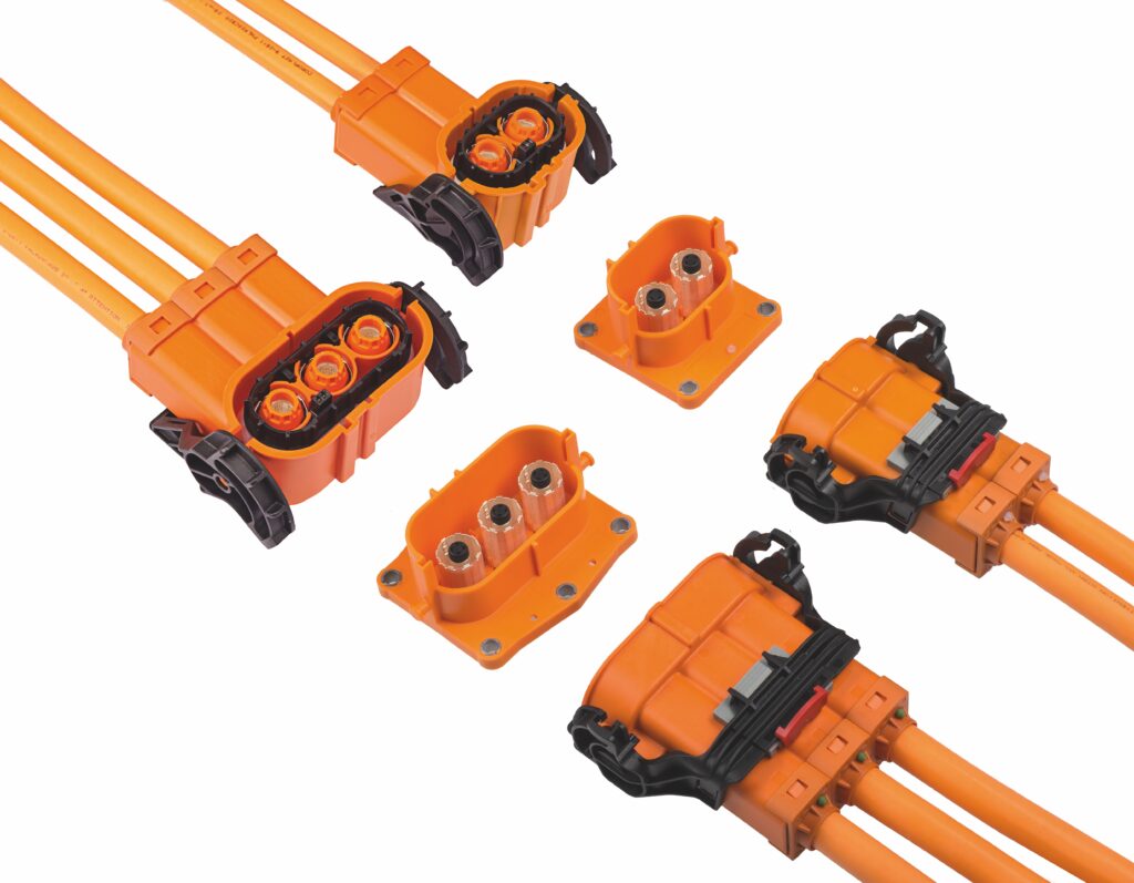
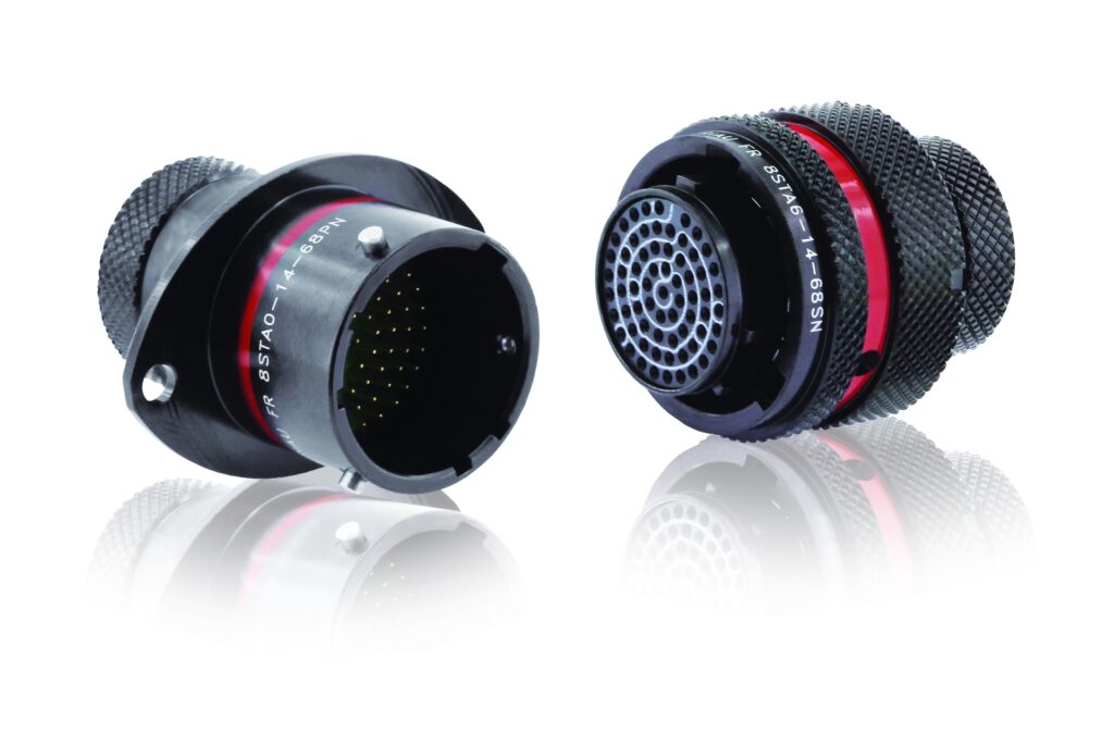
High-voltage connectors
To prevent fretting corrosion, not to mention the dangers associated with the accidental unmating of powertrain connectors, security and stability are imperative in high-voltage connector designs for linking batteries, motors, DC-AC inverters and DC-DC converters. They therefore differ in some ways from low-voltage designs.
Generally, anything above 60 V is considered ‘high voltage’ to the point that precautions must be built in to make the electrical contacts ‘touchproof’ or finger-proof. As a result, high-voltage connectors have noticeably higher walls around the connection points than in low-voltage designs to prevent accidentally touching a live part.
to minimise the chances of accidental touching of live contacts during disconnection
(Courtesy of TE Connectivity)
All-round (360º) EMI shielding of the connectors is also necessary in order to mitigate the influence of the highpower circuits on nearby electronic components.
Terminals often slot into isolated cavities to lower the chances of short-circuits between two or more of them, with greater creepage (the minimum distance along the surface of a solid insulating material between two conductive parts) and clearance (the minimum distance in air between two conductive parts) separating the terminals compared with connectors from other categories. Environmental sealing must also be built in, to protect against such issues as moisture or heat build-up.
Judicious use of plastics is necessary for making high-voltage connector housings, as well as providing appropriate electrical insulations for preventing arcing or cross-conductivity. The ideal plastic should be matched to the vehicle’s application according to factors such as voltage, current, altitude or pollution level.
The growth of the EV/HEVs market has also prompted greater use of connectors with highly heat-resistant plastics. Grades of polyamide and polybutylene terephthalate are often used in high-voltage connections for their flame retardancy and electrical isolation qualities.
In addition, these polymers are colour-stable. High-voltage connectors are generally colour-coded bright orange to make them easily identifiable by technical staff. The ability to resist thermal ageing and to keep their colour and shade for at least 10 years is a key requirement here.
High-voltage connector classes can be divided according to their currentcarrying capacity and wire crosssections. At the lower end of the scale, where relatively few kilowatts of power are needed – in an onboard charging system, for example – there might be connectors designed for 20-30 A, with conductor cross-sections of up to 3 or 4 mm, potentially with a voltage range up to 600 or 700 V DC.
For something more heavy duty, such as a DC-AC inverter, a step up in the current and wire diameter could be necessary. Connectors for this type of application tend to work with wires up to 6 mm thick, and with current capacities from about 32 to 40 A, on voltages from 750 to 850 V DC.
When moving into electric and hybrid powertrain connectors, automotive vehicles can require current-carrying capacities of 200 A. The wires here can vary widely in cross-section, from 25 to 50 mm (as vehicle manufacturers opt to replace copper power cables with thicker aluminium to save weight), and DC voltages can run as high as 850 V or as low as 650 V.
For anything larger, such as electric buses, lorries or boats, connectors must carry 300 A, while integrating wires up to 75 mm in diameter.

The process of securing or latching powertrain connectors tends to be approached with unmating as a multistage process, to help ensure that technicians cannot inadvertently grab a high-voltage cable to pull it out. Often that means including a lever around the connector plug to lock the connection in place.
Naturally, EV and HEV manufacturers may instead opt for a connector that ‘screws in’ rather than purely ‘mating’. In practice, that tends to mean two to four fasteners bolting the male and female connectors together (the number typically rises with the size of the connector system and the number of contacts).
Being held in place more securely, a screwed-in connector gives the advantages of better contact resistance, lower losses and greater tolerance to shock and vibration. Of course, installing them with the correct placement and torque (as well as disconnections for maintenance, repairs or other purposes) will be more time-consuming and labour-intensive, potentially driving up production costs.
Also, if the mating cycles at a particular branch or junction of an EV’s powertrain are expected to be on the high side, then screw-type connectors could be more bother than they’re worth.
Battery connectors are a notable example of the advantages of stepbased latching systems accompanying high-voltage connectors. Manual service disconnect (MSD) mechanisms are a common offering from connector suppliers, and are aimed at securing a battery pack in place against shock loads and vibrations that might force its connection to come loose.
Usually consisting of a two-stage lever integrated around the pack, it is a tool-free alternative to fasteners, saving time, labour costs and potentially weight, as the MSD tends to be made from plastic rather than metal. The ability to do this, however, can be constrained by how much space is available inside the vehicle, around a given receptacle, to fit a bulky latching system in place.
Again, connector types must be considered early in the design process, so that suppliers of motors, inverters and batteries can be notified as to whether bolted or mated connector receptacles will be needed.
(Courtesy of Amphenol Industrial)
Some connector types for highvoltage powertrains have taken the ‘screw’ concept and re-applied it by constructing a hyperbolic socket, which distributes forces such as friction over far more of the mating pin surface than typical designs. This makes mating/unmating much easier, and improves vibration resistance while also reducing damage from fretting corrosion.
EV and HEV manufacturers can also opt for a high-voltage interlock loop (HVIL) or circuit. This is a voltage and current loop mechanism designed to detect any tampering or opening of high-power connections.
HVILs are typically integrated into every high-voltage component, such as the onboard charger, DC-DC converter and most importantly the battery, as by intelligently monitoring the HVIL signal, the battery can quickly turn off the high-voltage power contactors. Also, if an HVIL becomes broken, owing to a malfunction for example, the battery will again switch off the power relays.
The use of HVILs and their signals can also ensure that all connectors are secured properly before an EV/ HEV power system is started up, and help to prevent arcing during disconnection.
Including an HVIL in the connector system tends to mean adding two signal pin interfaces to the housing, as well as potentially integrating a shunt to mate and close the interlock circuit separately from the high-voltage power terminals to prevent transfer of high current (and thus prevent arcing during mating/unmating of the power connectors).
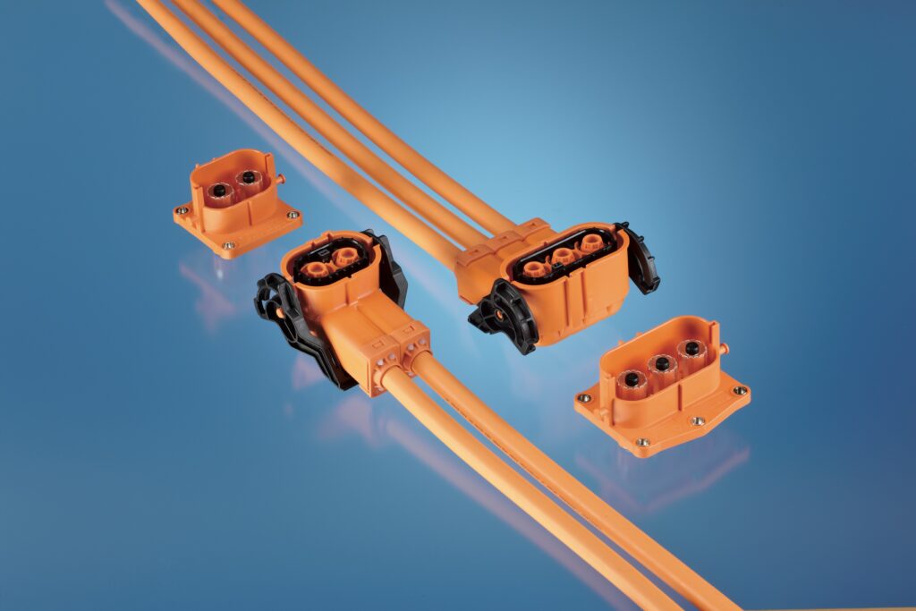
(Courtesy of Phoenix Contact)
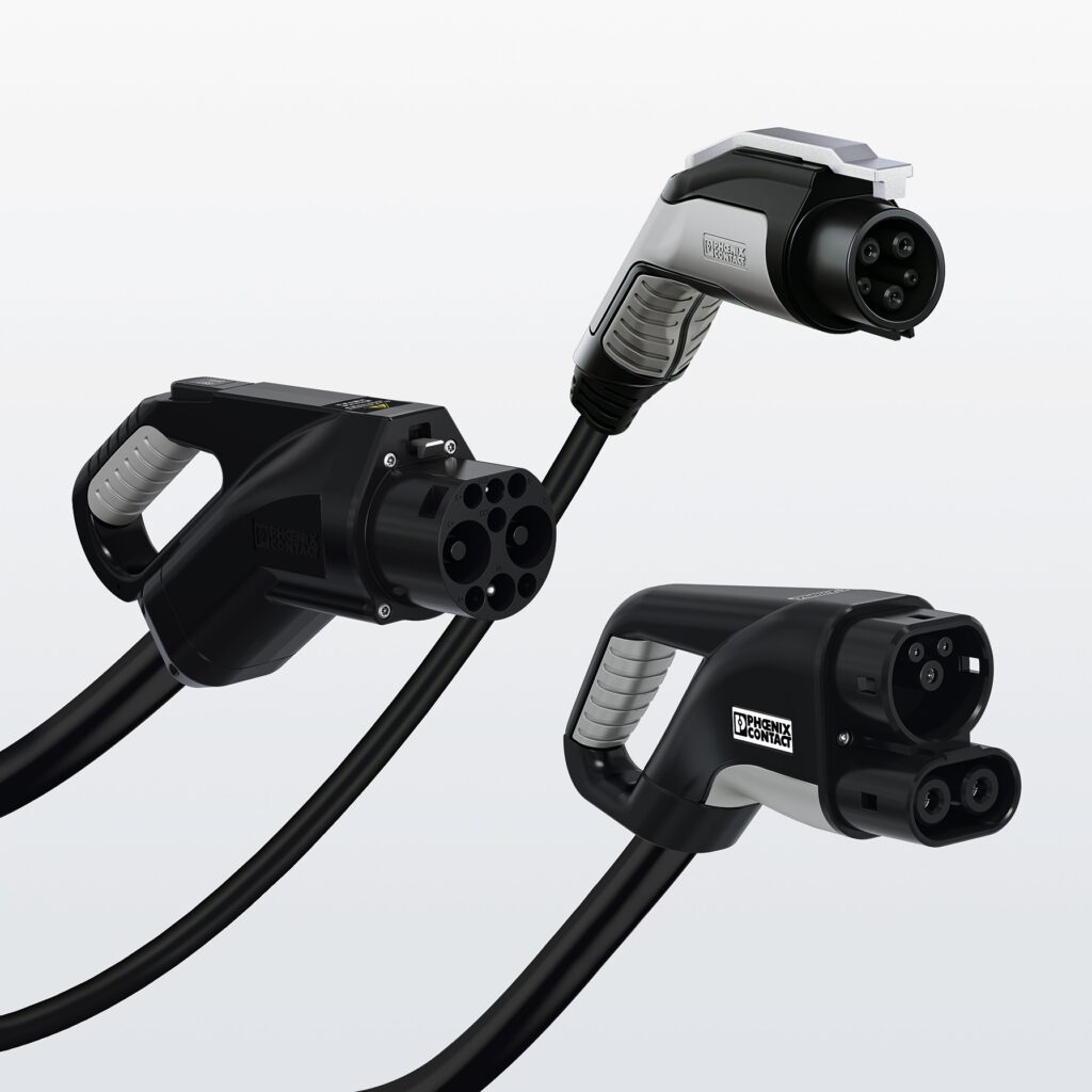
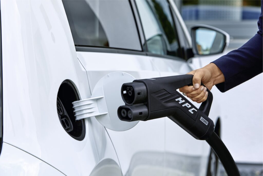
Charging connectors
Charging ports also need to be considered for electric and plug-in hybrid vehicle connectors. There is a range of standardised classes for the male plugs and female sockets, which can be divided according to charging speed, whether it charges using AC or DC power, and its ‘Type’ (as defined by the IEC/EN 62196 standards for conductive charging of electric vehicles).
The Type 1 connector is common in Japanese and American road vehicles, and incorporates five pins – one for delivering main power, one as a neutral or secondary power pin, one for earthing, a proximity pin (which acts similarly to an HVIL) and a control pilot pin (which communicates data between the charge point and the vehicle). A clip for latching is also a typical feature.
German car makers developed the Type 2 connector to allow threephase AC charging, and as a result the standard comes with two extra power terminals rather than one (for a total of three). However, as not all vehicles with Type 2 charging ports use three-phase charging, these may be superfluous.
Type 2 connectors also typically integrate an earth pin, a neutral pin, a proximity pin and a control pilot pin, for a total of seven.
For consumer electric vehicles designed to be charged solely at home between journeys, a 3 kW Type 1 or Type 2 charger might be integrated. Despite the description, these tend to receive charge at a maximum of 3.3-3.6 kW (as they can be rated up to 16 A).
For vehicles designed for longer use around urban areas, where fast charging at public stations within one to five hours is desirable, Type 1s and 2s are still common, especially among Asian and European car brands respectively.
However, these variants will be designed for 7 kW (single-phase charging) or 22 kW (three-phase). A 7 kW charging point will fully recharge a vehicle in three to five hours, while a 22 kW charger will take an hour or two. This assumes compatibility with the vehicle’s onboard charging receptacle though, as a 3.6 kW charging port will still take six to 12 hours as it can only draw up to 3.6 kW.
Vehicles such as electric or hybrid buses or trucks should be designed with the rapid charging connectors found on motorways or retail parking zones. A car charging at such a point will typically regain 80-100% of its total power within an hour.
These types of charging points might use a 43 kW Type 2 interface for AC, as well as a few key types for DC charging. The Japan Electric Vehicle Standard (JEVS 6105) connector, or CHAdeMO, is used in rapid charging points for some Asian vehicles up to 50 kW.
This configuration uses nine pins across four terminals, with a 9 mm diameter pin for DC (+), and another for DC (-). The other seven pins have 1.6 mm diameters and are used for checking the connection, grounding, controlling the charging relay and for communicating critical data such as maximum voltage and current parameters via CAN bus.
The other standard rapid DC charging connector series is the Combined Charging System (CCS). This comes in two versions that are similar to the Type 1 and Type 2 connectors, except with the addition of two pins, one for DC (+) and one for DC (-), to both configurations.
The CCS1 (Type 1 with two DC pins) thus has a total of seven pins, to be compatible with Type 1 AC charging stations and rapid DC charging stations up to 125 kW, and is designed for 200 or 500 V DC vehicles from the US or Japan, and for communicating via PLC rather than CAN.
The CCS2 (Type 2 with two DC pins) receptacle features nine pins, to be charged by Type 2 AC chargers or 200 V (or 850 V) DC rapid chargers in the EU or in the rest of the world at up to 170 kW. The rapid charging plug, however, has only five terminals, for DC (+), DC (-), earth pin, proximity pin and the control pilot pin.
Also suitable for fast DC charging is the Chinese GB/T connector, a nine-pin standard which, in addition to DC (+) and (-) ports, two CAN ports and an earth pin, also features two connection confirmation signal pins, a positive low auxiliary power port and a negative low auxiliary power port.
(Courtesy of Phoenix Contact)
Data connectors
While EVs are perceived as being electrically and electronically simpler than fuel-powered vehicles, thanks to their simpler powertrains, they still come with a growing variety of features that raise the low-voltage connector count inside each chassis.
Flows of information from safety features such as cameras and sensors around the vehicle, as well as power monitoring and analysis systems, are all contributing to a rising number of high-speed data connectors in electric and hybrid vehicles.
To handle the protocols for all this data, vehicle manufacturers might choose between an Ethernet or a coaxial RF connector.
While coaxial systems cost more, they can provide data throughputs up to 12 Gbit/s compared to the 1 Gbit/s typical of Ethernet. On the other hand, if an EV uses sufficiently powerful processors, they may be able to perform enough analysis without needing the level of data provided by coaxial cables, in which case Ethernet should meet connection requirements.
Coaxial connectors can also use a wider range of available fastening mechanisms, including bayonet, screwthread or blind mate. While this will add cost to the vehicle, it will make invehicle data links more secure without requiring tooling or space for bolts around the connectors (which will be increasingly limited as EVs’ electronic subsystems become more numerous).
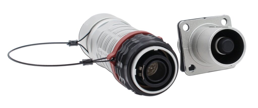
(Courtesy of Souriau)
In addition to the rising use of Ethernet and coaxial connectors, FAKRA (Facharbeitskreis Automobil) RF connectors remain a popular standard for comms up to 6 GHz. While not quite covering frequencies up to 9 GHz, as coaxial RF connectors do, FAKRA is still often used in GPS antennas, engine management systems, navigation systems and other critical subsystems.
They also come in a lightweight plastic housing with a secure locking mechanism, enabling comparable locking yet easier disconnection than coaxial designs.
The emergence of distinct standard models for charging connectors from Europe, the US and Japan means vehicle manufacturers must consider the geographical market for their EV/HEV, as well as the likeliest maximum charging speed before receptacle integration.
And with alternative technologies such as wireless charging and electrified roads remaining unclear as to charging speed, logistics, costs and other factors, charging connectors are likely to continue to be crucial EV and HEV components well into the foreseeable future.
Acknowledgements
The author would like to thank Dominique Freckmann from TE Connectivity, Frederik Effenberger from Phoenix Contact, Sandrine Le Corre from Esterline, and Melanie Tropper from Baumann for their help with researching this article.
ONLINE PARTNERS

