


Cables
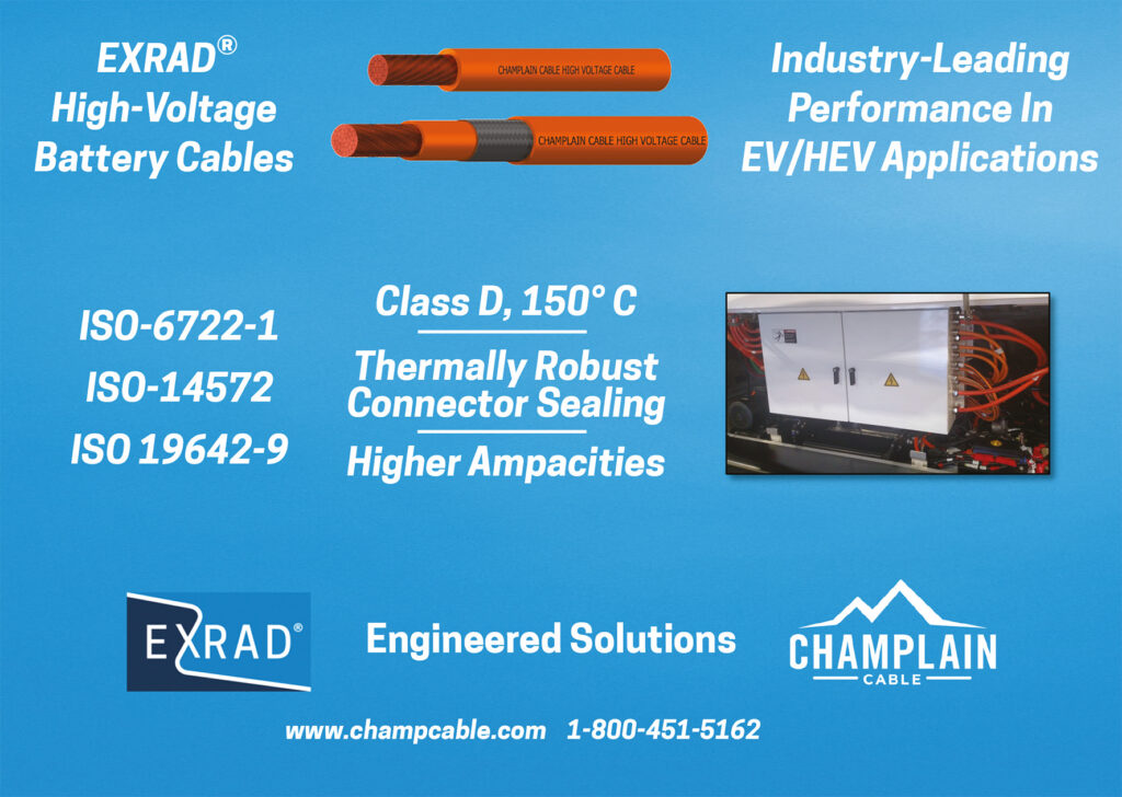
Great care should be taken to model the internal characteristics of electric and hybrid vehicles in order to determine the optimal configurations and routes the cables should take
(Courtesy of Champlain Cable)
There is a complexity to producing cables for EVs that some may find surprising. Rory Jackson has the details.
Down to the wires
The importance of cables for channelling power and data throughout electric and hybrid vehicles over thousands of hours cannot be overstated. However, before selecting and specifying cable requirements, the mechanical stresses they are likely to face – along with temperature requirements, chemical tolerances, EMI levels and other factors – must first be accounted for.
Depending on the vehicle, its operational profile and the specifications of the cable in question, various design simulations and testing techniques might be carried out. These are often required to certify key performance characteristics of the cables, in accordance with UL and NEC standards for charging, and SAE and ISO standards for internal cables.
And while there is a certain universality in terms of the quality of copper material or winding processes, there are many different materials and approaches that can be taken to insulating and shielding each conductor according to its application.
High-voltage insulation
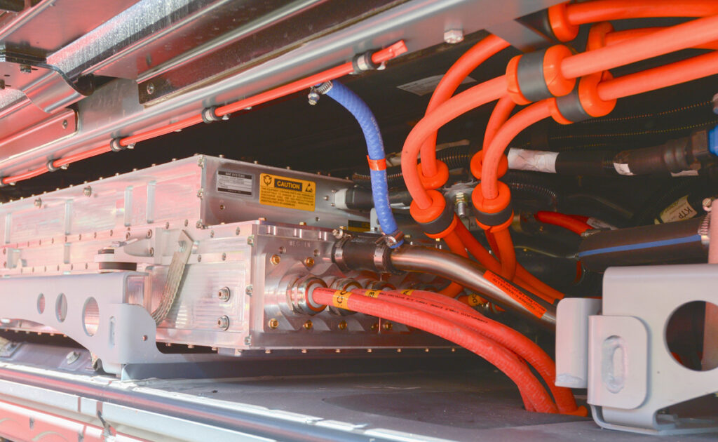
Cables running internally through vehicles can generally be divided into two voltage categories – low voltage, between 0 and 60 V, and high voltage, which typically means anything above 60 V (and typically running up to 600, 800 or as high as 1500 V in the e-mobility sector).
The key reason for this distinction is safety. Human contact with anything higher than 60 V is generally considered to be lethal (although any wire or cable’s lethality can be increased by factors such as the health of the individual, the amount of current going through the conductor, or if it is a DC connection rather than an AC supply).
Standards therefore require that the outer jackets of high-voltage cables are coloured in recognisable orange to make this danger easily identifiable to the vehicle’s owner, technicians and safety responders at crash sites.
To protect people and surrounding components from electricity supplies at ever-higher voltages, a vehicle designer may opt for thicker insulation. This can reliably provide for higher electrical performance, although it can increase material costs and make the cable heavier and stiffer, and therefore harder to route through a vehicle.
Different materials provide different levels of insulation. One of the main standards by which these can be differentiated is according to their required temperature rating.
For example, fluoropolymers are widely used across the industry for high-voltage, high-temperature applications. These include ETFE (ethylene tetrafluoroethylene) and FEP (fluorinated ethylene propylene), both of which are rated to 155 C. PFA (perfluoroalkoxy alkane), another fluoropolymer, is rated to 180 C, although it has also been found to show normal performance at 250 C.
Silicone rubber jackets are also popular, and for EVs they are typically rated to up to 180 C, although they can be formulated to operate at higher temperatures. EPDM (ethylene propylene diene monomer) rubbers used in EV and HEV cables can be formulated to perform up to temperatures from 100-150 C, and potentially higher depending on the application.
Different suppliers have varying recipes and approaches to altering performance characteristics such as the temperature resistance of their insulation polymers. That largely means starting with the basic polymer and adding ingredients such as antioxidants for increased heat-ageing capability.
A cables manufacturer might also add anti-ozonants, for instance, to protect ozone degrading the material, which is a common concern in highvoltage environments.
However, a range of other specifications and performance characteristics of the insulation must be considered, many of which are tied inextricably to which polymer is used and which cannot be significantly altered regardless of reformulation.
Perhaps most important, the electrical resistance of a given material can generally only be increased by adding thickness (and these factors tend to rise in direct proportion with each other). But if a cable’s insulation is too thick it becomes inflexible and therefore problematic to route through the body of a vehicle.
EV designers should also consider how a given material works in different chemical environments. For example, silicones are widely used for high-voltage cables in electric and hybrid vehicles without issue. They are extremely flexible, give ideal performance at high temperatures, and resist damage from a wide range of chemicals.
However, they are at risk of failure when in contact with strong battery acids. If a battery pack’s sealing has failed, that could cause considerable damage to nearby silicone-insulated cables.
Silicones can also be mechanically weaker than some other insulation materials. That might cause problems if they are routed among a number of powertrain components that have sharp edges, which could eventually tear through the rubber and damage the conductor inside.
Increasingly, manufacturers are also wary of using silicones (and similar rubber compounds) because of concerns about outgassing. The substances released from rubbers during outgassing can harm other electronics in a vehicle by condensing onto enclosures and leaking into them if triggered by exposing the siliconebased insulator to heat, such as during shrink-tube applications or ultrasonic welding.
The probability of outgassing and of other chemical or mechanical malfunctions can be reduced by having the insulating material (such as silicones or others) extruded and thermally set in a curing vessel. This ensures that, unlike a thermoplastic, the newly made thermoset insulation will never melt again, enabling it to endure a variety of conditions and remain intact.
Alternatively, some cables in EVs are insulated with polymers that use irradiation cross-linking. In this process, an electron accelerator produces a stream of electrons with enough energy to remove hydrogen atoms from the molecular chains of the thermoplastic.
The affected points of the molecular chains can then form carbon crosslinks with each other, locking many molecular bonds in place and turning the thermoplastic into a thermoset.
That makes irradiated cross-link polymers more stable dielectrically and physically, alongside other benefits such as temperature ratings from 150 to 225 C and higher abrasion resistance than many rubber materials.
The greater dielectric stability of irradiated cross-link polymers and EPDM (compared with thermoplastic elastomers) allows cables to be made with thinner insulation walls without risking the material being punctured or damaged by high voltages. Thinner walls are increasingly preferred by vehicle manufacturers owing to their advantages in terms of weight saving, routing and handling, for example.
Insulation materials should also be checked for their rated lifetime. The longer that is, at a given temperature rating, the longer the interval between a vehicle needing maintenance and possibly replacement of cables.
The ISO 6722-1 standard, for example, specifies 3000 hours of heat age-testing at a given temperature. As that temperature will invariably be an extreme for the vehicle environment, a qualified material should then last tens of thousands of hours before having to be replaced.
More hours may be required though for vehicles such as buses and utility trucks, but cable developers can provide for that as well.
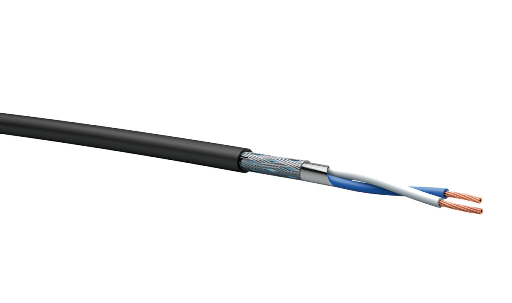
Shielding
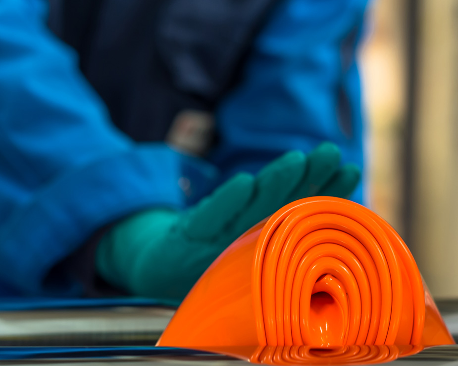
(Courtesy of Elkem)
As cable voltages increase, vehicle integrators also need to consider the side effects on the surrounding systems. Electric and hybrid vehicles using high-power electric motors with pulse width modulation (PWM) systems, for example, can be at particular risk from the electromagnetic ‘noise’ generated by high-voltage cables, as the wiring can act as an antenna and radiate that noise throughout the vehicle.
This EMI can disrupt the signals controlling the onboard motors for traction and other mechanical systems. And as vehicles become ‘smarter’ – with more and more sensors, computer processors, RF systems and connections installed across their architectures – so the need for shielding becomes safety-critical.
As a result, cables for electric and hybrid vehicles can range from relatively simple single-insulator designs to those with more than one level of insulation, with a braid or shield integrated to reduce EM emissions, and a jacket covering that.
That greatly increases cable complexity and thickness but reduces mechanical flexibility, which raises additional considerations regarding costs, routing, packaging and usability within the vehicle.
However, when working with high voltages in sensitive areas of a vehicle, there can be no accidental EMI or formation of electrical arcs, as that would be destructive to vital system functions.
EMI protection is not needed in all areas of the vehicle though. For example, cables delivering stable DC power from the batteries, in an early ‘leg’ of the powertrain, might not need shielding.
However, as indicated, electric motors using PWM generate a lot of EMI coming from them and therefore require shielded cables. That goes for any device with an inductive feedback and varying frequency.
Also, if high-voltage cables are placed near critical safety circuits for items such as proximity sensors, they must be shielded to prevent that safety information from being corrupted. And an autonomous vehicle using GNSS signals for position updates must also keep its satellite receivers and related cables protected.
The exact nature of the protection can vary, for example by using a braid. This is made from a weave of metal strands around the insulation layer.
Typically, tin copper is used as a braid material for its corrosion resistance qualities, although aluminium is becoming popular thanks to its light weight relative to other metals. Aluminium can be challenging and costly to work with, however, given its propensity to oxidise freely in air, making it difficult to form connections with it.
A metal foil layer (typically aluminium) can be used in place of a braid, and that provides 100% physical coverage for EMI shielding across the cable area. Braid coverage is typically between 70% and 95% of a cable, which can be enough for cables running past non-essential electronics, but some standards increasingly require minimum coverage of 80% or even 95% to certify the integrity of a vehicle’s systems.
That means the 95%-coverage braid has smaller gaps and more metallic material than the 80% and 70%-coverage braids, adding size and cost to the cable (and reducing flexibility) without necessarily increasing the working effectiveness of the shielding. A vehicle integrator should therefore analyse their vehicle systems’ protection (and certification) requirements carefully before determining the optimal configuration for their needs.
The other key difference between a braid and a foil is that they work in different frequency ranges. However, in areas of a vehicle with broadband frequencies or multiple electronic systems working on different frequency bands, cables can be manufactured with both a foil and a braid integrated, sandwiched amid layers of insulation.
That can be particularly important in parts of a vehicle that will experience regular higher spikes of current, where vehicle designers need to assure subsystem integrity in terms of the vehicle’s ability to operate without being affected by EM noise.
Low-voltage cables
(Courtesy of Acome)
Automotive electronics for systems such as radio, air conditioning, sensors and so on are increasingly being designed as 48 V systems, replacing the traditional 12 and 24 V architectures. Although that level of power is far lower than the voltages associated with batteries and traction motors, it still causes a lot of concern, as the design requirements of the vehicle become more stringent.
For example, a 48 V system needs far greater attention to corrosion resistance, arc resistance and safety than a 12 V one. While 48 V may be deemed ‘low voltage’ compared with battery cables for example, a 48 V DC connection is still powerful enough to cause fatal injuries.
In relative terms, a 12-48 V cable can be made using less expensive materials and designs than a high-voltage cable, without risking safety, EMI and so on. For example, the use of an off-centre cable is undesirable in high-voltage applications as the noise and heat emissions can be unevenly distributed, and more electrical pressure is put on one side of the insulation than another. In a low-voltage cable, however, this is less of a problem, and an off-centre cable can still be used.
Alternatively, imperfections in the insulation, such as an uneven dispersion of some ingredient or particle, or a mechanical flaw, will probably not develop into a problem in a low-voltage cable. In a high-voltage cable though, such imperfections are highly undesirable given the greater risks at play.
The lower levels of electricity, heat and EM emissions from 12-48 V cables also mean they can use less costly insulation materials, such as PVC or other thermoplastics, as the chances of melting and the risks posed by conductor exposure are lower. The use of thermosets would run far in excess of the insulation requirements of such wires, and make these otherwise thin wires pointlessly thick and difficult to route.
Higher frequency connections, such as those for advanced sensors in safety, autonomy or performance monitoring applications, are using ever-thinner cables. As operating frequencies run in excess of 1 MHz, vehicles are being designed to use wires thinner than 48-50 AWG (0.03160- 0.02504 mm).
Such diameters are extremely challenging to produce reliably, as they require high-precision machinery and tension control. They can also take only grams of tension before breaking.
A single wire working at very high operating frequencies might also be prone to losses. The skin effect, in which AC density tends to be greater near the surface of the conductor, causes the conductor’s resistance to increase with frequency, reducing the effective cross-section of the wire and causing those losses.
Proximity to other conductors carrying AC power in the same direction can also ‘crowd’ the current, driving up resistance with frequency and causing further losses that could disrupt system performances across an EV.
Developers of EVs and HEVs can therefore opt to use specially woven litz wire, which is made of multiple strands of enamelled magnet wires bunched or stranded together, for their highfrequency applications. Compared with typical winding wire, litz wire reduces operating temperatures and losses by distributing current among multiple, independently insulated strands. It also has greater mechanical flexibility than a single solid wire of the same diameter.
Charging cables

(Courtesy of Rubadue Wire)
Litz wire is also useful for charging applications, given that it reduces losses at high frequencies for AC, as well as when using DC. Specifications for charging cable types are set out in UL and NEC standards, and allow for some variation in conductor and insulation selection.
For example, type EV charging cables are rated to 600 V, and contain two or more 18 AWG (1.024 mm) or 240 mm2 thermoset-insulated conductors; they can also integrate one or more insulated grounding conductors.
Type EV cables can carry hybrid data, comms or fibre optic cable in any AWG size as well.
Type EVE and EVT cables are the same as type EV, except the former uses a thermoplastic elastomer instead of thermoset insulation, and the latter uses PVC.
For 300 V charging cables, NEC and UL standards specify the use of type EVJ cables, which contain two to six 18-12 AWG (1.024-2.053 mm) thermoset-insulated conductors, as well as one or more insulated grounding conductors.
Types EVJE and EVJT are the same as EVJ, but use thermoplastic elastomer insulations and jackets, while type EVJT is insulated with PVC.
The standards also specify nominal insulation thickness. For types EV, EVE and EVT, the material thickness can range from 0.76 to 2.41 mm, with the degree of insulation going up with the diameter and volume of the conductors. The 300 V types are all nominally specified to have walls that are 0.76 mm thick.
The standards also dictate that all these charging cables must have oil-resistant outer jackets, be usable in wet environments, and optionally incorporate Nylon in their insulation, as well as shielding if desired.
Before the cables can be certified, they are sent to UL to be tested. This will look at areas such as crush resistance (for example, if a vehicle runs over the charging cable) and other forms of mechanical performance, as well as aspects of electrical performance and chemical resistance.
On top of adhering to standards, developers of vehicle charging points should consider ease of use when selecting or speccing a cable. If the charger cable is not flexible enough, it could be difficult for some individuals to handle and plug them into their vehicle, which could cause minor damage to the vehicle or injury to the user – and flexibility is not covered by the standard.
Quality control
(Courtesy of St Cross Electronics)
Standards such as ISO 6722-1 define a wide range of tests that vehicle wires and cables must pass for certification.
Spark testing is important for ensuring fault-free insulation. This is carried out by running a cable through a curtain of metal beads that have been energised to a particular voltage, as given by the standards (and these can run up 10,000 V or higher). A spark-out will occur if there is a fault somewhere along the insulation, which can then be located and removed before shipping.
Diameter measurement tests are run using dual-axis laser sensors, to check that the cable stays within specified physical size limits. Depending on the wire or cable, the tolerable margins on their sizes can run as tight as 0.05 mm.
Also, the insulation should face two main tests for abrasion. One examines the material’s tolerance to contact with grit and dirt, and involves using a piece of sandpaper in a reel-to-reel tape mechanism (or similar) to rub against the cable’s outer wall. The team carrying out the test then records how many millimetres or centimetres it takes to abrade through the insulation.
The other test examines scrape insulation, which is important for routing cables through vehicles and judging how well the material can tolerate forced and repeated contact against sharp or protruding metal surfaces.
In this test, the conductor is slightly energised by a piece of metal being rubbed back and forth across the insulation, and when the wire shorts out, the test stops and the cycles or millimetres taken to breach the cable wall are recorded.
Similar tests can be conducted for pinching and crushing the insulation, to account for how vehicle motions or accidents might affect cables.
Testing the chemical tolerances of cables is also vital, and the range of such tests can vary between companies. At the most basic level, a company should test for water and battery acid as two of the most common fluids that a cable might come into contact with. As mentioned, however, some standards and situations require that cables must also be oil-resistant, despite battery-electric vehicles not necessarily needing very much oil.
Companies might also want to test their cables for how they handle contact with grease, gasoline, transmission fluid and other chemicals, to understand the risks of what might happen as EVs and HEVs operate alongside vehicles with older, more conventional drivetrains.
EV and HEV developers will sometimes also request additional thermal resistance testing, insulation tensile strength testing and adherence testing (to see how well the insulation adheres to the conductor) beyond what the standards typically require.
Thermal resistance tests might simply involve heating a sample of wire to higher than the rated operating temperature for a defined period of time (such as a day or a week). The wire is then allowed to cool, and the tests for electrical and physical properties are run again to see how the heat ageing has affected its performance.
Tensile strength tests could entail stripping part of the insulation from the conductor and stretching it until it breaks. Based on the type of material, there are certain minimum breakstrength and elongation requirements.
Adherence testing examines how much force it takes to remove insulation from the end of the conductor.
That could have a major bearing on the operation of automated cutting and stripping equipment, as well as the ability to form a good-quality crimp to the connector.
Cable and wire manufacturers can also benefit from investing in the best automation equipment available.
That will allow them to maintain consistent levels of quality in their batches of cable, reducing the issues to be uncovered (and disruptions to be caused) during testing, and allow for large quantities of customised cables to be delivered for new EV and HEV designs at short notice.
Also, combining automated production machinery with manual construction processes can be critical for optimising the quality and performance of a cable.
For example, laying-up wires by hand can enable the creation of contra-helical wiring looms, which are much thinner, lighter and more flexible than standard machine-twisted cable assemblies. The looms can then have insulation extruded around them and connectors crimped on their ends by machinery to ensure consistency from one batch to the next.
In addition to the tests on the cables themselves, vehicle manufacturers will benefit from analysing the designs of their vehicles and modelling the thermal, EM and vibration activity to be expected during operation. Doing so can provide insights into where cables need to be routed, or what sort of insulation or shielding they require, in order to avoid excessive concentrations of heat or EM emissions in sensitive parts of the vehicle.
(Courtesy of Komax)
It can also help avoid placing a cable somewhere that might push the limits of its scraping or piercing tolerances against metal components. And it can help to show where best to position the clamps and clips for keeping cables in place or separated from one another.
Companies might also model where water and other fluids would flow in the event of water ingress, battery leaks or other such issues in order to determine where different kinds of fluid tolerances for insulation materials are needed most. Hybrid vehicles in particular might need some cables to be in constant contact with oil or fuel, while others in the vehicle body remain dry.
Conclusion
As electric and hybrid vehicle technologies mature, standards and requests are likely to evolve to reflect new safety requirements and innovations that cable technologies will need to account for. Fortunately, there is a wide range of materials and approaches to cable design and manufacturing, with suppliers able to adapt quickly to end-user requests.
The challenge, as with most EV and HEV design concerns, will lie not with pushing the performance limits of the cables but ensuring they maintain the balance of electrical, thermal, electromagnetic and other properties throughout each vehicle.
Acknowledgements
The author would like to thank Fred Kelley of General Cable, Dave Dexter of Champlain Cable, Kyle Jensen of Rubadue Wire, Vincent Chartron of Elkem, Nathalie Lascaux of Acome, Jurg Weber of Komax, and Dax Ward of St Cross Electronics for their help with researching this article.
ONLINE PARTNERS

