


Hall effect sensors
(Courtesy of Melexis)
Pole Stars
As Hall effect and magnetic sensor technology continues to develop, Nick Flaherty reports on the growing uses for these devices in EVs
The Hall effect has been the mainstay of magnetic sensing since it was discovered by US physicist Edwin Hall in 1879. The effect describes the creation of an electric field in a conductor that carries a current and is placed perpendicular to a magnetic field. The fact that the induced voltage is proportional to the magnetic field provides a measurement that is used to control brushless motors and the position of almost anything that rotates.
The design of the conductor has been optimised with different configurations for different applications. Some sensors use a single plate, others a cross-shape or multiple plates. Yet others use different materials, particularly graphene, a ‘2D’ version of carbon that is a single atom thick. This improves the sensitivity by reducing the errors that can come from having a thickness to the sensing layer.
Multiple Hall sensors have also been integrated onto a single chip in an array of thousands of sensors. This can be used to measure the quality of the magnets used in an EV design, ensuring that motors or sensors do not fail owing to a faulty magnet.
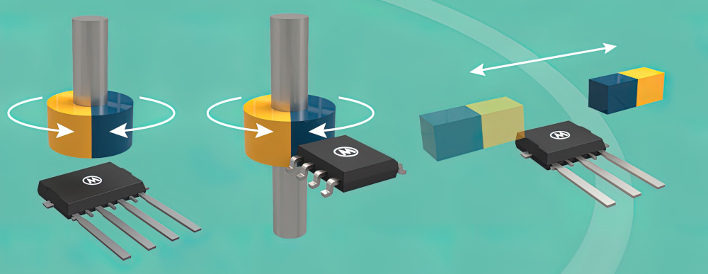
The sensors have traditionally been used for measuring the alternation, or repeated occurrence, of the magnetic poles within a rotor in a motor, with three sensors typically at a 120º angle to measure the speed and position of the rotor.
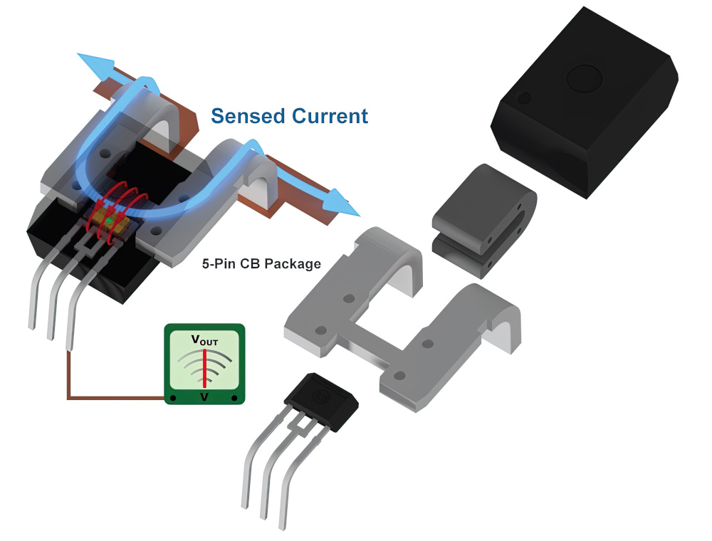
But the increasing sensitivity of the sensors, through the integration of more processing on the chip, new structures or new materials, is seeing more uses for them in EVs, particularly in measuring the current in and out of the battery pack. This is increasingly important for fast charging, where accurate measurement of the hundreds of amps flowing into the battery pack is essential to protecting the battery cells in the pack.
Hall sensors are also being used for load balancing of cells, providing more flexibility than existing shunt sensors. Shunts are essentially resistors in series, and so introduce losses. Coreless Hall effect sensors measure the magnetic field generated by the currents that are flowing and so are non-invasive and virtually lossless.
However, the sensors can be sensitive to variations in temperature, so maintaining the accuracy is a key challenge.
Other magnetic sensing technologies are also being adopted in EVs, from the giant magnetoresistance (GMR) effect to inductive sensors that use the tracks on a PCB as the sensor.
(Courtesy of Allegro Microsystems)
With a traditional Hall effect sensor, there are two conductor plates with a voltage between them exposed to a magnetic field. This field can be from a current or a magnet to measure the speed of rotation of a rotor. The key is that this is a well-established simple, reliable and robust technology, which is seen as a key requirement for automotive designs.
With EVs there is a focus on measuring the higher magnetic field strengths that come from higher currents. These can come from the voltage of battery packs increasing to 900 V and above, and from fast chargers boosting the current flow into the vehicle at higher voltage. Current monitoring is also vital in home chargers for safe operation.
These higher voltages and currents create more sources of noise and stray fields, requiring more signal processing. With Hall effect devices based on standard CMOS silicon chip technology, this processing can be added to the chip. This integrated processing also reduces the risk of external noise reducing the accuracy of the results. While the sensor itself is almost immune to the effects of electrical noise, taking the signal off-chip can increase the opportunity for noise to enter the system.
Some Hall effect sensors use materials such as gallium arsenide (GaAs) or indium phosphide (InP) that are more expensive to process, to achieve more sensitivity as there are more carriers – that is, electrons available – compared to silicon. However, more processing can be integrated into the silicon devices to compensate for that, and the resolution of the signal is determined more by the operational amplifier and analogue-to-digital converter (ADC) for the signal conditioning than the intrinsic performance of the Hall sensor itself.
While the sensor may be immune to noise, there are other factors that need to be considered and compensated for. The on-chip processing also includes temperature monitoring and compensation for vibration, in particular for EVs. It might also include redundant circuitry for safety-critical system designs.
In some instances a magnet can be integrated into the chip package to provide a constant field for calibration.
There are different ways to arrange the Hall effect plates, sometimes with a differential output to eliminate noise and the temperature cycling and vibration
The signal conditioning circuits can characterise the performance and bias the sensor, compensating for environmental conditions. This is essentially a sophisticated look-up table with the results of the bias current at different voltages and currents.
There are also different resolution and sensitivity requirements for different applications. For example, a Hall effect device used for a current sensor on a busbar with hundreds of amps flowing through it only needs a sensitivity of milliamps. This can require less signal conditioning to provide a suitable signal-to-noise ratio.
Other Hall sensors used for rotational measurements for sensing speed might need higher sensitivity, as the magnetic fields being measured are much lower. Applications such as measuring low speeds when parking can require higher sensitivity.
For the rotational sensors, a key consideration is communication with the digital controller. This can be a traditional two-pin, two-wire interface carrying an analogue signal to an ADC in the controller, although there is increasing demand for a one-wire connection. However, there are fewer controllers available with such an interface.
Material such as GaAs and InP can also be used for GMR sensors that have multiple layers of materials rather than Hall plates. These can have more sensitivity than the typical 1% of a Hall effect sensor.
Resolution is critical for controlling the charging current steps in fast charging. Here, milliamp resolution is more than enough, as 1% resolution would be accurate to 1 A for a 100 A fast charger.
Designers are also now looking at making the Hall effect work for cell balancing in the battery pack rather than using shunt current sensors. These do not yet meet the accuracy requirements of under a milliamp, as the currents flowing between cells can be around 10 A for lithium ion-cells, which is where GMR sensors are being evaluated. However, Hall sensors can be suitable for cell chemistries such as lithium iron phosphate, where the higher accuracy is not required.
Sometimes Hall effect sensors are used to monitor the input to the pack; sometimes they are placed in selected areas in the pack. This becomes a challenge though, as the wires have to come out of the battery pack, which can leave the pack susceptible to electromagnetic interference. This requires very careful placing of the sensors within the pack.
A range of devices is possible with different designs of Hall effect plates, with versions for rotary and linear use, and with analogue or pulse width modulation (PWM) output or with Single Edge Nibble Transmission (SENT) outputs.
The SENT protocol is defined by the SAE J2716 Rev 4 standard. Sensors can support various SENT data frame formats (H.2 and H.4) as well as error signal transmission on fast and slow channels.
Several programmable output signal clamping levels extend the error signalling capabilities to indicate various fault conditions, such as under/overvoltage, under/overflow of the signal path, and overcurrent. The signal processing includes magnetic field range, sensitivity, offset, and temperature coefficients, and are programmable in non-volatile memory.

A one-pin programming interface enables simultaneous programming of several sensors via the output pins with a customised output from a magnetic input signal, and provides 10-bit output resolution supporting a maximum bandwidth of 5 kHz.
Other devices support linear or rotary measurements that are immune to stray fields with either analogue, PWM or SENT outputs. For safety-critical ASIL B applications there are versions with dual dies to provide redundancy.
Graphene
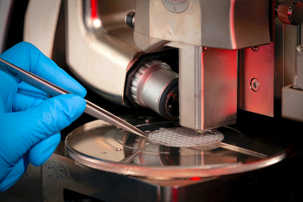
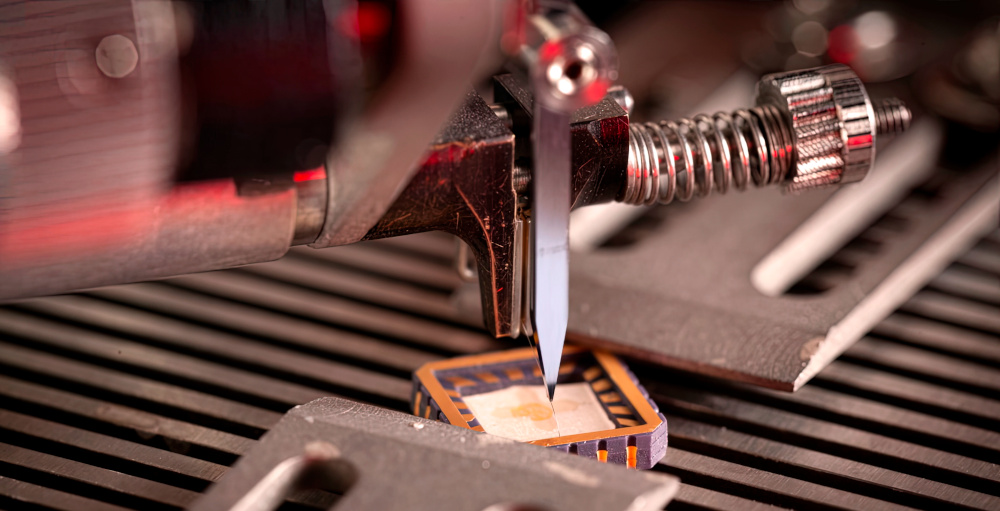
Graphene has emerged as a key material for Hall effect sensors. New process technology allows a layer of carbon one atom thick to be placed using a modified chemical vapour deposition (CVD) process that is very similar to that used for making silicon chips.
These devices have higher sensitivity than the silicon versions, but in the past were built by hand in research labs. Using a commercial process opens up volume production of the devices.
The sensor itself is a single plate of graphene with four terminals – two to provide the bias voltage and two to pick up the field induced by the magnetic field. These need a separate box for the signal conversion and processing, as different applications require different bias voltages. Eventually this electronics will be integrated into a companion ASIC device for particular applications.
The higher accuracy comes from the control over the number of carriers in the graphene, which can be tweaked by the CVD process.

The single layer of atoms avoids spurious signals in the sensor. Off-the-shelf silicon sensors have a depth that may only be a few microns, but that can create an error from movement. This error can show up as an offset on the output sine wave from the sensor.
The graphene Hall effect sensors have been tested with the high-power magnets at the CERN particle accelerator in Europe. Rotating the sensor through 360º showed that the graphene sensor could measure fields 100 times smaller than devices with silicon plates.
The size of the graphene sheet is also variable, allowing very small devices to be made. The active area can be from 10 to 100 µm2, and the size is determined more by the space for the contact pads. This opens up the opportunity to put thousands of sensors on a chip to create a magnetic field camera. The 2D nature of the graphene plate also avoids any crosstalk between the sensors in the array.
The smaller sensors are being used to pick up more of the current flowing through a cell, opening up a new area for characterising a pouch battery cell. Sensors can be placed on the top and bottom of the pouch cell to detect the size and direction of the different current flows in the various layers of the cell. This mechanism is not well-understood, but the measurements will help to characterise the cell performance, giving more information that can lead to improvements in the lifetime and safety of a cell’s construction.
Graphene Hall sensors are also being tested in fast charging systems with hundreds of amps to provide an instantaneous read-out of current alongside a PT100 temperature sensor, as the performance of the sensor is temperature-dependent.
Hall effect array
Hall effect sensors are also used in a massive array to create a magnetic field camera for inspecting equipment in the quality control of permanent magnet assemblies.
A chip, built in a silicon process, has a 128 x 128 array of sensors on a 0.1 mm pitch to give a matrix of 16,384 sensors on a chip measuring 12.7 x 12.7 mm. Reading the sensors in 800 ms provides an image of the magnetic field’s distribution Every sensor locally measures the magnetic field, and the distribution allows many properties of the magnets to be derived.
The camera array uses basic physics inherent in the field to calculate the overall magnetic field around the magnet. That means the field at a particular distance, for example 2 mm from a magnet, can provide the data for distances at 0.5 mm and 5 mm without having to move.
The algorithms in the camera’s control software are computationally correct and are based on the Maxwell equations to give the depth, or Z, data. These algorithms give the Z data for the entire field from a single point, given that the field can be measured as the boundary condition.
(Courtesy of Paragraf)
This is used to measure the field around high-performance individual magnets or those assembled in a complete motor.
Scanner systems can map a larger area using a robot. This moves the sensor in steps and stitches the data together to satisfy the boundary conditions for larger magnets.
The array is built using a standard CMOS silicon process that allows the signal processing electronics to be integrated. The Hall plates that act as pixels are cross-shaped flat resistors of n-type doped silicon with four terminals, and each pixel can be selected individually without cross-talk in a patented innovation. A current is sent in one direction through the cross, and the Hall voltage is read out across the other two terminals, producing an analogue signal that is proportional to the field at that location.
Each pixel sensor is surrounded by a number of selection and read-out transistors across four lines per row and four lines per column, and the data is read out by multiplexing the sensors. This produces an output analogue signal that is amplified and digitised.
The field that can be measured is typically around 1 Gauss, which is 0.1 mT, and is calibrated in a very stable environment using a calibration magnet in a temperature-stabilised chamber. This chamber can also be used by customers for recurring calibration. The fields detected are typically for magnets used in rotary encoders.
(Courtesy of Magcam)
This type of camera is moving from the research lab to the production environment, which requires a faster output. A number of measurements are averaged to get a better result with less noise, but for a faster measurement the number of sensors can be reduced, for example reading every other sensor to provide an output that is four times faster.
For rotor measurements, the array typically measures one line as the rotor is rotating, as it doesn’t make sense to measure the whole 2D array. The field is cylindrical, so there is one line that is key. This gives one measurement line at a particular angle that determines the entire field. Similarly, the number of pixels can be adjusted in each line, for example by using every other pixel for twice the speed.
Longer lines can be used to measure a rotor in fewer revolutions. A rotor might be 150 mm long, so to cover the whole surface with the 12.7 mm array would require multiple devices on a PCB to test a rotor in one revolution.
Motor makers are now looking to add this type of camera array to production lines for 100% inline quality control of the magnets in the motors.
The sensor array can generate an image of the full 2D surface, which can identify issues such as cogging torque in the rotor that cannot be detected in other ways.
Cogging torque, or no-current torque, is the torque resulting from the interaction between the permanent magnets of the rotor and the stator slots. This is position-dependent, and its periodicity per revolution depends on the number of magnetic poles and the number of teeth on the stator. This can be prominent at lower speeds, producing jerkiness, and using the array can identify the fluctuations in the magnetic field during assembly.
Rotary encoders
Rotary encoder magnets are a very important class of sensors used in automotive applications. The magnets are typically two-pole magnetised and work with a magnetic field sensor.
The quality of the magnet plays a crucial role in the accuracy of the finished encoder system, and the performance is typically measured at a few millimetres from the sensor with a 50 mT field, which is where the sensor algorithm is very practical. This allows a field of typically 200 mT to be measured at a distance of 0.5 mm to provide a noise-free image of the field at 50 mT.
This allows the camera to go down to the microTesla range and measure the angles of the field in the rotary encoder. If there is any lack of uniformity in the magnets then there will be ripples in the field at a particular angle, and that can be used to characterise the magnet and predict the angle deviations that will be seen in the encoder systems.
This is possible because the array measures the whole surface of the magnet and the strength and orientation of the field at each position. That gives the angle error that the encoder will see, so it can be predicted before the whole system is assembled.
This can compensate for inaccuracies in the magnet in the encoder, but there can also be a large variation in the quality of magnets, and with some magnets it may not be possible to apply that compensation. The variations might come from plastic-bonded magnets that have magnetic material mixed in the plastic and then moulded; any non-uniformity in the plastic can create variations in the magnetic field.
The array can also detect magnets that are not well-magnetised, for example those that have a double pole. Instead of a North-South pole there is a transition from North-South to North-South. This can happen if the magnetising yoke that creates the magnet is not well-positioned.
(Courtesy of Magcam)
Quality control of magnets is becoming more important, and the array sensor can be used to sort magnets into different versions, from premium ones for high-quality encoders requiring high levels of stability and accuracy to those suitable only for certain applications with compensation. This also helps to identify poorly performing magnets that cannot be used, and the sorting can be done by the magnet manufacturer or encoder developer.
The array sensing is also increasingly important for assessing the field in the axial motors used for in-wheel motors or electric aircraft, where higher magnetic fields are used. With an axial motor, the rotor is flat, which is well-suited to the flat-array sensor. A version of the array sensor has been developed with a laser sensor that measures the surface of the rotor and the magnet with the magnetic field to control the distance.
Alternatives
Developers of DC motor control systems are now looking at replacing the magnets needed for Hall effect sensors with inductive sensors that can be integrated onto simple, compact PCBs.
For example, an inductive sensor has been purpose-built for EV motor control applications with differential outputs, fast sample rates and features that make it ready for ISO 26262 functional-safety designs to the ASIL C classification.
PCB-based inductive position sensors use a primary coil to generate an AC magnetic field that couples with two secondary coils. A small metal target object disturbs the magnetic field so that each secondary coil receives a different voltage whose ratio is used to calculate absolute position.
By using the metal traces of the PCB rather than transformer-based magnetic windings and coil structures, the inductive sensor has negligible size and mass compared to alternatives that weigh as much as 450 g. The accuracy of these sensors is better than other Hall effect sensors, as they do not depend on the strength of the magnet, and the design of the traces can actively reject stray magnetic fields.
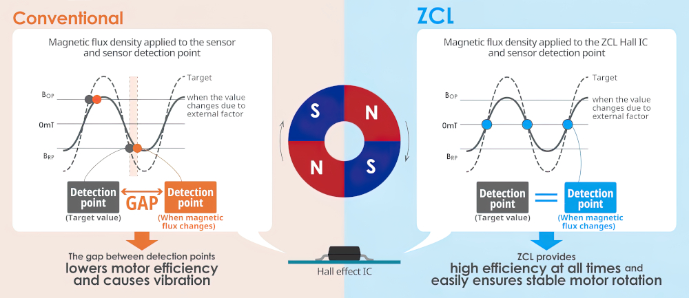
(Courtesy of ABLIC)
Zero Crossing Latch sensors
A Zero Crossing Latch (ZCL) Hall effect sensor uses a latch in the chip to change the output signal at the zero crossing point where the polarity changes. It can be used with brushless DC (BLDC) motors as it is not susceptible to changes in the magnetic flux density and temperature, and so provides stable detection. It also allows much greater flexibility in the positioning of the Hall effect sensor in the motor.
A conventional Hall effect IC detects the polarity and intensity of the applied magnetic flux density and switches the output signal. The ZCL Hall effect IC detects when the South pole of the applied magnetic flux density changes to a North pole or vice versa, and switches the output signal.
This prevents a reduction in efficiency owing to temperature changes and manufacturing variations, and simplifies the control software required for smooth, high-speed revolution.
The ambient temperature of a Hall effect ICs used as a position sensor in a BLDC motor changes significantly with the environment and load fluctuations. As the load increases, the coil generates heat that raises the temperature of the magnet, resulting in a change of the magnetic flux density that affects the IC.
In a conventional Hall effect sensor, the change in the magnetic flux density caused by the temperature rise in the magnet means the signal can miss the optimal timing for output, leading to a vicious circle of reduced motor efficiency and further rises in temperature. This is where a lot of work is done on the signal processing.
A ZCL Hall effect device senses when the polarity changes, and is capable of optimal timing output even if a magnet’s characteristics change as temperature rises. This prevents the successive reduction in efficiency that occurs when a Hall effect IC misses the optimal timing for output.
For various reasons, the distance between the rotor of the BLDC motor and a Hall effect IC is often not uniform. The machining accuracy of the rotor, the assembly accuracy of the rotation axis, bearings, rotor and other parts, the accuracy of mounting components on the sensor PCB and other factors during manufacture – in addition to vibrations during motor rotation – can also cause the distance between the magnet and sensor to vary.
For these reasons, mass-produced motors that had been expected to provide satisfactory efficiency at the design stage might exhibit individual variations in efficiency, also leading to variations in efficiency during operation.
A ZCL Hall effect device outputs a signal at the right time though, regardless of variations in the distance between the magnet and the sensor. Accurate rotational angle sensing is key to ensuring smooth, high-speed rotation in the motor. This requires integrating advance angle and delay angle control into the legacy motor control software, providing a temperature-based timing table, making calibrations to adjust for and absorb manufacturing variations.
However, if the factors that change magnetic flux density are used for detecting motor rotation, the software will need to perform more granular control to check a greater number of conditions.
Since a ZCL Hall effect device can detect a polarity change regardless of external causes, there is no need to perform calibration to account for changes in magnetic flux density. That means simpler software can be used to provide smooth rotation control without calibration.

Conclusion
Hall effect sensors are a standard component used in many parts of an EV, from steering encoders to wheel and motor speed sensors. New materials such as graphene are dramatically improving their sensitivity and opening up opportunities to characterise the performance of pouch cells and battery packs. Being able to measure the current in and out of the battery pack more accurately, instantaneously and non-invasively gives EV designers and fast-charger developers much more data about powertrain performance.
More integration of sensors for safety-critical designs and more effective signal processing are also driving the devices into EV platforms.
Greater integration, with thousands of Hall effect sensors on an array, is also helping to improve the assessment of magnets during production. This can help improve the quality of the rotary encoders and even axial motors, boosting the performance of EVs and electric aircraft.
Acknowledgements
The author would like to thank Motaz Khader at Allegro Microsystems, Koen Vervaeke at Magcam and Hugh Glass at Paragraf for their help with researching this article.
Some suppliers of Hall effect and magnetic sensors
Belgium
Melexis
Germany
TDK Micronas
Japan
ABLIC
UK
Paragraf
USA
Allegro Microsystems
Monolithic Power
Honeywell
Diodes Inc
API Technologies
–
+32 5722 6131
–
+49 761 517 0
–
+81 3 6758 6815
–
+44 1223 739782
–
+1 508 854 5800
+1 425 296 9956
+1 800 537 6945
+1 972 987 3900
+1 508 251 6479
ONLINE PARTNERS
