




Hairpin & advanced windings
(Image: Jingawire)
It’s not a wind-up
One of the most notable recent advancements in EV motor efficiency is linked to winding technology, as unravelled by Nick Flaherty
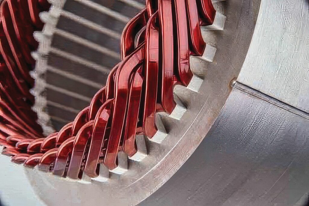
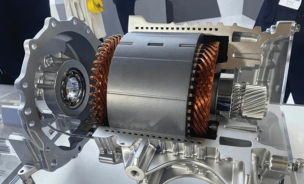
The shift from traditional round-wire windings to hairpin winding technology represents one of the most significant leaps in EV motor efficiency. By replacing bundles of copper wire with rigid, precision-engineered bars, manufacturers can pack more conductive material into the same space.
Hairpin windings offer numerous advantages over conventional random windings, and they are increasingly being adopted by automotive manufacturers. The rectangular cross-sectional geometry enables a higher slot fill factor, which improves stator slot utilisation and reduces the amount of insulation material required, thereby minimising losses. The robust design also supports higher current densities to increase the torque and power density, particularly during high-torque operations, without increasing the motor’s physical size.
From a thermal management perspective, hairpin windings provide significant advantages. The compact structure and uniform end winding configuration enhance heat dissipation and integrate seamlessly with advanced cooling methods such as spray and jet cooling (see below), significantly improving the motor’s thermal performance. Hollow hairpins can also carry dielectric cooling fluids to further improve thermal efficiency, but they present more challenges in manufacturing.
This trend underscores the potential for hairpin windings to become a dominant technology, from passenger vehicles to off-road and construction equipment.
Unlike traditional random-wound motors that use bundles of thin, circular copper wires, hairpin windings use more heavy-duty copper bars with a variety of cross-sections. These bars are preformed into a U shape resembling a hairpin before being inserted axially into the slots of the motor’s stator. Once positioned, the open ends of these pins are mechanically twisted and laser-welded together to create a continuous, high-performance electrical circuit.
(Image: University of Nottingham)
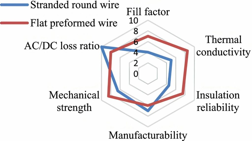
This provides a higher fill factor to improve the efficiency of the motor, as well as improved thermal management and simpler mass production.
Because the hairpins are rigid, the entire assembly process can be fully automated with high-speed robotics. This eliminates the variability of manual wire winding, ensuring the extreme consistency required for mass production of powertrains.
The improved copper slot fill factor reduces the space dedicated to slots and enables potentially higher torque and power density, along with a reduction in DC resistance. Assuming the same stator volume, a hairpin winding machine can be less saturated than its stranded winding counterpart, leading to lower iron losses. This is a key advantage, especially for drive cycles. EV motors usually have a small number of series turns, which means a large number of strands in hand might be necessary, causing significant AC loss. A proper hairpin winding combination of layers and parallel paths can significantly reduce this loss.
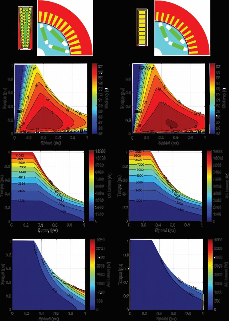
Owing to the lower DC resistance, the hairpin machine clearly has higher efficiency in the base point and a significantly larger high-efficiency region. This is also due to lower AC losses in the hairpin winding machine. Stranded winding requires bundles of parallel wires in the slot to meet the voltage requirement and reach a good copper slot fill factor. These bundles, which represent the effective series turns, are particularly prone to high AC losses due to the circulating currents in the parallel wires. The chosen hairpin winding design with eight layers has significantly less AC loss as a result of the lower slot height.
However, there are several variations of the hairpin, each balancing manufacturing complexity against electromagnetic performance.
The flat-wire hairpin winding for automotive applications was introduced in 1999 with a segmented winding embedded into the stator slot providing a direct heat path to the laminations. However, this also brought massive end winding welding joints, which required costly CNC bending equipment, a succession of stripping-, aligning-, twisting- and laser-welding steps for every segment, longer cycle times and higher likelihood of insulation damage.
(Image: Jaguar Land Rover)
Subsequent developments focused on trimming the segment count, simplifying welding operations and balancing multiple parallel paths to avoid circulating currents and losses.
Ambitious performance roadmaps for electric ground vehicles and aircraft powertrains are pushing traction motor designs to higher speed and fundamental operating frequency. To mitigate AC winding Joule losses, designers progressively reduced individual conductor dimensions by increasing both the stator slots and layer numbers. The direct side effect was an explosion in the quantity of welding points, increased end winding mass/volume and higher risk of insulation failure, leading to the development of different types of hairpin.
Types of hairpin
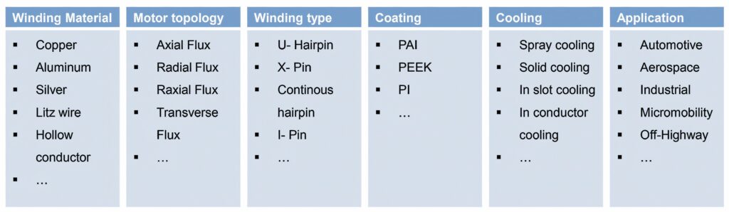
As well as the basic U-pin hairpin, the winding forms of flat wire motors mainly include the I-pin, X-pin and S-winding, or the continuous hairpin winding (CHW).
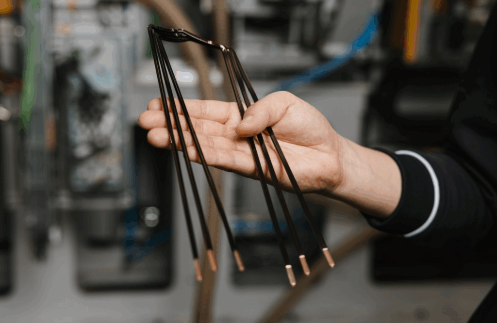
In the U-pin, the hairpin is first formed, then inserted and then welded on one side. It is the most widely used form of flat wire winding.
The process begins with enamelled copper wire being straightened, cut and bent into a U-shaped form. These pins are inserted axially into the stator slots, which have been pre-lined with insulation paper.
After insertion, the open ends of the U are twisted – a mechanical process where a nesting tool grabs the ends and rotates them to a specific pitch. The final and most critical step is the laser welding. Each pair of pins must be precisely aligned and welded to complete the circuit. This requires high-end 3D vision systems to guide the laser because even a micrometre-scale offset can cause a cold weld or excessive spatter, leading to motor failure. The high fill factor (of up to 75%) significantly reduces DC resistance, but the thick conductors suffer from the skin effect at high frequencies, where current migrates to the surface, increasing AC losses at high rpm.
I-pin
I-pins are simplified versions of the hairpin where the conductor is a straight bar rather than a pre-bent U and achieve a ‘slot fill’ of over 70%, significantly reducing resistance.
The I-pin winding is inserted directly and then soldered on both sides. There is no need for single-slot assembly, further reducing the space reserved for winding assembly. The disadvantages are that the welding process is cumbersome and the end size is large.
Unlike U-pins, which only require welding on one side of the stator, I-pins require welding on both sides. This doubles the number of welding points, which traditionally increases the risk of manufacturing defects. However, the technical advantage lies in the insertion process. Because there is no pre-bent crown, I-pins can be inserted into much tighter slots without risk of the crown catching or the insulation scraping. This allows for even more aggressive electromagnetic designs. To mitigate the double-welding drawback, a specialised bridge or busbar connector is included on one side to streamline the electrical interconnections.
The flat surfaces of the bars allow for better thermal contact with the stator core or direct oil cooling, preventing the motor from derating during high-speed driving. Because the parts are rigid, they can be inserted by high-speed robots, making them ideal for mass-market EVs.
However, there are drawbacks. At high frequencies, current tends to flow on the ‘skin’ of the conductor and because hairpins are thick, this creates massive losses and heat at high speeds.
Furthermore, once the tooling is set for a specific pin shape, changing the motor design can be expensive.
X-pin
The X-pin winding is an emerging tech where pins are crossed or braided to cancel out internal eddy currents. These designs are specifically engineered to reduce proximity effect losses, where the magnetic field of one pin reduces the current in the next.
However, this is expensive. Currently, the machinery required to bend and weave these complex shapes is far more expensive than that used on standard hairpin lines.
In a standard hairpin, the ends are twisted parallel to each other. In X-pin designs, the geometry is altered so that the ends cross over each other in an ‘X’ pattern before welding. This allows for a more robust mechanical joint and provides more surface area for a laser to create a consistent melt pool. Technically, this reduces the heat-affected zone during welding, protecting the nearby slot insulation from thermal degradation. It is often used in smaller, high-torque-density motors where space for welding tools is extremely limited.
(Image: Wafios)
Compared with a traditional hairpin, the X-pin has a lower end height, which can further reduce the size of the motor, which is conducive to the layout of the vehicle’s axial space and improves power density. Moreover, the manufacturing process is simpler than that for wave winding.
However, production line investment is based on the current hairpin production and investment in wire upgrading is relatively low.
The difference between the wire forming process and traditional hairpin forming is not significant, and it is important to focus on the forming accuracy because the X-pin does not have a cutting flat process, and the consistency of the pin angle after forming is high. Because the length of paint (insulation) removal is only about 5 mm, mechanical paint removal will cause the cross-section to not fully fit and the laser welding will leak. Therefore, only laser paint removal can be used.
So, the X-pin has higher precision requirements than the standard hairpin, and the equipment requires high wire feeding precision, which is difficult to implement.
Coating
A hairpin uses an impregnation paint + coating process to ensure insulation performance and strength.
The X-pin can also use the impregnation paint + coating process, but the welding area and pull-out force of the X-pin are lower than those of the hairpin, so it is recommended to use a higher-strength end potting process for insulation treatment. This process can improve the insulation performance and strength of the motor, and also improve its reliability.
X-pin motors have higher power density than hairpin motors, and the production process is relatively simple, which improves the efficiency of the motor.
At the same time, owing to the reduction of production processes, the complexity of X-pin motor manufacturing equipment has increased, and X-pin motor equipment requires higher precision control and stricter process requirements.
With demand for continuous development of new energy motor technology and the continuous optimisation of production lines, X-pin motors are seen as a key new trend for more efficient EV motors in the future.
X-pin motor automation equipment can provide semi-automatic and fully automatic winding and assembly according to customer process requirements.
Compared to a hairpin, the X-pin saves more than 20 mm of copper loss and can remove paint from both sides.
The biggest change point of the X-pin relative to the hairpin’s torsion head is the cancellation of the straight line segment, which makes it impossible to achieve the barrel twisting method. The lack of trimming technology means the end is not a flat surface. A new twisting process is needed to ensure the consistency of the cutting surface after twisting, and the control of twisting rebound requires extremely high equipment accuracy and algorithm compensation.
(Image: Honest Automation)
The X-pin is also soldered differently. Hairpins use hot melt welding where a solder ball is formed at the end. The heat-affected area is large, generally around 8–10 mm², the welding area is 110% of the cross-sectional area and the pull-out force is generally around 800–1000 N.
In contrast, the X-pin uses low-temperature welding. The solder ball is no longer formed at the end and needs to penetrate downward. The heat-affected area is required to be small, the welding area is 80% of the cross-sectional area and the pull-out force is generally about 600–800 N.
S-winding / D-pin
S-winding uses a continuous conductor that is preformed into a wave shape before being compressed into the stator slots.
Unlike standard hairpins that require hundreds of laser welds on the crown of the motor, the S-winding is continuous. This removes hundreds of potential failure points. The head of the motor (the part sticking out of the slots) is also much shorter, allowing for a more compact motor housing.
The implementation involves a winding mat that is preformed into a continuous wave and then inserted into the stator in a single motion or wound in radially. The primary technical benefit is the elimination of hundreds of weld points. Because the wire is continuous, the reliability of the stator is inherently higher, and the end turns – the copper sticking out of the slots – are significantly shorter, making the motor more compact. However, the machinery required to form a flat-wire wave without damaging the delicate enamel insulation is incredibly complex and less flexible for different motor sizes compared with that of standard hairpin lines.

However, managing a long, continuous wave of copper and forcing it into slots without damaging the insulation is a manufacturing challenge. The S-winding also cannot reach the absolute maximum density of individual I-pins because the copper needs a wider tolerance to be woven.
What sets continuous hairpin winding apart from traditional winding methods is its ability to reduce manufacturing complexity. The conventional hairpin design typically requires multiple assembly steps, including numerous welded joints, which can be prone to failure.
By eliminating most of these welding points, continuous hairpin technology not only improves reliability but also enhances design freedom. The drive for higher power densities, particularly in high-speed electric machines, is reshaping the manufacturing sector. Continuous hairpin winding is a key enabler in this evolution. It simplifies the complex winding process of traditional hairpins, offering a more streamlined and efficient approach, which is essential for high-speed, high-voltage applications. For OEMs, this holds significant promise. A more efficient motor requires fewer raw materials and has reduced weight, enabling OEMs to offer cost-effective products without compromising on performance.”
Continuous hairpin winding
CHW features a single rectangular conductor that is twisted continuously to create one entire phase branch. This eliminates most welding points per branch compared with conventional hairpin windings, lowers the risk of insulation degradation, improves cooling quality and reduces winding loss. This has been combined with a flat lamination bending technique, eliminating the need to fit windings into the cylindrical stator.
To further improve the compactness of end winding, a stepwise CHW has the terraced end turns shortened to reduce the DC winding resistance. The same geometry also eliminates inter-coil interference and promotes better coolant circulation. Guiding fixtures steer each sinusoidal conductor through the lamination stack while pre-interweaving multiple wires prior to insertion can provide more compact and mechanically robust assembly.
CHW features the same AC loss mechanisms found with its counterparts. At the conductor level, the AC loss is induced by the skin and proximity effect under the influence of the in-slot magnetic field. At bundle level, additional AC loss could be generated when different parallel branches feature asymmetric impedance. This is embodied as circulating current between branches, and can be effectively mitigated by using specific layout design rules.
CHW can be designed with higher slot numbers and winding layer numbers, but is more easily subject to additional circulating current-induced AC loss due to its more problematic design.
Another factor is that radial-insertion windings such as CHW require an open-slot stator. This increases slot-leakage reactance and typically elevates AC loss of conductors near the slot opening area. Magnetic or hybrid wedges can reduce the slot leakage flux, but they introduce extra cost and assembly steps. These open-slot penalties diminish as the slot number rises, making CHW particularly well suited to the high slot number, high frequency machines targeted for next-generation traction propulsion applications. Overall, CHW presents potential for further reducing AC loss compared with that of other flat winding options. However, given the limited amount of literature on this topic, there is no absolute conclusion that CHW is the most advantageous solution in AC loss mitigation.
The number of welds falls progressively from I-Pin and conventional hairpin, through diamond-lap variants, to its lowest in CHW. Each reduction shortens cycle time, lowers capital expenditure and removes the thermal–mechanical hotspots that can trigger partial discharge.
All flat-wire topologies already exceed stranded coils in dielectric endurance, but by eliminating every branch weld, CHW delivers the most uniform and reliable insulation system for high-voltage, inverter-fed motor drives. Welding can compromise insulation integrity, lengthen the process chain and enlarge the end winding envelope both radially and circumferentially. This restricts stator designs with many slots or radial layers.
To combat the efficiency losses at high speeds, thin hairpin designs are using multiple layers of thinner bars instead of thick ones. Breaking the conductor into thinner slices means the skin effect is minimised, allowing the motor to remain efficient at 16,000+ rpm. Additionally, more layers also mean more surface area for heat dissipation.
However, moving from four layers to 10 layers doubles the number of welds required, and a single weak weld can scrap the entire stator. Thinner pins also require more layers of enamel insulation, which can consume some of the space gains.
Under present manufacturing practice, welded hairpin solutions struggle to exceed 10 layers and 96 slots. In contrast, established CHW lines already support 16 layer conductors in stators with more than 120 slots. This scalability is key to reducing the size of flat conductors, curbing conductor level AC losses, and increasing the exposed surface for effective cooling to meet the higher frequency and higher power density requirements of next-generation traction machines.
However, there is a lack of comprehensive detail on CHW manufacturing techniques, as well as universally applicable design guidelines. In particular, there are extensive ongoing research elements in the winding layout theory of CHW, including critical areas of parallel branch and transposition designs.
The industry trend is currently leaning toward multi-layer thin hairpins. While they are harder to weld, they provide the best balance for modern EVs that need to cruise efficiently at highway speeds while maintaining the torque density needed for quick acceleration.
Hairpin winding technology has redefined EV motor design by replacing traditional ‘random-wound’ round wires with rigid, rectangular copper conductors. This transition isn’t just about shape – it’s a shift toward high-precision automated manufacturing.
Design tools
Manufacturing and assembly processes mean that the design of CHW is less flexible compared with that of a conventional hairpin. The selection of the parallel branches is limited by the wire numbers and the layer jumps of wires are fully determined by the winding pattern, while there is also layer asymmetry due to the radial shift. These constraints and features must be considered during the design stage.
Suitable manufacturing processes should be selected based on the winding parameters and the application. For example, choosing the appropriate winding direction based on the required number of parallel branches can save unnecessary welding. Deciding whether to adopt a non-radial-shift pattern based on the motor’s operating conditions and efficiency requirements can also optimise the motor’s performance and cost.
Reasonable and necessary slot transpositions should be used to achieve slot symmetry in parallel branches. Corresponding wires that exchange layer positions during the radial-shift region should be series-connected (if possible) to eliminate layer asymmetry. The ideal winding design should achieve strong symmetry to eliminate circulating current losses, but cost and manufacturing consistency should also be considered.
Irregular slot transpositions usually increase wire stress and the end height of the wire mat, causing manufacturing complexity and inconsistency. While achieving symmetry design, irregular slot transpositions should be minimised and, if necessary, placed in different slots to reduce the impact of the increased wire mat height on the rolling up and expansion process.
(Image: Ansys/Synopsys)
Design tools can automatically compute the hairpin winding wave pattern, dividing the scheme into different elementary windings. Each elementary winding is built to meet flux linkage balancing rules covering all the layers and all the slots per pole per phase, and represents a potential parallel path. Different parallel path combinations are possible by putting in series groups of elementary windings.
A design comparison for a traction application motor is shown above.
The two machines are designed for the same voltage, current and slot current density and have been optimised for the same output performance.
The hairpin winding motor enables a larger stator bore diameter with respect to the stranded winding solution, with the benefit of also having a shorter stack length and higher power density. The lower stator iron volume also represents an advantage in lowering iron losses.
Cooling
Efficient thermal management is critical for ensuring the performance and longevity of high-performance traction motors.
Traditionally, housing cooling jackets with indirect liquid cooling work by circulating a liquid coolant, typically water or a water–glycol mixture, through channels in the motor housing to absorb and dissipate heat generated during operation. However, with current trends towards high-density traction motors with hairpin windings, it is unrealistic to achieve the desired level of thermal extraction with only housing cooling jacket technology.
Oil jet impingement cooling can be used to meet the cooling capacity of several kilowatts per kilogramme of the machine.
A detailed geometric model of hairpin windings captures the fluid-winding interactions within a 45° sector of the motor end winding region, providing up to 10 times the thermal efficiency.
The well-defined gaps between conductor layers in the end winding region of hairpin windings create natural channels for coolant flow, which is a marked advantage over traditional random windings where tightly packed wire bundles limit coolant access to inner surfaces. By enabling cooling fluid to directly contact internal surfaces, these gaps facilitate superior heat extraction throughout the system. To maximise the thermal benefits of these natural channels, advanced cooling strategies focus on generating a continuous oil film layer across the stator end winding while optimising oil layer velocity, achieving enhanced cooling efficiency with minimal parasitic losses.
Spray cooling, in particular, has demonstrated good heat extraction capabilities. However, it typically requires higher pumping pressures – of the order of 7 bar – and more complex injector designs, which can increase system complexity and energy consumption. In contrast, oil jet impingement offers a more energy-efficient solution, achieving effective cooling with significantly lower pumping power requirements with inlet pressures as low as 1 bar. This significantly reduces the parasitic losses of the cooling system. Experiments with flow rates between 1–4 L/min measured heat transfer coefficients ranging from 100–250 to cool the winding.
A study on a motor from a Chevrolet Bolt EV studied the impact of different nozzle configurations and oil flow parameters on the cooling performance of the jet/spray. The findings indicated that dripping-type nozzles provided better cooling compared with that of full cone and fan spray nozzles, attributing this to improved oil film formation on the end windings.
Oil jet impingement cooling shows considerable promise for electric motor thermal management, despite current studies indicating lower overall cooling performance compared with spray cooling when applied to hairpin windings. Fundamental investigations into oil jet impingement on simplified geometries have demonstrated significant heat extraction potential, with studies showing that single oil jets can achieve local heat transfer coefficients as high as 8000 under optimal conditions. This suggests that a carefully designed array of impinging jets could potentially deliver superior thermal management for hairpin wound motors. However, the combined effects of nozzle orientation, mount configuration, diameter and distance from the winding surface, as well as jet velocity and flow rate, remain poorly understood for hairpin winding geometries.
Acknowledgements
With thanks to Martin Bauer at Wafios, Satyender Bidesi at JLR, Honest Automation and Hailin Huang of the University of Nottingham / Guangzhou Institute of Science and Technology.
4D Photonics
Accurex Measurement
Cascadia Motion
Denso
Honest Automation
Jingda Magnet Wire
Odawara Automation
Schaeffler
Synopsys
Technax
Wafios
ONLINE PARTNERS