


H3X
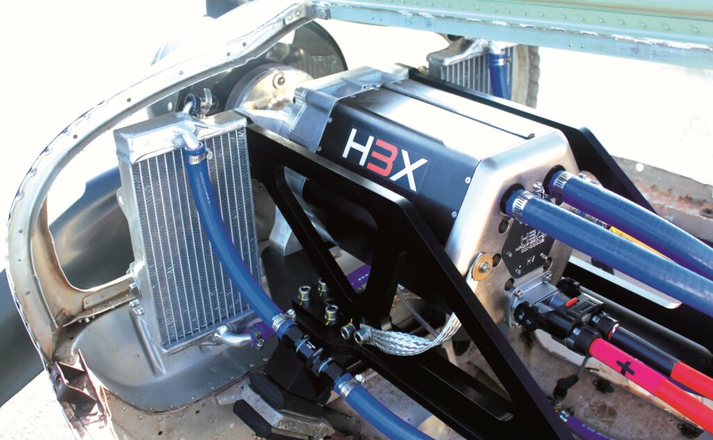
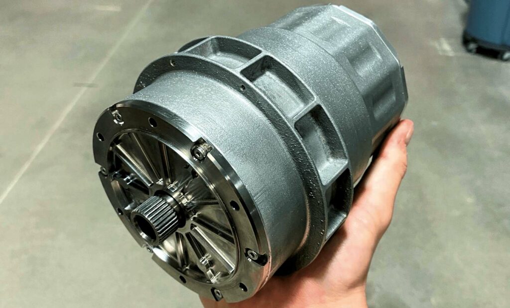
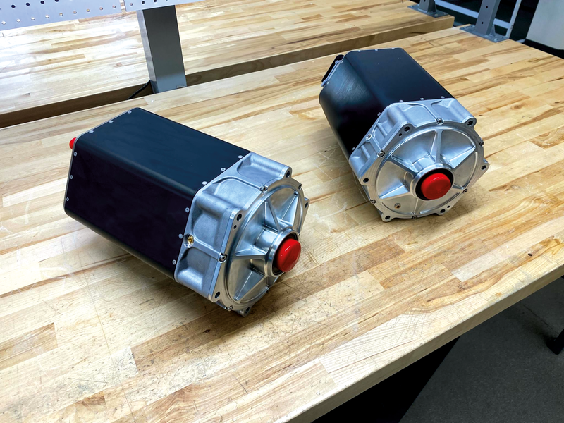
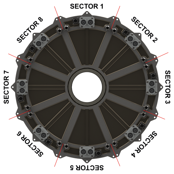
(Images courtesy of H3X)
Power of three
H3X is meeting the challenge of maximising continuous power output against high operating temperatures. Rory Jackson reports
Commercial aviation is one of the world’s fastest-growing sources of pollution, responsible for about 2% of global greenhouse gas (GHG) emissions and 2.5% of carbon emissions. These levels are projected to reach around 20% by 2050. As airlines emit CO2, NOx and contrails at high altitudes, their impact on global warming is more complex and probably more severe than simple metrics indicate.
Sustainability in aviation is therefore critical to keeping Earth habitable, and humans connected across oceans and continents. However, so-called sustainable aviation fuels (SAFs) remain many times more expensive than kerosenes, and producing them often depends on diverting land use away from food production or acquiring new farmland through deforestation, and burning them may still release NOx, contrails and other pollutants.
For many, e-mobility presents a more achievable means of sustainable flight, with a focus on lighter batteries to suit aircraft weight and enable zero-emission flight. However, as battery innovations can take decades to scale and certify, many chemistry ‘breakthroughs’ have failed over the last century.
Further downstream in electric vehicles (EVs), there is underused potential for reducing the weight of propulsion systems to make extra room for onboard energy storage, which could increase aircraft ranges considerably without needing new advances in batteries or fuel cells.
Today’s complete electric propulsion units (EPUs) – encompassing motor, inverter, gearbox and all related housings – typically have cumulative thermally-continuous power densities of about 3 kW/kg.
But the US’s Advanced Research Projects Agency-Energy (ARPA-E) has determined that a powertrain of at least 12 kW/kg and 93% power efficiency could enable all-electric flights for single-aisle, 150- to 200-passenger commercial aircraft, such as Boeing 737s, on today’s battery and hydrogen fuel-cell systems. As such aircraft output nearly half of all aviation-related GHG emissions and will generate the most global growth in future passenger miles, decarbonising them will have the greatest impact on energy and emissions of any aircraft model.
We have the technology
Although ARPA-E in late 2019 declared such targets to be “beyond the capability of state-of-the-art technologies”, Colorado-based H3X has developed and engineered a portfolio of integrated motor drives that target ARPA-E’s published criteria for electrified aviation – currently achieving about 9.5 kW/kg, with further improvements expected to reach 12 kW/kg within the next year.
Internal physics-based modelling by H3X has shown that, in some cases, the high-power density of its motors can more than double the range of electric narrow-body aircraft by freeing up considerable mass for adding batteries or fuel tanks. The company has created three product platforms to suit different power requirements, each consisting of a motor and inverter, and a gearbox where practical for torque output.
In order of size, these are: the HPDM-30, which weighs 4.1 kg and outputs
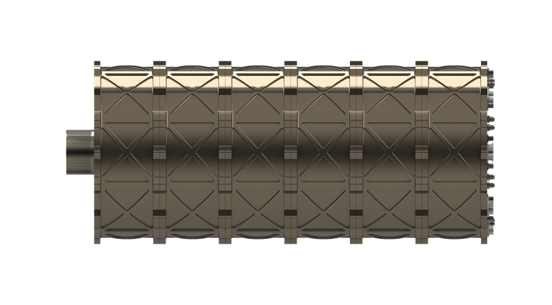
33 kW of continuous power; the HPDM-250, weighing 18.7 kg (H3X is working to reduce this to 16.6 kg) and producing up to 200 kW continuously; and the still-in-development HPDM-1500, which is anticipated to weigh 130 kg and generate 1.5 MW continuously. The HPDM-1500 can be stacked – up to six units on a common shaft – to build up to a 9 MW system, weighing 780 kg.
While these are the three motor platforms that H3X is currently focused on commercialising, the scalable core technologies it has developed can be used to create solutions optimised for aviation, marine, industrial and defense applications.
From small beginnings
H3X was founded by CEO Jason Sylvestre, chief technology officer Max Liben and president Eric Maciolek, who met at the University of Wisconsin-Madison (UW-Madison) via Formula SAE, where they were part of a university team designing, developing and manufacturing a small race car to compete in an annual sprint event against other universities around the world. In their second year, Liben and Sylvestre founded the electric race team at UW-Madison.
“We learned that not all commercially-available high-voltage [HV] powertrain subsystems are made equal – the inverters we had were scaled-up hobby ESCs with basically no protection circuitry, no active monitoring; they’d blow up left and right,” Liben recalls.
“So, in 2018, we decided to build our own motors, inverters and in-wheel planetary gearboxes, alongside the battery pack that every team had to make every year, and we did it from scratch in less than a year to qualify for the 2018 season. We got fourth-place overall plus first-place in a design competition.”
Post-graduation, Sylvestre successfully started his own power electronics consultancy and worked hands-on with silicon carbide (SiC) inverter designs. Maciolek worked on MW-class electric and hybrid powertrains, while Liben became a powertrain architecture and simulation engineer at Tesla.
Before long, the three friends heard about ARPA-E’s ASCEND programme, which aimed to encourage industry and academia to develop power-dense, integrated motor drives for electric aviation – containing the aforementioned powertrain requirements for electrifying commercial aircraft. Although H3X had not yet been formed, the three men felt confident in their skills and experience to develop a solution that would meet these requirements.
By late 2020, they incorporated H3X as a company and were accepted into the startup accelerator Y-Combinator, through which they gained significant learning resources and raised $4m to start developing their first prototype, which was completed in December 2021.
Now based in Denver, Colorado, H3X has since focused on proving out its core technologies and ramping up in-house manufacturing. Being highly vertically integrated has enabled a process of rapid development. Liben estimates that since December 2021, H3X has produced an average of one new prototype per month (26 to date) to test and validate new improvements for airworthiness and specific power.
System concept and architecture
All of H3X’s products are integrated motor drives, containing a permanent magnet synchronous electric motor, a SiC inverter and, in some cases, a planetary gearbox. These co-optimised systems are packaged together, sharing an additively manufactured structural housing with what H3X calls ‘synergistic cooling’.
“They are actively liquid-cooled, with the coolant channels formed inside the walls of the housing as it is printed. Having common mounting points and cooling channels for our motor and inverter saves a lot of complexity and mass in our design, compared with using COTS cooling plates,” Liben says.
Notably, the HPDM-30’s electromagnetic cross-section is identical in design to that of the HPDM-250 except for a shorter stack length, so their diameter is the same inside their housings. With their housings, they are 130 mm and 225 mm wide, respectively. The HPDM-250 is also wider due to its inverter being constructed radially around the motor (the HPDM-30 inverter is packaged axially behind the motor). Both motors are designed with 12 slots for the stator winding and 10 magnet poles in their rotors (12s10p).
Vital benefits of 12s10p
“A crucial benefit of the 12s10p approach is that the three phases of the stator are magnetically decoupled from each other. That gives us very sinusoidal line voltages and currents, and hence very fine motor control and low torque ripple, even under extremely high magnetic saturation,” Liben says.
“We also use a concentrated winding with very short end-turns – much shorter than the typical full-pitch winding. Combined with 12s10p, we get a winding factor [a measure of stator design effectiveness and an indicator of torque density, calculated as a function of the windings’ distribution factor, pole factor and skew factor] of over 93% with very low end-winding losses.”
The larger HPDM-1500 is a multisector machine with eight drive sectors, each equivalent in essence to one HPDM-250. To explain how the scaling works, H3X recommends first imagining the HPDM-250’s circular 2D cross-section and unrolling it into a line, creating a linear motor. If that line is copied and pasted eight times, a linear motor is created that is 8x longer. Finally, if one takes that line and rolls it back up into a much larger circle, the per-sector geometry remains approximately constant, so H3X can use the HPDM-250’s inverter and electromagnetic design for each drive sector in the HPDM-1500.
“Our winding method could also be used to make a more common 12s8p e-machine, but that would have performed weaker in every respect except vibration and acoustic noise,” Liben says.
“We’ve engineered our motor housings to suppress noise as far as we can. To a certain extent, a 12s10p e-motor will always be noisier than a 12s8p one, but when you’re driving a propeller or generating power from an engine, you typically can’t actually hear the e-motor over the prop or engine. We’ve observed that multiple times during our iron bird and integrated vehicle testing, and there will generally be noise isolators on the vehicle side to further keep conducted acoustic noise from propagating to passengers,” he notes.
In the HPDM-1500, each of the eight drive sectors is isolated thermally, mechanically, electrically and magnetically from the others, meaning any faults will rarely propagate between them, and a faulty section can be shut down without significantly affecting operations. Such failover mitigation would not be possible with a 12s8p baseline motor winding (or with any traditional distributed or full-pitch winding) due to the presence of magnetic coupling between phases.
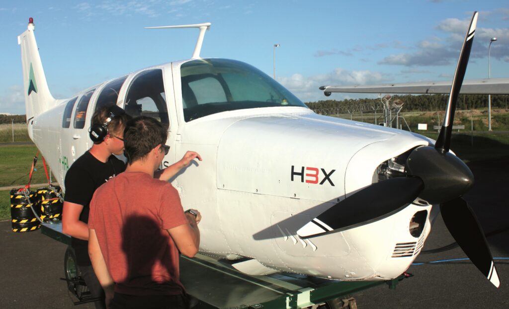
confirmed that the e-motors cannot typically be heard over the sound of the propeller
Building bigger
“The 1.5 MW HPDM-1500 serves as a building block for future 3 MW to
9 MW powertrains by stacking multiple -1500s along a common rotor shaft,” Sylvestre says. “The impact we can have from a decarbonisation perspective is directly linked to how much power we can install per application, so we very much want to develop larger and larger systems for marine, industrial and defence markets, with the long-term focus being the hybrid and fully electric aircraft market as it grows.”
The HPDM-1500 and larger multi-sector motors do not use a gearbox, because shaft speed drops inversely, proportional to the number of sectors. Thus, while the HPDM-250 has a shaft speed of 20,000 rpm, the HPDM-1500 has 2500 rpm. This is because the rotor-tip speed is maintained across platforms, so as the rotor diameter increases, rpm decreases. The torque increases with the square of the number of sectors; hence the gearbox becomes unnecessary for the biggest motors, enabling direct drive of the propellers.
“Using similar pole and winding designs across all our motors, [plus] similar inverter topologies, similar thermal management – it’s all key to how we’ve created this modular and scalable core technology platform, which forms the building blocks of increasingly large, but no less power-dense electric powertrains,” Liben says.
Stator winding insulation
Of the various subsystem-level innovations that are common among the motors, the first one that H3X chose to discuss with us was its HV stator winding insulation – a critical solution to the challenge of maximising continuous power output against high operating temperatures, which the company believes is arguably the biggest bottleneck in electric powertrain performance.
H3X’s solution, which it invented, is a proprietary composite material, combining multiple existing ceramic- and polymer-based insulating materials – the exact formula is closely guarded.
Traditional e-motor manufacturers often sidestep the thermal bottleneck by running an active and direct cooling medium in contact with the stator windings. This involves either flooding the stator with oil or designing in-slot cooling channels that enable water-glycol to run immediately adjacent to the conductors. Each strategy mandates dedicating copious space in the stator to components that are not conducting current.
“Just pumping coolant at higher flow rates won’t solve it, because the temperature rise from the coolant to the winding hotspot, due to the HV insulation, is a much larger fraction of the total temperature rise than anything attributable to the convective heat transfer between the cooling liquid and the housing,” Liben says.
“We’re talking maybe a 10 C rise from the liquid to the housing, whereas you can develop hundreds of degrees celsius temperature difference due to the winding insulation.”
This is why H3X developed the most thermally conductive stator winding it could, minimising the thermal bottleneck and creating more room in the stator for the copper conductor. The result is a bulk-winding thermal conductivity of 8.7 W/m-K and a thermally continuous current density of 47 A/mm2, with additional improvements in the pipeline. For reference, H3X comparatively baselines current state-of-the-art high-performance motors at 1.5 W/m-K and 25 A/mm2.
Thermally conductive
“Ceramics are exceptionally thermally conductive for non-metallic materials, while still being very electrically insulative. They don’t quite have the electrical insulation performance of polymers, but they do take the edge in thermal conductivity,” Liben says. “We’ve incorporated several different classes of ceramics and polymers into our insulation system in many different form factors. Although we’ve not used anything radical, it’s still a very different insulation approach to anything else we’ve seen out there.”
In addition, the stator is fully encapsulated to prevent partial discharge. This refers to the occurrence of minor arcing across small voids in winding insulation, which contributes to winding degradation over time. This was an important quality tracked by H3X while developing its insulation as it is a safety critical consideration for flight.
Overall, the high thermal conductivity of H3X’s insulation means that heat from the windings can be dissipated effectively with a liquid cooling jacket at the housing level, without any coolant entering the stator. In addition to their high thermal conductivity, the windings in H3X’s motors can operate safely and continuously at up to 265 C.
“That high-temperature performance comes mainly from the careful selection of the polymers, since all polymers’ molecular chains break down and start to carbonise once certain critical temperatures are reached,” Liben explains.
“It’s always going to be the polymers that limit your temperature capability, so we haven’t used any traditional polymers or encapsulants. We’ve looked across various industries, from automotive to aerospace, including outer space, in applications not related to e-motor thermal management. But, again, we’re not using anything crazy – our processes are fully scalable and our supply chains can scale with us.”

Endurance testing
The winding insulation has been tested in H3X’s vacuum chamber to simulate performance at varying air densities and altitudes, including running the windings to their maximum continuous operating temperature and performing surge testing to generate a voltage wavefront of up to 2600 V. H3X reports seeing no partial discharge from the windings to date at any altitude, across all temperatures and voltages, in the normal operating range of the winding.
“We’re still in the process of doing thermal endurance testing, cycling and ageing the insulation as much as we can to have a complete picture of how it behaves under every conceivable circumstance over time, but we have already accumulated a good idea of its properties versus conventional materials,” Liben notes.
“Our proprietary manufacturing process is also designed to get us to a very high slot-fill factor – about 70% if you count just the copper conductors – whereas state-of-the-art is around 50%, which contributes hugely to our superior current density. There is no dead space in the cross-section of our windings or stator slots. It’s all either copper or insulation, installed at a very deliberate thickness for partial discharge performance.”
Choosing stator laminations
The development and production of any stator begins with lamination choices. H3X opts for 0.1 mm cobalt iron laminations in its stators, but it has found that buying fully manufactured cobalt iron stacks from several suppliers generally results in some issues.
“One critical metric for a stator lamination stack is how accurately it can be made to very tight tolerance specifications; lamination misalignments consume precious space for windings and create a more troublesome surface for heat to travel through. The tight tolerances are also very important for maintaining a small air gap between the stator and rotor,” Liben says.
“Mechanical stacking factor is another key metric – how much of your stack is metal versus how much is adhesive? In some stacks we have over 1000 laminations and the adhesive doesn’t contribute anything other than holding your stack together. That’s important for assembling the stator winding, but it is not performance-critical in the end-application.”
These metrics would vary between H3X’s previous suppliers, with stacking factors ranging from 87% to 96%, which the company deems insufficient. Higher stacking factors often come with worse tolerancing of metal sheets. In rare instances, a stator would arrive with an excellent stacking factor and tolerancing, but ultimately weak bonds.
“To stick our 100 micron-thick laminations together with a high stacking factor, we needed an adhesive that could set at a one- or two-micron thickness between each lamination, but still provide strong adhesion at high temperatures,” Liben says.
“In fact, typical high-temperature lamination-bonding adhesives usually can’t hold up beyond 200 C, maybe 220 C, and we’re aiming to run our stator windings with 265 C hotspots. It’s even worse for the rotor and its magnet bonding, but in any case, we developed a specific and proprietary formulation of materials accessible by straightforward supply chains that would maintain adhesion at much higher than usual temperatures, as with our winding insulations.”
Simultaneously, H3X developed its own fixtures for stacking the individual laminations supplied externally with tighter tolerances than those of most suppliers. Combined with its in-house adhesive, H3X claims a 98% stacking factor, as well as continuous performance at 300 C without any adhesion degradation.

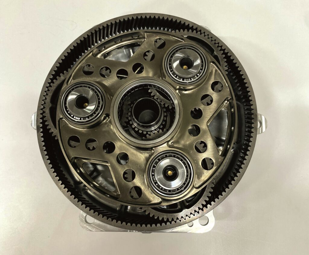
test versions of the -1500 ready to ship to customers by the end of 2024
Rotor performance
For its rotors, H3X receives 0.1 mm laminated iron sheets (either cobalt or silicon iron, depending on the application), as well as laminated and segmented permanent magnets at its facility. It then stacks the sheets, installs the shaft through the middle of the stack and inserts the magnets into the assembly, all using its proprietary adhesive for bonding. Lastly, some outer-diameter grinding and balancing is performed by third parties, although H3X plans to bring these processes in-house.
“We spin-test our rotors to verify their performance at room temperature and in a temperature chamber at 300 C,” Liben says. “Our rotor is not actively cooled; it has to reject its heat into either the stator through the air gap or out through the bearings. That means the rotor can get even hotter than 265 C, sometimes up to 300 C, given that it runs inside the stator, farther away from the housing and its cooling jackets.”
While the magnets and laminations tolerate 300 C without issue, the polymer adhesive imposes a temperature limitation. Structurally, the rotor primarily depends on the metal lamination geometry, and secondarily on the adhesive, to not burst apart. Traditional aerospace e-machines wrap a carbon-fibre sleeve around the rotor to compress the rotor components together, which is particularly useful for surface permanent magnet (SPM) architectures.
“So, again, the polymer adhesive is key to the rotor’s performance at thermal limits. It doesn’t play a huge role structurally in the final component since, mechanically, the laminations themselves provide far greater structural strength, but breakdown of the adhesive due to aggressive operating temperatures would still be unacceptable,” Liben notes.
Magnetic attraction
To create a motor that can operate efficiently even while extremely hot (without needing direct rotor cooling), samarium cobalt magnets were deemed the best choice.
“Past about 180 C, samarium cobalt gives you more air-gap flux density than neodymium. It’s expensive, but because of our high stator current, our power or torque relative to magnet mass [or magnet utilisation] is very good, so we don’t need a large quantity of magnetic material to produce 12 kW/kg of specific power,” Liben explains.
Additionally, the interior permanent magnet (IPM) structure achieves a higher air-gap flux density than SPM rotors with a sleeve. A typical sleeve acts similarly to air, creating distance between the stator and rotor, reducing the flux density, which can cross the air gap to create electromotive force and torque.
“We didn’t go the IPM route strictly for power density,” says Liben. “We determined that using an SPM rotor with a sleeve and spinning the rotor much faster would net even more power output, which could suit future turbogenerator or turbocharger applications, but that’s not optimal for primary propulsion or primary power generation at the MW scale.”
The IPM arrangement has been chosen to sacrifice significant speed capability in order to gain torque. If an e-motor must drive a propeller, the propeller’s blade-tip speeds will rapidly lose efficiency if forced to run close to the speed of sound, and the rotors will similarly lose efficiency if run too quickly.
A gearbox can help to get around these limitations (one is integrated into the HPDM-250). H3X has determined that to maximise power density in e-powertrains running at tens or even a couple of hundred kilowatts, it makes sense to run the e-motor at high speed and use a gearbox to convert speed into torque. Meanwhile, the MW-class powertrains can be run with slow enough shaft speeds and high enough output torque for direct drive operation.
“The necessity of a gear reduction at lower power stems from maintaining a reasonable aspect ratio of the e-machine to minimise the impact of end leakage on the air-gap flux density, while avoiding modal issues that can stem from very large or very small rotor L/D aspect ratios,” explains Liben.
He estimates that 320 kW is the approximate cut-off point above which a gearbox starts to become unnecessary and prohibitively large for increasing output torque relative to speed. The mechanical simplicity of direct drive is also seen as a significant benefit, especially for high-reliability MW-class applications.
Housing matters
The HPDM-250 is built with an enclosure consisting of an inner and outer section (whereas in the HPDM-30, the inner section forms the entirety of the housing).
The inner section is an approximately cylindrical part, additively printed from aluminium alloy for low weight and high heat transference. It features a circular bore for housing the stator and rotor, as well as a plethora of liquid coolant channels. In the HPDM-250, a series of flat surfaces are arranged radially around the outermost part of the inner housing, upon which the inverter power electronics are mounted. In the HPDM-30, the inverter-power electronics are arranged axially off the back of the inner section.
“In the -30, the inverter gets enclosed within the printed housing, but in the -250 a second, outer housing is necessary to protect the inverter boards, as they sit around the outside of the cooling channels and the structural inner housing, so the outer housing is constructed from bent sheet metal and then sealed, and it functions as both EMI [electromagnetic interference] containment and general environmental protection for the electronics inside,” says Liben.
“We use direct metal laser sintering [DMLS] for the inner housing structure. Additive manufacturing has come a long way in the last few years, such that we can print multiple parts per printer simultaneously, and it isn’t overly cost or time prohibitive anymore, but we are evaluating a switch to casting the inner section when we get to large enough volumes.”
While other additive manufacturing techniques were available, DMLS was deemed the most technologically mature, particularly for aluminium alloys, and the batch production of components was enabled by the larger format of these printers.
Coolant designs
For thermal management, water-glycol liquid coolant typically flows through channels that run helically in several turns inside the radius of the inner housing between the stator and the power-converter modules. Cold liquid enters one side of the powertrain, increases in temperature as it collects heat from the stator and inverter, and then leads through a port on the opposite side.
In the HPDM-250, the coolant then flows through the gearbox housing, where it extracts heat from the gearbox oil. For a hybrid application, fuel could also be pumped through the channels to be used as coolant before being burned in an engine, which removes the requirement for (and mass of) a dedicated coolant pump and radiator.
“The coolant-channel design is actually deceivingly complex, since you need to balance the convective heat transfer coefficient with the pressure drop, and also with the housing stiffness – that last one is particularly important because our power electronics are closely connected to the electric motor and its vibrations, so the geometry of the cooling channel influences the behaviour of the motor under high-vibratory conditions,” Liben notes.
“We could have gone with a system of several parallel axial channels from front to back with manifolds at either end, and that might have increased our total volumetric flow rate and reduced the required pumping power, thanks to the less restricted path taken by the coolant. But it would have decreased the flow velocity per channel quite significantly, and so the coolant wouldn’t be turbulent enough for a good convective heat-transfer coefficient,” he points out.
Lastly, the housing holds the rotor shaft in high-temperature bearings. These are hybrid bearings with metal raceways and ceramic rolling elements, which are used for their long lifespan, high speed tolerance and low temperature rise. Additionally, while some e-motors can suffer arcing through their metal ball bearings between the inner and outer bearing races (due to the build-up of common mode voltages on the rotor, which are drawn towards the chassis ground), this is prevented by H3X’s use of ceramic rolling elements, combined with the design of a grounded connection to the rotating shaft.
Inverter challenges
H3X’s inverters use SiC devices and have a power-conversion efficiency exceeding 99%. SiC MOSFETs are an increasingly common sight across e-mobility for their fast switching speeds, high power density and high efficiency, but using SiC in aerospace poses a bigger challenge than in road and marine applications due to the higher EMI and reliability requirements specified by aviation authorities.
While many regulations are published by the FAA and EASA, aerospace EMI limits are set by the standard DO-160, published by the Radio Technical Commission for Aeronautics in the US.
“DO-160 was made many years ago for lower-voltage electronics, not high-voltage power systems, and its interference requirements stemmed from aircraft communicating over sensitive AM radios. Because of SiC’s high switching speeds, it’s very hard to get EMI levels down to a value that passes DO-160,” says Sylvestre.
Integrating the inverter with the motor has been key to H3X realising SiC’s full potential while achieving compliant EMI performance. Mounting the inverter as a separate but still regulation-compliant device would have mandated heavy and loss-prone filters on the system’s input and output, Sylvestre explains.
One reason for this is that the separated motors and inverters are often connected using long, shielded phase cables.
“Those cables end up working like a transmission line; they can induce substantial ringing [oscillation] in the motor winding, leading to insulation degradation and additional EMI. They also provide increased surface area for noise currents to potentially escape. The phase cables can carry a very high common-mode voltage, and when combined with the capacitance of the shielding, this can result in more difficulty preventing common-mode current from egressing on to other circuits within and beyond the powertrain,” Sylvestre says.
Integrating the motor with the inverter reduces the phase-connection distance to a few centimetres, while minimising the engineer’s EMI filtering and containment burden. It also enables lightweight EMI filters to be integrated in a very tight manner between the motor and the inverter. As a result, so far, H3X’s dyno, iron bird and integrated vehicle tests have not turned up any EMI-related functional issues.
“That might not sound like a big deal, but it’s really challenging to get SiC inverters to not wreak havoc on neighbouring systems,” Liben explains. “Some of our customers have tested other SiC inverters in their platforms with disastrous results and sometimes weeks of troubleshooting to even get a working powertrain out of them.”
Mitigating SiC EMI issues
Also important is the management of sources of parasitic impedance across the e-powertrain.
“For instance, the DC link capacitor and busbar inductance directly influence the switching overshoots and ringing in your SiC devices, which in turn lead to EMI, so we’ve designed a very low-inductance bus structure, allowing us to operate with very low overshoot and ringing,” Sylvestre says.
“That overshoot reduction allows us to push our bus voltage up to 900 V while still using 1200 V switching devices. As another example, parasitic capacitance between the switch node and the grounded low-voltage [GLV] system has to be managed, so we install tightly coupled filters – which is possible thanks to our integrated approach – to create a very low-inductance pathway for common-mode current to travel back to its source. That helps prevent situations where common-mode currents egress into the GLV and control circuitry.”
The most common strategy for mitigating SiC EMI issues is to intentionally reduce switching speeds by increasing gate resistance. This scales back MOSFET-level problems such as overshoot and ringing, but it eats away at the efficiency and power-density benefits of using SiC in the first place. H3X claims it can often run its systems with zero external gate resistance, meaning the transistors switch as fast as physics allow. H3X also claims it has observed dv/dt (the rate at which voltage changes over time) and di/dt (the rate at which current changes over time) as high as 40 V/ns and 35 A/ns, respectively, during double-pulse testing.
“Our grounding and shielding strategies are very meticulous and intentional in our inverter, as is our PCB layout, which is designed in-house, including our own gate-driver circuitry,” says Sylvestre.
“A lot goes into our gate-driver design to minimise inductance and interference between circuits, and to define return paths. EMI issues in a circuit often stem from poor return-path routing. We’ve also got galvanic isolation between the LV controller and the higher-voltage gate drivers and other HV parts, and so a lot goes into ensuring proper clearances, creepage distances and HV insulation, including minimising stray capacitance at the interfaces between the HV and control circuitry.
“Of course, developing a secure supply chain is critical for developing SiC inverters. We’ve got an excellent working partnership with Wolfspeed, which is one of our SiC suppliers and probably one of the biggest out there, and we work very closely with them on product development, production planning and road-mapping future core-technology improvements. Lead times for SiC are still long, and there are constant high-volume orders for Wolfspeed’s product, so we work closely with them to ensure we have the inventory we need when we need it,” Sylvestre adds.
Configuring the gearbox
The gearbox is a single-stage, single-speed device, and this mechanical simplicity is ideal for aerospace as it minimises maintenance. It is an epicyclic gear system (arguably better known as a planetary gearset), which H3X has designed in-house to optimise its power and torque densities.
“It’s set to come in two standard configurations: one we’ve already alluded to, and that has a trapped volume of oil in it, which gets churned and splashed by the planetary gears in order to lubricate everything and cool the gearbox components,” Liben says.
The other option that H3X is developing consists of a gearbox configuration designed to function with an external oil pump and filter. While this will make for a more complex and heavy arrangement, the company anticipates it may make maintenance easier; for instance, by enabling longer intervals between oil changes.
“While our lower-power products require this gearing in many applications, we anticipate that the majority of applications for our future products above 320 kW will be capable of directly driving the load, with all the benefits of reduced maintenance that follow from that,” Liben adds.

Motor control
In the HPDM-30 and -250, a dual-core microcontroller unit (MCU), optimised for motor-control applications, is built into the inverter, and multiple such controllers can be run simultaneously on a common bus. The integrated motor drive requires a command setpoint to be sent to the unit, and the user can request torques, speeds or bus voltages, depending on which of the three corresponding modes is set to ‘active’ (the former two request modes apply best to propulsion configurations, while the third is meant for power-generation applications).
Considerable internal information on the powertrain is tracked via sensors, which can be provided to the vehicle’s comms bus, and hence to the operator or technicians. These include heat measurements at every crucial location where hotspots can form (such as the motor windings, SiC power modules and bearings), including a non-contact, infrared-based sensor for gauging the rotor shaft’s temperature in the HPDM-250.
In future, H3X plans to implement more data-focused features, such as accelerometers to estimate the remaining lifespan of bearings based on acceleration and vibration profiles, and a means of detecting non-catastrophic winding faults via current measurements. While temperature measurements can pick up both things indirectly, H3X feels it prudent to develop additional approaches to maximise robustness via diverse sensing methods, and to one day enable more powerful predictive maintenance indicators.
The torque request mode is the most straightforward: the inverter regulates the phase current supplied to the motor to achieve the user’s desired torque output. Speed control is implemented via an outer control-loop around the torque-control subroutine. Upon receipt of a speed request while the user has set the powertrain to speed-control mode, the outer loop regulates and changes the torque request to maintain the corresponding rpm speed.
In the power-generation mode for hybridised powertrains, the controller can regulate the inverter’s HV DC bus to maintain a setpoint voltage by regulating the motor shaft torque, and hence the DC bus current. That charges or discharges the bus capacitance, depending on the load current on the DC bus.
“This is a little unique to us – particularly as we offer it as part of our controller, rather than as another separate box of electronics. It can be really useful for applications where subsystems like avionics, HVAC systems or hydraulic pumps are also powered off the HV bus, and so the system integrators want to stiffen the bus voltage in the absence of something heavy, like a battery, to regulate it,” Liben explains. “Even if a battery is present to passively regulate the voltage, this algorithm can still help the battery to maintain a particular state of charge amid varying loading conditions.”
Testing a trio of controls
Determining the necessary parameters to develop speed, torque and voltage control modes began with the generation of high-fidelity flux and inductance maps through electromagnetic simulations. A software-in-the-loop (SIL) model was created, pairing a real-time virtual model of the motor with the actual motor-control firmware for controller architecture development and tuning various gains.
Once the SIL model’s performance was adequate, dynamometer testing of real hardware was performed, during which the control response was verified and necessary adjustments were determined for accuracy across the three modes.
Field-oriented control (FOC) is the method of choice for smooth motor operation and high dynamic performance, with phase-current regulation performed via space-vector modulation.
“The algorithms and firmware are written in-house, as is a self-sensing [‘sensorless’] rotor-position estimation algorithm, used in the HPDM-30,” says Sylvestre. “The -250 uses a resolver, but in the -30 we didn’t physically have enough space for one, so we developed this algorithm.”
“For the MW-class powertrains, we’ll use a combination of both, as that will provide a redundancy in determining the rotor position. The self-sensing routine also runs in the background on the HPDM-250 to sanity check the physical resolver’s outputs and function as a fallback in case of a resolver fault,” he adds.
While there is only a single controller in the HPDM-30 and -250, a more distributed control architecture has been designed for the -1500, -3000 and other multi-sector, MW-level machines.
“The -1500 uses eight independent controllers,” says Sylvestre. “We use a control algorithm, similar to how generators on the electrical grid evenly share load, so that all drive sectors are producing equal torque on the rotor without any controller-to-controller communication, even while they are all in speed-control mode. That’s important from a FMEA [failure mode effects analysis] perspective, because if there’s a fault in one controller, there’s no pathway for the fault to propagate to another.”
Future ambitions
Having tested and validated its prototypes and their designs, H3X next plans to expand production of the HPDM-30 and -250, while continuing their reliability and environmental testing throughout 2024, as well as the development of its MW-class EPUs.
“The high level of shared technology between the kW-class and MW-class machines means the latter are fairly de-risked already, but there will certainly be new challenges to solve when we start prototyping them. We’re aiming to have test articles ready to ship to customers for ground testing by the end of 2024,” Sylvestre says.
H3X aimed to improve power density by 3x (hence its name) prior to investing millions of dollars in the certification of its products. This ensures that by the time its certified systems become commercially available, they will feature the necessary power density to enable meaningful inclusion in narrow-body aircraft and improve their environmental impact.
Importantly, H3X plans for the -1500 to be the first motor it puts through certification with the FAA. Since the product is slated as a core building block for commercial aviation, certifying it first is expected to help considerably in enabling H3X’s future roadmap, including certification and scale production of 9 MW (and larger) electric aircraft powertrains.
Key specifications
HPDM-30
Permanent magnet
synchronous AC motor
12s10p
Inrunner
IPM rotor
SiC inverter
Mass: 4.1 kg
Volume: 2.07 L
Length: 156 mm
Diameter: 130 mm
Peak torque: 19.6 Nm
Peak power: 41 kW
Top speed: 20,000 rpm
Maximum continuous torque: 15.8 Nm
Maximum continuous power: 33 kW
HPDM-250
Permanent magnet
synchronous AC motor
12s10p
Inrunner
IPM rotor
SiC inverter
Mass: 18.7 kg
Volume: 8.77 L
Length: 282 mm
Diameter: 225 mm
Peak torque: 800 Nm
Peak power: 250 kW
Top speed (at output shaft): 2975 rpm
Maximum continuous torque: 640 Nm
Maximum continuous power: 200 kW
HPDM-1500
Permanent magnet
synchronous AC motor
96s80p
Inrunner
IPM rotor
SiC inverter
Mass: 130 kg
Length: 304.8 mm
Diameter: 609.6 mm
Top speed: 2500 rpm
Maximum continuous torque: 5730 Nm
Maximum continuous power: 1.5 MW
Click here to read the latest issue of E-Mobility Engineering.
ONLINE PARTNERS
