


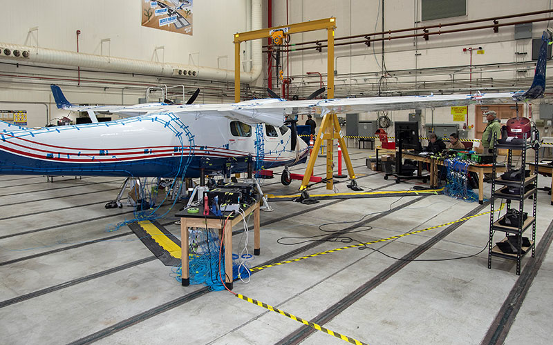
Ground vibration testing of NASA’s X-57 Maxwell electric aircraft
(Images courtesy of NASA)
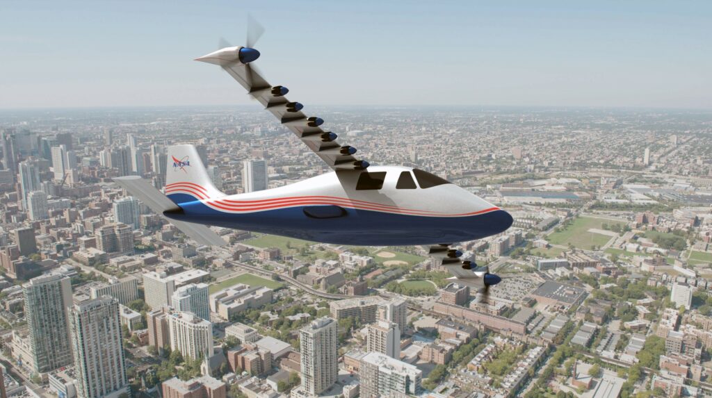
Electric propulsion is spawning aircraft with diverse and novel configurations (writes Peter Donaldson). The multiple motors, rotors, propellers and fans associated with distributed electric propulsion are shaping many complex and unusual forms in the quest to enhance lift and thrust, and to reduce drag through close aerodynamic coupling with airframes.
One of the most important processes in their development is ensuring that they don’t suffer from damaging vibration. To that end, NASA has used equipment from Hottinger Bruel & Kjær (HBK) to collect and process accelerometer data in ground vibration testing (GVT) for its X-57 Maxwell aircraft.
As Natalie Spivey, an aerospace engineer at NASA’s Armstrong Flight Research Center, explains, “We did this test before any flying to validate the finite element model used in our flutter analysis to make sure the aircraft has enough flutter margin.”
Flutter is uncontained vibration, which can be caused by forces applied to a structure such as a wing by normal airflow or turbulence. Of particular concern with propeller aircraft is whirl flutter, an aeroelastic phenomenon caused by the coupling of propeller aerodynamic and gyroscopic forces.
The X-57 Maxwell is based on a Tecnam P2600T, a small-twin normally powered by piston engines that is going through a staged modification process intended to culminate in a configuration with two large, wing-tip mounted cruise propellers and six smaller high-lift propellers along the leading edge of each wing, all electrically driven.
The GVT was carried out on the Maxwell in its simpler, Mod 2 configuration, with the piston engines replaced with electric motor mounts in the same positions, although the motors were not installed for the GVT. The aircraft must go through another GVT in subsequent configurations.
The tests carried out on the Mod 2 airframe involved single- and three-axis accelerometers arranged along both sides of the fuselage, wing spars, control surfaces, motor mounts and soft support frames for a total of 318 channels. The GVT set-up also included electromagnetic shakers for excitation with force transducers.
The positions of all these devices were carefully worked out with reference to the finite element model in the pre-test analysis.
To cope with the output from all these data channels, NASA used HBK LAN-XI data acquisition equipment arranged in four ‘mainframes’, of which two were 11-slot units located near the aircraft nose with the GVT control station and two five-slot units near the tail. Each slot housed a 12-channel LAN-XI 3053 data acquisition module.
As well as providing physical support and power, each mainframe provided data connectivity through a network switch, greatly simplifying the wiring.
Spivey notes that the vertical and lateral bending modes of the electric motor pylons proved tricky to measure. “Those are the first two structural modes that we really care about for whirl flutter, and they were hard to excite even when we were shaking right on them,” she says. “But that’s a good thing, because they are going to be hard to excite in the air too.”
With almost two years of post-processing behind them, Spivey’s team has finished updating the finite element model with the GVT data, conducted the final flutter analyses and the flight readiness review ahead of the Mod 2’s first flight next year.
“From an aeroelastic standpoint, we are just about ready to fly,” she says.
“As we move to the Mod 3/4 configuration with a whole new wing design and distributed electrical propulsion, that is a pretty complex whirl flutter problem because all those propellers interact with each other.”
However, the 12 high-lift motors will only be used in the low-speed regime of take-off and landing, while flutter usually happens at higher speeds, she explains.
Spivey says NASA is still analysing the Mod 3 configuration so that the team can create a finite element model that accurately represents the real structure. The model can then be used to predict the structure’s vibration characteristics.
“Out of the models we get mode shapes, and the wing mode shapes depend on the stiffness of the wing and the mass distribution along it,” she adds. “As you put more mass towards the tip, the entire wing is going to vibrate at a lower frequency but with more amplitude, which can be a concern for fatigue.”
After testing is complete on the Mod 2 version, the Maxwell will be shaken in its Mod 3 guise. “We will be putting the new wing on the same fuselage and pretty much repeating the entire GVT process,” Spivey says.
ONLINE PARTNERS

