


Fuses and circuit protection
Break points
Nick Flaherty reports on how new circuit protection technologies are meeting the challenges posed by increasingly powerful EVs
The EV market these days is seeing demand and development towards decreasing charging times, increased range requirements and a wider variety of vehicle models. All of this heightens the challenges on electrical system performance and design, particularly regarding circuit protection.
Decreasing charging times result in a demand for higher voltage charging and systems, with higher currents. The shift from 400 to 800 V brings major challenges for circuit protection on the battery. The manufacturers must consider the increased fault current in the protection component requirements.
As the motor power and current ramp up, so circuit switching and protection devices face higher requirements. They must withstand the higher operating currents and cycling requirements.
The decreased charging time requirement promotes higher system voltages, while increased range results in higher fault currents. The variety of EVs planned leads to a higher operating current requirement.
This is driving circuit protection requirements in several directions. High-voltage, low-current subsystems are increasingly addressable with solid-state resettable transistor switches, thanks to the advent of SiC MOSFET transistor switches.
The other drive is for high-voltage, high-current protection, where the conventional system architecture design involves a coordinated fuse and contactor solution in the power distribution box. The two must be coordinated to ensure coverage of the full range of possible fault scenarios, which can come from different battery states of charge and a range of underlying causes.
The third is to use a pyrotechnic approach, to physically cut the busbar in the event of a catastrophic incident such as a crash. Triggered by the same circuits as the airbag, this can quickly isolate the battery from the rest of the vehicle to protect the driver, passengers and first responders from short-circuits in the body of the vehicle.
This leads to a need for a new type of protection with fully coordinated circuit protection and switching called a breaktor. It can actively interrupt but also be passively triggered in case of power loss, and can improve functional safety of critical protection systems with the ability to reset itself.
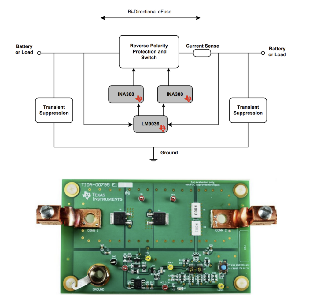
(Courtesy Texas Instruments)
Bidirectional efuse
A bidirectional automotive precision eFuse is an increasingly common approach in a vehicle. Traditional automotive fuses can be slow to respond and low in accuracy, which is an issue as the response time of a fuse is indirectly proportional to the safety of the system. Factors such as high delay time and high response time can lead to damage to loads and series path components such as wiring, semiconductors, and connectors.
To avoid such damages, vehicle platform designers are forced to add safety margins for components, which increases cost and weight of the vehicle. An eFuse with high accuracy and low response time increases the safety of system and reduces the need to over design components.
The fuse rating for an application is fixed. If the load current is directly proportional to system performance, then the fuse rating has to be set at the maximum performance with additional tolerances. This setting can cause the fuse rating to be anywhere from 50% to 80% above the normal operating current of load, which compromises the safety of the system.
Traditional fuses are available with standard values. Sometimes, it is difficult to get fuses for required current limit values, which leads to compromising by choosing the nearing fuse value to protect the circuit. This compromise is a risk for the performance of the system.
Frequent or long-running load operations lead to high power dissipation in series path components. The fuse will also heat up and will have a chance of failure while stressing at top load conditions. A self-healing eFuse can prevent this, limiting the need for frequent service calls.
An eFuse with the appropriate monitor and control circuits can also adapt and inform its condition to avoid such damage as the operating current of the fuse has to be set far less than the rated fuse current or melting current.
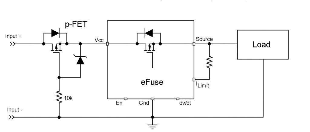
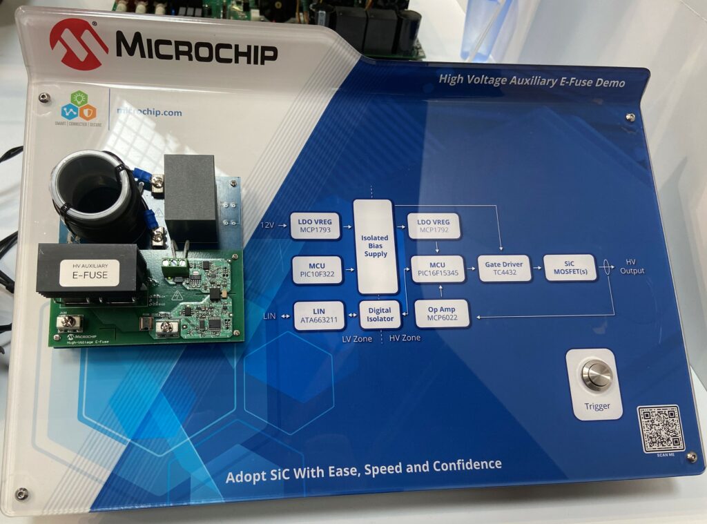
SiC MOSFET fuses
High-voltage electrical subsystems throughout battery and hybrid EVs require a mechanism to protect the high-voltage distribution and loads in the event of an overload.
The latest e-fuse system for 400–800 V battery systems based on a SiC MOSFET supports a current rating of up to 30 A. This can detect and interrupt fault currents in microseconds, 100–500 times faster than traditional mechanical approaches because of its high-voltage solid-state design.
The fast response time substantially reduces peak short-circuit currents from tens of kA to hundreds of amps, which can prevent a fault from resulting in a hard failure.
It combines a 700 or 1200 V SiC MOSFET with a current sensor, signal chain and digital signal processing in an 16-bit microcontroller. This has a high or low-side drive configuration with a short-circuit withstand time of 10 µs from the MOSFET’s 20 kHz switching speed. The sensing circuit operates at 9-16 V, while the HV side has an operating range of 200-900 V.
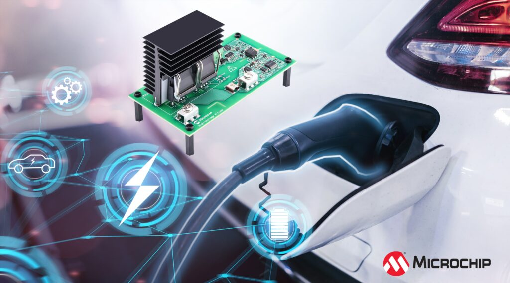
A demonstration board with all these elements allows designers to package an e-fuse into a vehicle to reduce the constraints for servicing, as the design can be reset from an ECU via a LIN comms interface.
The LIN interface enables the configuration of the over-current trip characteristics without the need to modify hardware components, and it also reports the diagnostic status. This provides a more flexible design of the BEV/HEV power system distribution, with higher visibility of the system status.
However, this dramatically increases the software and comms requirement when compared to a fuse or contactor system. The e-fuse demonstrator is supported by an integrated development environment (IDE) to enable designers to develop and debug software. This includes a LIN serial analyser development tool that allows customers to easily send and receive serial messages from a PC to the e-fuse board.
The design can be limited by the performance of the current sensor though. For large currents, this can be a bulky sensor with a slow response, hence the 30 A maximum for continuous current, although the current limit is configurable in the IDE. There are six variants of this HV auxiliary e-fuse design that support 400 and 800 V bus voltages and continuous current ratings of 10, 20 and 30 A with a switching frequency of up to 20 kHz.
Fuses and contactors
The conventional circuit protection solution of fuses and contactors has contradicting design requirements. Current levels in a vehicle can vary widely from under 100 A during regular driving conditions to as a high as 2 0kA or more during a short-circuit. This cycling during different driving styles is very different for a fuse or contactor designed for a steady-state current.
It is critical that the contactor performs the switching function during normal operation modes while the fuse is able to interrupt quickly during unsafe modes of operation such as overloads and short-circuits. Fuse and contactor coordination requires a seamless hand-off between two independent devices at a certain current level, which is not always possible to achieve.
Poor coordination can lead to reduced fuse reaction time, melted contacts, nuisance tripping and fuse fatigue. Late tripping can cause the contactor to weld, and creates a safety issue for the system components. Nuisance tripping is a safety issue as well, and can result in a loss of vehicle propulsion, which can be both a safety issue and result in customer dissatisfaction.
The physical nature of a fuse design means the coordination is a trade-off between fuse durability and fuse speed. Selecting a smaller rating equates to a faster reaction time, while the system current will cause higher fatigue and reduces the fuse’s lifetime.
As a result, selecting of a fuse requires expertise in the coordination challenge of the application, as well as fuse design and fatigue simulation capabilities.
(Courtesy of Adler Electronic)
Fuse design
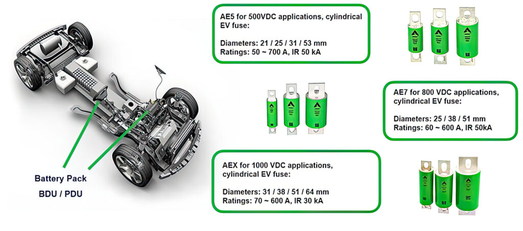
Melting fuses are inherently safe, and in the unlikely event of an over-current they interrupt the system. They are being developed for systems carrying working currents of 100 to 500 A above 500 V, where the melting and arcing time depend on the current.
For a current sensor for 300 A today the only solution is an inductive coil, where it can take up to 2 s to get the current data. A 500V fuse can carry several hundred amps and trigger if there is a 3-4x current with a response in the order of 1 second; if the short-circuit is high, for example 10,000 A, the response is typically 2-3 ms.
The preferred material for a high-performance fuse is a silver sheet, as it has the lowest resistance and a higher conductivity and better resistivity than copper. Copper tends to oxidise as the currents cycle, so the ageing behaviour for silver is much lower. Silver is more expensive but it is more robust and has longer longevity. It is also more sustainable than copper.
Holes are punched in the sheet to create areas where the fuse will trigger, and these structures are different for silver or copper fuses.
The cycling of low to high currents means the fuse heats and cools. That means small bottlenecks in the fuse get hot, and with copper the surface oxidises; copper metal is lost and the conductive area is reduced, so the fuse will then melt at lower currents.

Heat dissipation is a key part of fuse design. Using silver and a thicker copper terminal to conduct the heat away provides a thermal profile that is 20 ºC lower than other fuse designs. This helps to prevent triggering at a low current.
For DC voltages above 500 V, the fuse has to be longer to avoid arcing so it is necessary to interrupt a prospective arc. The highest heat is in the middle, and the further the centrepoint is from the terminals the longer the distance for conducting the heat away.
That means the design has to be open in the middle of the fuse with a pattern to create the weak point and then, according to the core section, the silver material conduction and the power rating, the weak point is calculated for a specific current.
The design of the structure in the fuse is constantly being improved, but for automotive designs the developers have to be informed if the design changes, as that changes the safety certification.
The ISO standard 8820-8 for cycling is limited to 450 V at the moment, but a newer standard for fuse testing, UL 248-20, covers fuses for up to 1500 V DC.
EV electrical architectures are being developed for 800 V DC systems in Europe and North America, while vehicle developers in Asia are pursuing both 500 and 1000 V DC systems. However, since the European Low Voltage Directive 2006/95/EC is defining 1500 V DC as the upper limit, there is unlikely to be a requirement above 1.5 kV.
A melting fuse is used alongside a DC contactor for a resettable system. If there is an overload but not a critical situation, the DC contactor will respond first and can be reset by the ECU. However, when the short-circuit is high, the fuse takes the responsibility for opening the circuit as the second-level protection.
Other melting fuse designs can use a bi-metal silver and copper structure to save cost. Analysis of a 500 A fuse with a 200-300 A current with a bi-metal fuse element shows the temperature variation from the cycling leads to expansion that causes microcracks, meaning the fuse cannot be used reliably.
This performance can be determined by thermal sensors that follow the performance during testing and by using a bypass diode over the fuse. If a microcrack occurs, the resistance increases from around a mΩ to over 10 Ω, and this is detected through the diode.
(Courtesy of Eaton)
Pyro fuses
A potential solution to the durability issues with fuses and contactors is a pyrotechnical switch. This is a triggerable circuit protection device similar to an airbag that relies on a controlled explosion to severe a conducting busbar. Pyro solves the coordination challenge but relies on accurate triggering rather than the passive reaction of a fuse.
The additional components must ensure a reliable triggering including potential failure modes in the electronics, which involves functional safety considerations.
Pyro fuses can be used instead of a contactor for low-level voltages, but they are not inherently safe as they require a signal. But they can be independent of the fuse and can be set to trigger with any current from a current sensor.
At over 3000 A DC, a contactor will break down and the current has to be then handled by the fuse. The pyro fuse takes a different approach, using the signal from the airbag’s ECU to trigger a pyrotechnic ignitor. This punches through the busbar to physically sever the connection.
Mature technology used for airbags can be combined with a fuse to provide isolation in the event of an accident. If the airbag ECU gets a high current signal, for example 2000 A, it can trigger a local fuse. The fuse can also use the airbag signals in the case of an accident to insulate the battery from the car body, using a piston to cut the bus bar.
This a complementary function of the airbag to protect the EV electric system. There is a small punching hole in the busbar to make sure the cutting area will be within the marked zone.
(Courtesy of Microchip)
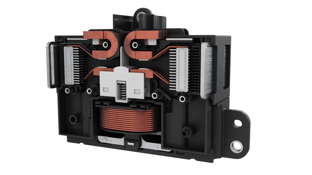
The breaktor
Over the past 10 years, almost every EV design has used a fuse and contactor for circuit protection. However, with the increasing current levels and increasing cycling this is becoming a limitation. Higher currents can lead to the contacts in a contactor fusing so that they no longer operate when required.
There is a trade-off between speed and durability. If the fuse is physically too big, it can be too slow to operate, whereas a smaller one can operate faster but suffers from a fatigue risk.
The voltage only comes into play when you are breaking the circuit, so the coordination between the fuse and contactor is the issue at around 250-300 A of continuous current and above. That is a fluid boundary as there are a lot of different parameters where the duty cycle is important. What’s most detrimental is the cycling and the nature of EVs, so the device needs to be designed for different drive profiles and different drivers
This is leading to a new type of circuit protection system called the breaktor.
A fuse contactor will be designed for a pre-determined range of drive profiles – racing, traffic, long sustained uphill travel – so developers estimate those profiles. These can be unpredictable, and there is always an inherent risk unless a safety margin is built in, which in turn reduces the speed with which the contactor or fuse can operate and reduces the safety margin, so it is a delicate balance.
The limiting factor is the contactor, as if the fuse is too slow the contactor can weld close or even explode with the high-voltage arcing between the contacts as they open.
The breaktor is a current sensor, so as soon as the current of the threshold is exceeded, which is typically 1600-2500 A, it will sense that and deactivates a 12 V coil that is keeping the contact closed so that the switch opens. A second mechanism uses the levitation of the contacts to keep them open.
In normal switching operation, the driver coil closes the contacts powered by a 12 V supply to switch the device on and falls back into off-mode when the supply voltage drops off. The breaktor constantly monitors the current levels with the onboard current sensor and shuts off the power to the driver coil once an overload condition is detected. The trigger’s over-current level is adjustable.
For short-circuits, the breaktor detects the condition in less than 1 ms and disconnects the driver coil. This high-speed deactivation helps to prevent contact welding by using electrodynamic contact levitation to limit the current through to the system, counteracting the Lorenz force that holds the contactors together.
This effect is threatening in the case of contactor and fuse combinations, as the levitation of conventional contactors can disrupt the fuse reaction to the fault. In any fault case, after the respective safety checks, the breaktor can be re-activated.
That means there is no need to coordinate the operation of separate components, and rather than a time current dependency curve, the breaktor has a threshold trip current. This means that if the system can withstand 2000 A the developer can dictate when the breaktor operates.
Typically, the breaktor is in the battery pack, with one per vehicle and positioned as close as possible to the source of power. It is costly to replace a fuse or pyro inside the battery pack, but there are limitations to placing these outside the pack, with the longer run of unprotected cable outside the battery pack making the system more vulnerable to interference.
In a commercial vehicle with a series of inverters for multiple drive units and external fast charging there would be multiple breaktors in external boxes.
One issue with contactors is the different forces acting as the contacts repel and arc and snap back. The key is that the process of de-energising the coil occurs quickly, in 2-500 µs. This avoids the competing Lorenz force that can pull the contacts back together.
This approach has been shown to operate reliably, interrupting currents of 20,000 A multiple times. This repeatability is achieved with a separate protection system to manage the high-voltage arcing.
The protection system uses permanent magnets, so the arc can be stretched and elongated to move the arc away from the contact points to avoid degradation. It also uses 10 arc splitter plates to force a 1000 V arc through a series of lower voltage 100 V arcs that extinguish the arc energy.
The breaktor is resets when the power is re-applied, as the 12 V coil is activated. The more challenging question is when a reset is safe. For example, a hard short to ground means the issue needs to be fixed before the reset. Typically, the advantage is that it needs to be taken to a mechanic to fix, and the breaktor can be reset without opening the battery.
Sometimes, for example in a crash, it is also necessary to isolate the HV lines to the battery when there isn’t a short. In this situation, there is a separate signal from the BMS, air bag ECU or the internal comms manager to trigger the breaktor.
The breaktor is implemented as a two-pole device for the positive and negative rails in the battery pack, with each contact rated for 450 V to give an overall rating of 900 V. It replaces a contactor on each of the two rails, and a traditional fuse and often a pyro fuse. This provides benefits when included early in the design process, as the larger size of the breaktor unit means it cannot be dropped into a design to replace a contactor.
Most of the heat is shed through the connecting busbars so you can cool the device with the conductors, but there are versions that can be liquid-cooled or that use a passive heatsink. The cooled version is typically aimed at heavy-duty designs, where the current though the device is over 500 A continuous, but it also depends on the duty cycle.
(Courtesy of Eaton)
Sealed switches
There is also a debate over whether the breaktor should be sealed or unsealed. The biggest advantage with a sealed switch is that there is no moisture inside, but if a leak occurs the device cannot function properly. Sealed switches also tend to rupture when the temperature builds up.
An unsealed switch needs a very fine particulate filter on the device, which requires more sophisticated validation testing. It needs aggressive accelerated environmental testing for the life of the vehicle, in conditions of salt spray, temperature and humidity to ensure correct performance. A silver oxide-based material is used for the contacts to ensure high conductivity, while the oxide layer prevents sticking. This has already been proven in industrial systems.
New versions of the breaktor are under development for megawatt charging and 450 kW fast chargers.
Advanced circuit protection
Circuit protection can cover the full range for overloads and short-circuits, as it can actively interrupt a system short for quick response time, and also passively interrupt in the event of system power losses.
This improves the functional safety of the EV protection system, and includes the ability to be reset by way of controls for service convenience. It also eliminates HV busbars and auxiliary voltage harnesses in the system, owing to the reduced number of overall components and connections in the system protection architecture.
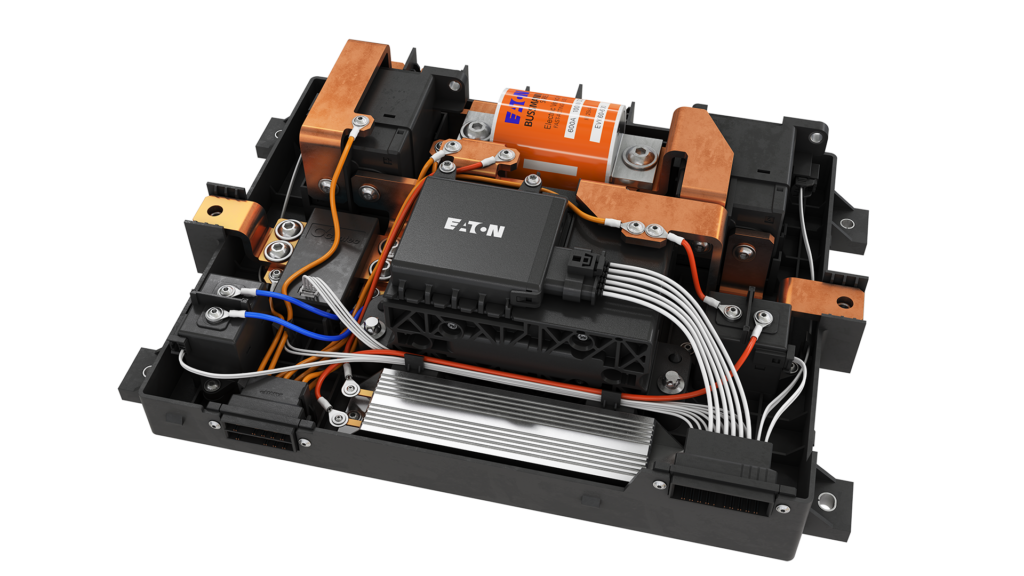
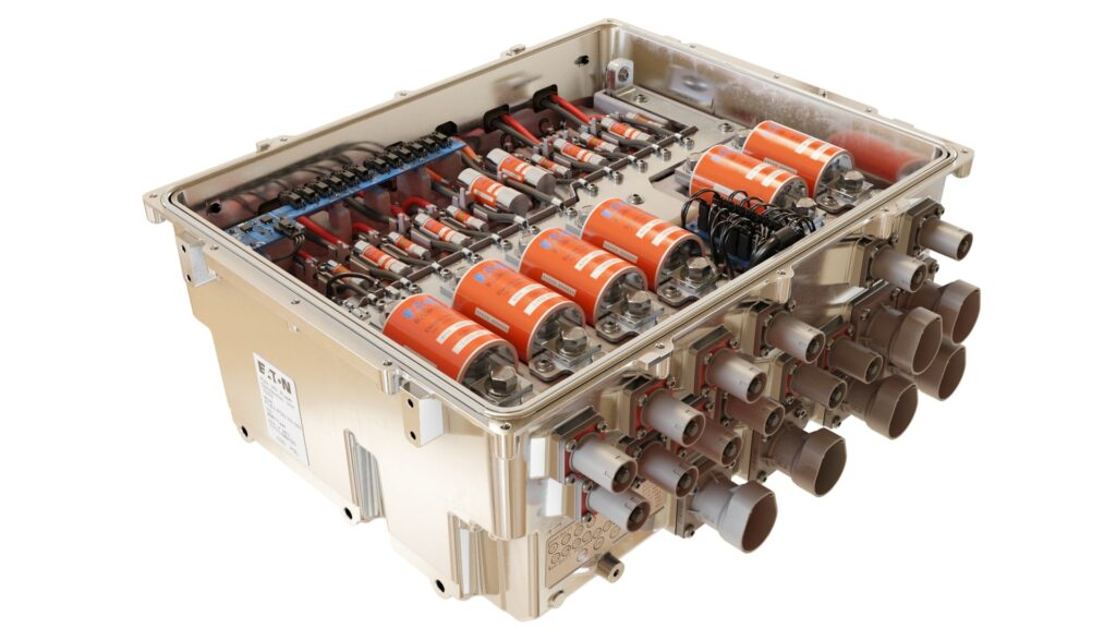
Battery disconnect unit
The battery disconnect unit (BDU) is designed to efficiently distribute power throughout the EV system. With the integration of a breaktor, the BDU provides improved quality and simplified architecture by combining current switching and resettable bidirectional short-circuit protection with fast actuation up to 900 V.
Using a breaktor replaces 15 components from the BDU assembly, as the breaktor’s integrated coil driver, economiser and the sensing/triggering circuit reduce the overall complexity of the design.
Conclusion
Despite the development of solid-state switches and integrated breaktor systems, fuses can still be considered viable solutions for EV protection. The design and application expertise will help to identify applications where a fuse and contactor system can be fully coordinated or whether a circuit protection system such as breaktor should be considered.
Alternative pyro technology solves the coordination issue but introduces new challenges to the application and system design with regard to its need for active triggering.
Acknowledgements
The author would like to thank Kevin Gizada at Eaton, Stefan Nitzsche and Peter Ng at Adler Elektronic, and Clayton Pillion at Microchip for their help with researching this article.
Some supplier of fuses and circuit protection systems
China
Hongfa
+86 592 6196710
ww.hongfa.com
France
Mersen
+33 1 46 91 54 00
www.mersen.com
Germany
Adler
Wurth
+49 34207 97 36 36
+49 7940 15 0
www.adlerelectric.com
www.wurht.com
Japan
PEC
+81 0584 91 3131
www.pecj.co.jp
SOC Fuse
+81 3 5420 1011
www.socfuse.com
Netherlands
NXP
+31 40 272 9999
www.nxp.com
USA
Altran Magnetics
Bel Power Solutions
Eaton
Knowles Precision Devices
Littelfuse
Microchip Technology
+1 815 632 3150
+1 630 705 6000
+1 269 342 3000
+1 630 250 5100
+1 773 628 1000
+1 480 792 7200
+1 815 632 3150
www.belfuse.com
www.eaton.com
www.knowelscapacitors.com
www.littelfuse.com
www.microchip.com
Click here to read the latest issue of E-Mobility Engineering.
ONLINE PARTNERS

