")


")


Thermal Management 2020

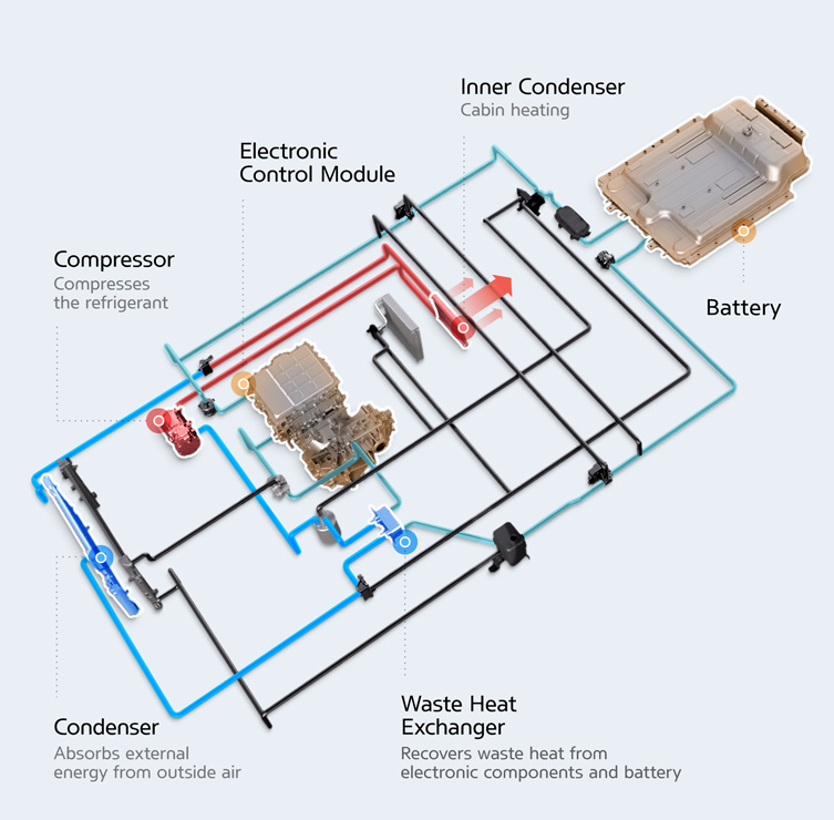
(Courtesy of Hyundai)
Peter Donaldson reports on the methods and materials for keeping EV batteries and other components in their optimum temperature range…
Transfer list
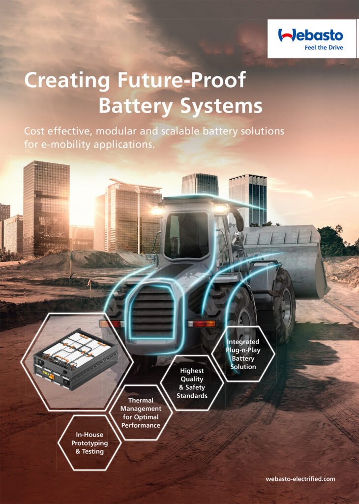
Thermal management is the art and science of moving heat energy around to keep various components of a vehicle – and its occupants – at safe, efficient and comfortable working temperatures. It can be thought of as the key to maximising the service life and performance of EV powertrains, whether they are pure electric systems or hybrids.
This discipline, which has been centred on the IC engine, is now adapting to EVs with a new set of cooling needs that in turn demand very different system designs and the use of specialised, thermally conductive materials. IC engine cooling systems have to manage extremely high exhaust temperatures, but while the use of batteries as the energy source eliminates that problem, it raises new issues such as keeping batteries within a narrow temperature range by cooling or heating them as necessary, and managing the electric conversion energy between batteries and inverters. Hybrids of course must cope with both sets of problems.
One specialist we consulted in connection with this article emphasises that engineers must be inventive and forward-thinking to make full use of new technologies, and to redesign systems from the ground up while maintaining or improving their safety, functionality and performance.
Engineers must choose the best solutions for motors, inverters and so on within the constraints of volume, weight and cost, while taking harsh operating conditions and long service lives into account. This can be a complex task, and one expert we consulted points out that factors influencing the thermal management of a motor, for example, include the specific heat transfer effect, process stability, price, weight, production rate and motor performance.
Another expert says customers expect solutions at the cutting edge of technology that are also very price sensitive. Developing solutions that meet both sets of demands is very challenging, and is driving efforts to simplify vehicle electronic architectures.
ICE vehicles can have hundreds of electronic control units that are connected by an extensive cabling system. On the other hand, Tesla for example uses essentially just one large computing unit, a philosophy that must be adopted for the thermal management systems of all modern EVs, the expert says.
Complex thermal needs
While the challenges associated with lithium-ion batteries tend to dominate discussions of thermal management – usually for good reason – the subject is complex, affects many interrelated areas and components, and should be addressed in a holistic manner, another specialist emphasises. Other components and subsystems, such as traction motors, power electronics and so on all have their own thermal management needs.
Furthermore, increases in the energy density, power density and charge-discharge rates of batteries, as well as the growth in performance achieved in all of them, increase heat output significantly. That heat has to be removed from where it will reduce efficiency or cause damage, and then rejected to the environment.
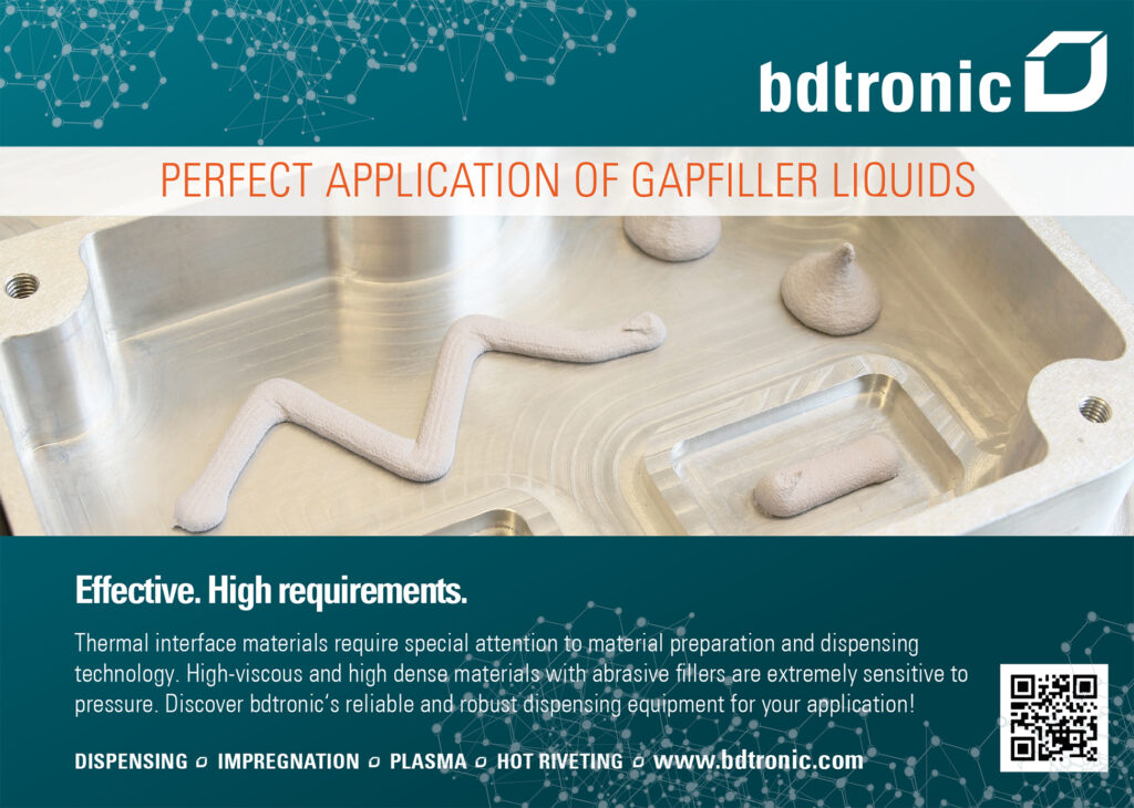
Dealing with these needs involves making choices between air and liquid cooling, the type of refrigerant and considerations surrounding immersion, all of which affect the design of battery enclosures. The use of heat spreaders, cooling plates and thermal interface materials (TIMs) must also be considered. Detection and prevention of thermal runaways is also critical.
There are significant hardware differences between the cooling systems in ICE vehicles and those in EVs, another expert points out. In the former, cooling mainly involves tubing, metal alloys and liquid cooling media such as water and glycols.
While these also have their place in EVs, the interfaces are much more complex in design terms, because in most cases the cooling media cannot get directly to the source of heat. As heat is produced by electric current, and these traditional cooling fluids are electrically conductive, a suitable interface that is electrically insulating but thermally conductive has to be created.
Another expert stresses that active cooling and heating cost energy, and while IC engines have an excess of it to run fans, pumps, compressors and so on, there is much less to spare in most EVs. Electric motors provide a big advantage in efficiency over ICE, but EVs still have to be much more energy efficient overall to compete successfully.
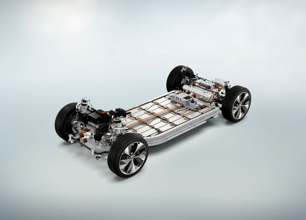
(Courtesy of Jaguar)
When designing a thermal management system for a new EV, another specialist says, the concept should encompass both cooling and heating, and involve as many heat transfer processes as possible to maximise power efficiency. It should include heating and cooling of the battery, of the cabin and then other elements from motors to power electronics without releasing energy to the surrounding air without first using it for something else.
Never waste energy
In the effort to manage heat while minimising losses, it is critical not to reject energy to the environment unless it really cannot be helped, one of our experts stresses. Perhaps surprisingly, the passenger cabin is an area in which there is a lot of room for improvement in this respect.
These days, the most common way of heating the cabin in IC-E cars is by blowing in air that has been warmed by passing over the heater core. Unfortunately, this air is then immediately extracted and rejected to the ambient air in the name of good ventilation.
In electric cars, however, heating of the seats and steering wheel is increasingly common because it provides an immediate sense of comfort on a cold day without having to heat the entire air volume in the cabin. As a bonus, heat from the seats and the wheel, and even window demisters, will eventually warm up the cabin as well, for a much lower overall expenditure of energy.
At the simplest level, the different thermal management requirements of key EV components amount to the fact that some need to be both heated and cooled in different circumstances, while others only need to be cooled.

While batteries have a narrow window of safe operating temperatures, motors have no real minimum temperature and will tolerate much higher ones than batteries. Power electronics such as inverters and converters likewise don’t have strict limits at the low end of the temperature scale, and their maximum temperatures lie between those of batteries and motors.
In modern high-voltage lithium-ion batteries, cell temperatures need to be tightly controlled within their allowable range to minimise degradation and avoid thermal runaway. At temperatures below 0 C, cell performance drops significantly because the chemical reactions slow down, while temperatures above 30 C cause degradation, and those beyond 40 C can lead to serious and irreversible damage.
While the temperature difference involved in cooling batteries is fairly low – they need to be kept at around 20-25 C – it is much greater for motors, as they can reach 200 C or more.
(Courtesy of Hyundai)
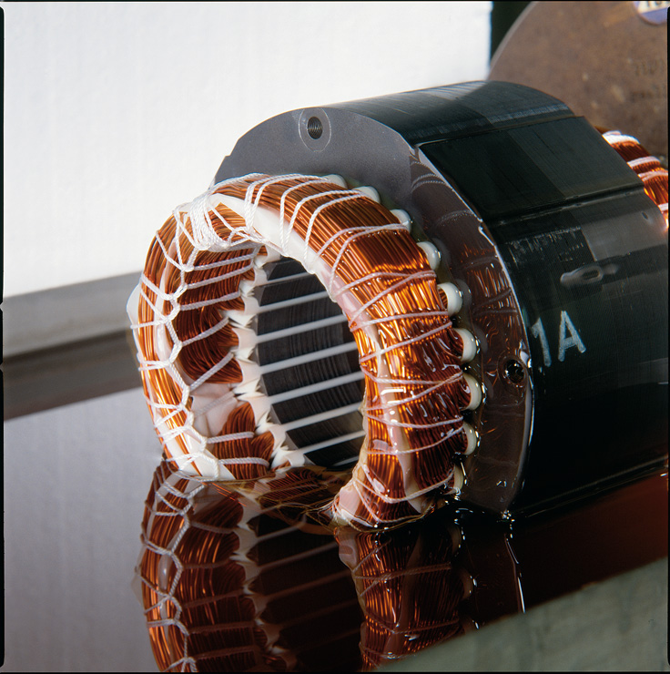
At the same time, motors in EVs must withstand a variety of environmental stressors. In addition to thermal shock and thermal ageing, they are subject to mechanical wear and ageing, as well as a wide range of power demand profiles associated with different types and styles of driving. Industrial motors, in contrast, are designed to work in narrowly defined environments within similarly narrow operating parameters – a conveyor belt motor running constantly at the same speed inside a factory is one example.
The most common cause of failure in motors is damage to the electrical insulation, while the operating temperature also has the greatest influence on service life. For example, a 10 C increase can halve the life of the insulation and, consequently, the motor. Efficient motors normally operate at 60-80 C at full load, and only those with specifically designed insulation can withstand larger heat loads for long periods.
Heat transfer mechanisms
Various thermal management techniques, materials and systems are available to cool some parts and heat others. Many options exploit the basic heat transfer mechanisms of conduction, convection and radiation.
Conduction and convection are the most important in all vehicles, although radiation is involved too. Conduction is the most important mechanism for extracting heat directly from the source, while convection is more important for removing heat from the cooling circuit, as it rejects the energy to the ambient air. Conduction, however, is the more challenging of the two from a materials designer’s perspective.
(Courtesy of Elantas)
The most common heat transfer media are air, liquids and polymer/ ceramic TIMs, with others such as phase-change materials, heat pipes and thermoelectric systems available as options for specific purposes.
As far as thermally conductive materials and their opposites – thermal insulators – are concerned, the most important differences in their properties stem from whether the component and/or heat source are static or dynamic. For example, a materials expert says a TIM for a battery, which doesn’t move relative to the rest of the vehicle, can be chosen on the basis of a different set of criteria from those governing a resin used in a high-speed motor.
In addition to the thermal conductivity of a TIM, another parameter that is crucial to both the material and the application is its thermal resistance, which is defined as its effective lifetime at a specified temperature.
Thermal conductivity
Thermal conductivity is expressed in Watts per millikelvin (W/mK). While gap filler TIMs used in batteries boast relatively high figures of 3 W/mK or more, they are unsuitable for electric motors because they are too viscous to get to where they are needed.
In contrast, the kinds of thermally conductive materials used in motors have lower thermal conductivities, of 0.5 to 1.0 W/mK, and have low viscosities to allow them to penetrate and fill very small voids; that makes them too runny to stay in place if used as a battery gap filler. The critical parameters for TIMs used in inverters and converters fall between those for batteries and motors.
One company specialising in TIMs, which are engineered to transfer heat from components into cooling media, emphasises the importance of understanding the drivers of thermal flux – namely the temperature difference between the cooling medium and the heat source – and the thermal resistance. The latter is governed by the distance between the cooling loop and the heat source, as well as the thermal conductivity of the materials between them.
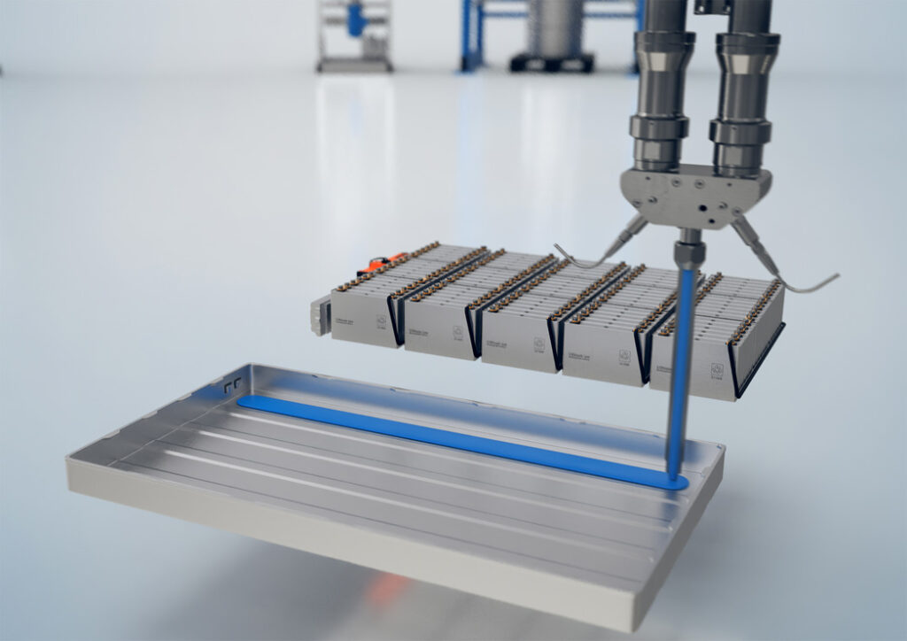
(Courtesy of ViscoTec)
The thermal conductivity and thermal resistance of materials, component design, mechanical stresses and thermal ageing all therefore have to be taken into account in the engineering process. The major challenge, says the company, is to align material applications and component design properly through working closely with designers.
While structural metals such as steel and aluminium are good conductors of heat, plastics are often relatively poor, and it is often necessary to insert specialist thermally conductive filler materials into battery cases and power electronics enclosures to maximise heat transfer from the component to a cold plate, for example.
These materials are often powdered or granulated compounds such as aluminium oxide (alumina) in a polymeric matrix such as silicone that enables them to flow into tight, hard-to-access spaces and cure in place to provide good paths for heat flow and the ability to withstand shock and vibration.
Another TIMs specialist points out that reducing the weight, density and bond line thickness of these thermally conductive gap-filling materials is desirable to help compensate for the extra weight and volume of high-energy batteries.
For suppliers of these materials, that means formulating low-density TIMs that can be applied in very thin bond lines to give vehicle engineers more freedom to create thinner, lighter structures. Naturally, TIMs used in these applications must be good electrical insulators.
From the point of view of battery pack manufacturers and assemblers, it is also important to make TIMs less abrasive, to reduce wear and tear on their pumping and dispensing equipment. This can be done by making the particles of the bulk material – aluminium oxide, for example – as spherical as possible.
Adding other substances such as boron nitride or zinc oxide to the mix improves thermal conductivity without making the material any more abrasive. These materials have different densities, from aluminium oxide’s approximately 4 g/cm3, boron nitride at 2.1 in hexagonal form and 3.45 in cubic form, to zinc oxide, at 5.606 g/cm3.
The polymers used are also changing as industry moves away from the use of silicone in manufacturing environments to avoid contamination that can cause problems such as disruption to adhesive bonding, soldering, coating and wire bonding. Silicone is still regarded as the dominant polymer in TIMs but others, including acrylics and polyurethanes, are coming into use.
Contact resistance
One of the most important properties of these polymers is low contact resistance, to minimise any hindrance to the flow of heat from a component into the thermal interface material, then to the cooling system’s working fluid and eventually to the heat sink.
This contact resistance is affected by the thermal conductivity of the polymer, the thickness of the layer between the alumina particles and the heat sink, which is another reason why polymers that can be applied in very thin layers are desirable. Also, when TIMs are applied in very thin layers, the bulk conductivity of the filler plays less of a role in the overall conductivity of the TIM, as contact resistance starts to dominate.
Most modern TIMs provide an overall value of 5-7 W/mK, as the bulk alumina’s 12-38.5 W/mK is reduced by mixing it with a polymer with a typical value of 0.2 W/mK. This, the specialist explains, is why customers should judge TIMs by overall conductivity, bond line thickness and contact resistance, not just the conductivity of the bulk filler material.
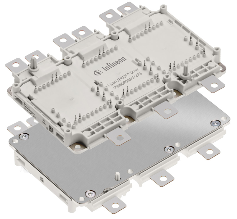
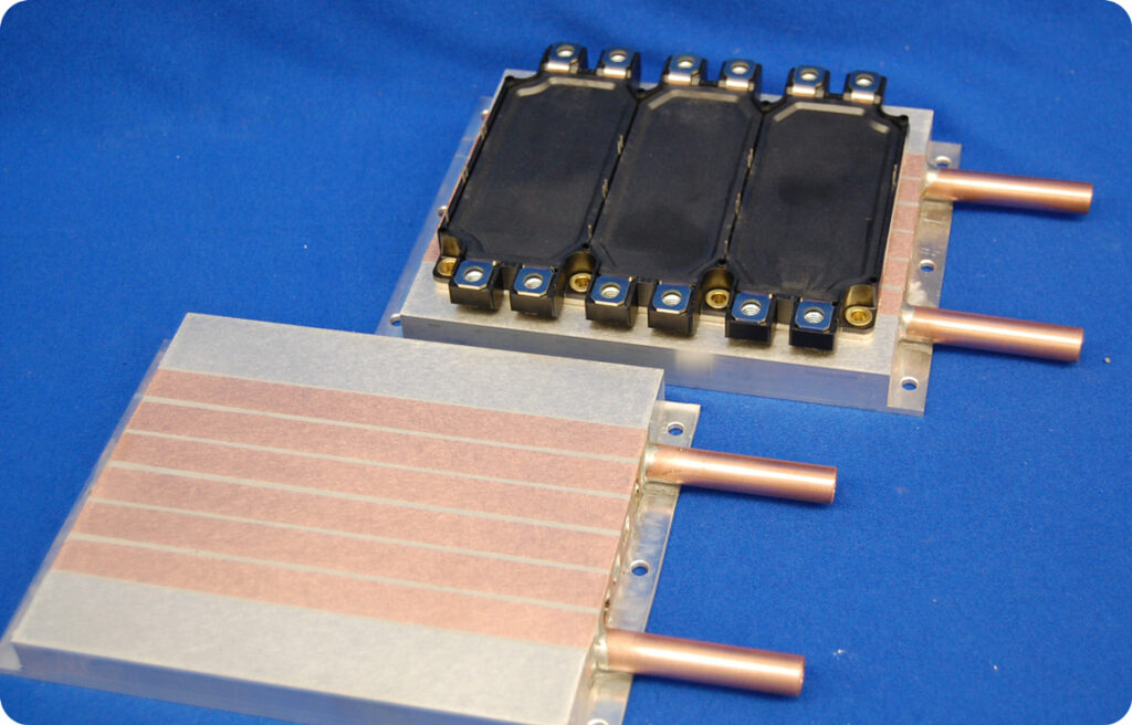
(Courtesy of Infineon)
Air cooling is relatively simple and inexpensive, but from an efficiency standpoint it is best used in applications where it is not practical to recover the energy, such as in conventional friction brakes used in an emergency where regenerative braking won’t stop the vehicle quickly enough.
However, to make savings in space, weight and cost, cooling systems are engineered for optimal cooling of batteries and inverters from the same cooling loop, which generally means liquid cooling. Liquid is arguably the most convenient way to transfer heat, particularly when some parts of the system can use the waste heat from others. In cold climates for example, batteries might benefit from the heat produced by motors and inverters to keep them up to temperature.
Modern inverters generate high heat flux while conditioning the power to run EVs, so they add an extra layer of complexity to the thermal management problem because they have to work closely with batteries – and in close physical proximity to them. They have different cooling needs, however, a liquid cooling specialist says.
While the key to battery thermal management lies in maximising the surface area that can be cooled uniformly, inverters have localised high power-density heat sources that have to be addressed by systems that spread the heat out as they cool the component. Also, inverters must be cooled to below certain critical temperatures to optimise vehicle performance.
Shared cooling loops
While it is easier for different systems such as these to share a cooling loop if they are physically close together and operate at the same temperature, different temperature requirements don’t rule it out, thanks to the growing sophistication of solutions designed to accommodate the needs of batteries, inverters and converters together.
Aside from packing all the required capabilities into the allowed size, weight, power and cost budget, reconciling the differences between the cooling requirements of these components is the biggest challenge to developing unified cooling loops for them, the liquid cooling specialist says. The key lies in cold plate design.
Cold plates in such fully optimised liquid systems are typically tailored for cooling hotspots or to maximise the contact surface area. As they are in such intimate contact with vital electrical systems, often running at high voltages and currents, it is vital that these cold plates are robust and tested thoroughly to ensure they are reliable, extremely durable and don’t leak. For the same reasons, connectors, pumps and hoses have to be just as reliable, but they must also allow for ease of maintenance as many of them are service items subject to wear and tear in normal operation.
TIMs and mounting hardware have to be designed to minimise any heat losses in the system between the heat source and the heat sink to maximise heat dissipation and prevent any thermal build-ups in inconvenient areas along the way.
As the volume available for cooling systems is at a premium in most vehicles, heat exchangers have to be designed to dissipate heat as quickly as possible in small spaces.
Modern shared-loop liquid-cooling systems can also integrate additional technologies such as heat pipes, advanced engineering materials, fans, blowers and heat sinks with new types of fi ns.
Because uniformity of cooling is vital to the health and longevity of batteries, this is one of the main drivers behind maximising the surface contact area of cold plates. In batteries, the plates don’t need fin enhancements, one specialist emphasises; the fluid that the coolant takes through the plate must ensure that the fluid covers as much surface area as possible, including the peripheries.
Some battery packs also contain areas of differing potentials in which a dielectric material must be used in combination with a thermal pad.

EV batteries tend to be large, so cold plates to cool them tend to be big items. They also have to be slim, however, to maximise the volume left for cells in the pack, which affects their manufacturing. The specialist emphasises that die casting is not a viable option, and that stamped aluminium with shaped flow passages is a better choice. In many applications, cold plates also provide physical protection, so they have to pass shock and vibration tests.
Inverters generate a large heat flux, and the thermal interface to the cold plate accounts for almost half the heat loss. That means specific mounting and interface materials must be used to attach the plate to the inverter and provide high compression loads with thin, high-conductivity TIMs.
Advanced materials for thermal management of motors have been used for high-performance sportscars, in which encapsulants with thermal conductivities of 1 or 2 W/mK are applied. While the process is effective at eliminating voids to maximise contact, it does not scale up well for mass production compared with conventional impregnation processes that use materials of lower thermal conductivity, of around 0.2 W/mK.
Recently, however, impregnation materials that achieve 0.5-1 W/mK have come onto the market. These can be applied in manufacturing using existing mass production equipment, and although the resulting thermal performance is not as good as that achieved with full encapsulation, it is better than that achieved with materials suited to application by conventional methods such as impregnation of windings by trickling, an expert says, and enables electric machines to run up to 30% cooler.
Future directionality
In future, cooling systems are likely to include a supplementary means of storing excess heat, an expert comments, suggesting conversion to electricity for storage in capacitors, the use of a compound such as a salt or phase change materials (PCMs) such as wax to even out temperature spikes.
(Courtesy of D6 Industries)
To achieve such peak flattening, PCMs can be used alone or in combination with liquid coolant in a battery pack, for example, where there is a heat peak caused perhaps by rapid acceleration. Here, the spike in heat energy would change the wax from a solid to a liquid instead of increasing the local temperature and overwhelming the cooling system. After the spike has passed, the wax would then change back to a solid, releasing the energy to the rest of the system more gradually.
The thermal conductivity of materials is the main influence on thermal management, so new high-conductivity materials will directly increase efficiency. A possible development direction is non-isotropic materials whose thermal conductivity is directional, one of our experts notes.
He suggests that graphene could be a candidate if given a directional bias by external electric fields or an extrusion process. With directionality engineered into the TIM, much greater heat flow could be achieved for a given weight and volume of material, allowing even greater power densities in batteries and power electronics.
Heat is an inevitable by-product of converting energy from one form to another. The same is true when stepping voltages down or up or converting currents between AC and DC – no energy conversion process is 100% efficient. The energy lost ends up as heat, and the laws of thermodynamics show that not only can we never come out ahead, we can never break even either. That doesn’t mean however that we should stop trying, and worthwhile gains are still to be had.
Acknowledgements
The author would like to thank Mario Kuschnerus and Ralf Homann at Elantas Europe, Lars-Goran Rohrbeck and Dr Christoph Lomoschitz at Axalta, and Jens Lange at Von Roll Automotive for their help with researching this article.
References
“Advancements in Liquid Cold Plates & Liquid Cooling Systems for eMobility Applications”, Boyd Corporation, AAVID division, July 2020
ONLINE PARTNERS


