


")


")


Testing and simulation systems
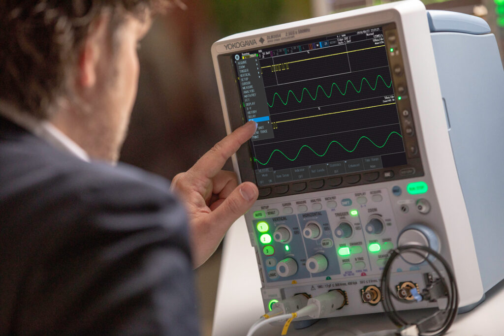
(Courtesy of Yokogawa)
Trial Periods
Rory Jackson explains how various test methods work, why they are important and how EV developers can set up their own facilities.
Throughout the course of electric and hybrid vehicle development, it is important to remember that the overall system consists of a number of different parts, each in need of specialised tools for analysing and evaluating how they perform individually and as part of the whole. Early on, simulation programs can set a baseline for how components are selected, how they are interconnected throughout the vehicle, and how they might be expected to perform and interact.
Those expectations can be tested and validated using a range of test and simulation systems, either acquired and used in-house or outsourced to partner companies with their own solutions, who can measure the performance of motors, batteries, power electronics and other subsystems against manufacturers’ specifications and international standards.
Simulation software
Simulation programs should typically model two key areas – the physics of the vehicle and its components (such as the forces, movements and power being generated or used by them), and a virtual environment through which the vehicle being simulated can be ‘driven’.
The former typically requires extensive libraries on commercially available electric parts such as motors, resistors, inductors and capacitors. Having this data on other items such as engines, gearboxes and suspension systems can also be critical to accurately gauging the overall performance of the vehicle before real world testing can take place.
The latter provides a similar service to the finite element analysis (FEA) programs used widely to simulate loads and stresses on single components. However, vehicle simulations should integrate a physics engine with multibody mechanics, which will also model the differing dynamics of interconnected chassis components, and the joints and hinges between them, with reasonable accuracy. This provides value above the general limitations of FEA.
The libraries ought to contain publicly available specifications on each part or subsystem. General specifications should be covered, such as dimensions and weight, as well as more specific figures for each part, such as electric motor torque, rpm and power.
Further series of data detailing key performance variables, such as changes in torque or efficiency across different rpm levels, might be obtained from suppliers for inputting into the simulator programs.
Data libraries can enable quick swapping in and out of different motors, gearboxes and other parts. This allows rapid experimentation with different powertrain configurations, to evaluate different concepts in pursuit of project targets, without having to obtain the actual components in the real world or having test results influenced by their overuse.
Sufficient customisability of simulation platforms should ensure, however, that in the absence of exact specifications, EV/HEV manufacturers can pinpoint which subsystem characteristics fit the performance envelope of the kind of vehicle they wish to model. This might include models for inferring the performance characteristics of an electric motor based on a short, publicly available datasheet for example.
Customisability could also enable vehicle designers to set flexible parameters throughout the powertrain while maintaining the driving speed and efficiency of whichever type of vehicle they are looking to develop. They can then approach developers of electric motors, battery packs and power electronics to request customised parts for engineering their EV/HEV solution, or customise them themselves if they have the necessary competencies.
Once the EV/HEV and its powertrain have been virtually configured, a wide range of simulations can be run with it. This might include testing the acceleration, the drive cycle, the ride and handling and so on. High-fidelity models of real-world locations can be generated, including racetracks or public roads.
Current simulation software can also go further than test driving the vehicle and examining multi-body dynamic interactions, by investigating the electrical, magnetic and thermal behaviours between the vehicle and its powertrain.
This includes modelling any thermal losses caused by the varying inefficiencies of different components. These are particularly critical for thermal management studies, as losses can be pre-emptively coupled with cooling or heating systems across the virtual vehicle to improve performance efficiency in different climates before it comes to real-world prototype testing.
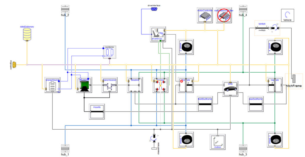
(Courtesy of Claytex)
Thermal simulation can also model the re-use of excess heat or cooling by directing it into the cabin, as heating or air conditioning.
Just as important is the ability to introduce and model faults. If manufacturers want to gauge how a vehicle or its safety functions perform in response to a leak in a cooling system pipe for example, or the failure of a battery cell, these can be introduced into a simulation at will.
Dynamic modelling of motor mechanics can also be vital. Static models of motors are good for racking up fast simulations of drive cycles, but by improving the degree of fidelity in motor behaviours, designers could for example introduce the switching effects coming from the power electronics.
This and other improvements could be key to the analysis that vehicle manufacturers might want to perform, such as looking at voltage ripple and voltage oscillations along the power cables, and how they translate to a vehicle’s driveability and performance.
In particular, many vehicle manufacturers whose core competencies have historically revolved around ICE powertrains want to be able to analyse how the electric motor control impacts the way a vehicle drives.
Any sharp change in what is demanded of the electric motor could potentially give a deeply uncomfortable shunt to the driver or other occupants of the vehicle. Worse, it could generate oscillatory acceleration and loss of vehicle control.
As might be expected, this can also be useful for motor manufacturers looking to predict the sorts of loads a new motor might experience, as well as what the torque profiles are, in case they see some large torque spikes that they need to account for in the shaft or bearing designs.
Such is the diversity of modern simulation software that motors can also be simulated and modelled across the gamut of vehicle types, to examine the virtual performance of a wide range of components and chassis. Realistically, the physics engines can model any physical device; the only bar is the depth and range of vehicle specific application libraries that have been produced for them.
Typically the software will also take care of programming issues such as specifying the load order of calculations regarding the physics and mechanics of the vehicle.
Naturally there are certain limitations to what simulation tools can accomplish. For example, while aerodynamic loads can be applied to a simulated vehicle, flows of air over the chassis cannot be measured. For this, conventional computational fluid dynamics or wind tunnel testing might be more suitable.
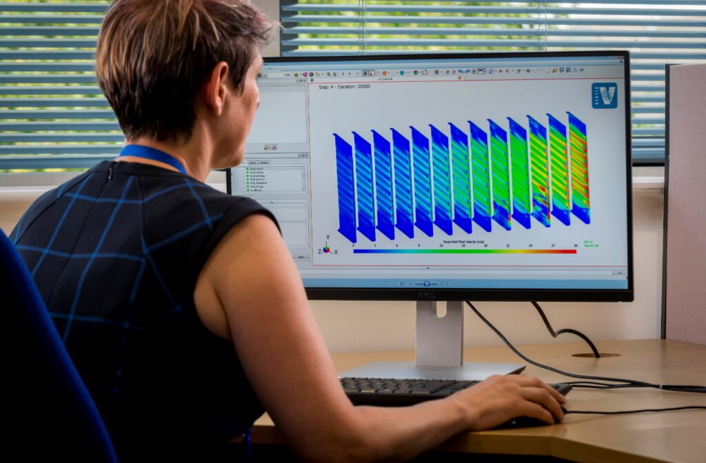
(Courtesy of Ricardo)
Potentially the biggest gap between simulated testing and road testing is a lack of data on the physics of tyre models, which remains difficult to simulate closely, largely because of the internal complexity of tyre models. Advances in FEA to model down to small mesh sizes for the internal parts of tyre belts continue to be made, however, to make characterisation of these mechanics more accurate.
That should lead to better simulation of how EVs and HEVs handle slip, and the ensuing effects on temperature and behaviour of vehicles on different types of road. Such information is less important to dynamometer or test chamber examinations, but still extremely important ahead of track testing.
Battery testing
There are various battery testing rigs and equipment that are worth investigating, although large test service providers often use systems from a range of suppliers.
There is also a huge number of international standard tests for safety and other requirements. Some involve abuse test conditions, and thus significant thermal events, placing serious requirements on facilities and equipment.
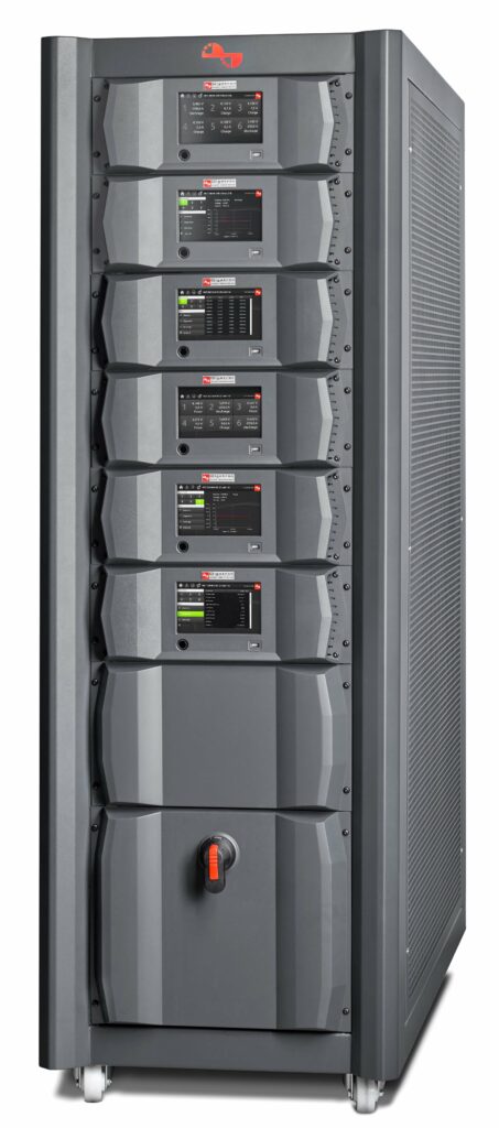
The Regenerative Universal Battery tester is designed for testing lithium, NiCad or NiMH batteries up to 20 C
(Courtesy of Digatron)
An important consideration is whether equipment is actually legal for use in different parts of the world, for example whether a battery cycler made in the US can be adapted and CE-marked for use in Europe.
Testing batteries with cyclers and other analysers is critical for understanding how they age, degrade or fail over time, what the indicators of these processes are, and what triggers or influences them. Subjecting the batteries to conditions they would experience in the real world, but with controlled and repeatable parameters, is therefore key.
That helps to calibrate mathematical models of batteries, and helps design and validate packs before production. Occasionally this blurs the line between testing and simulation, and verifies that batteries perform according to the specifications given by battery manufacturers.
While battery analysers check batteries in service and predict replacement, battery test systems provide various functions, including lifecycle testing to simulate battery loading and verify durability. Much of the time, that involves repeated and automated charging and discharging of the battery to investigate capacity, internal resistance and self-discharge.
As with other components, environmental chambers and rate tables are critical for testing a battery’s tolerance to moisture, heat, vibration and shock. Many hours of tests must be repeated, as weak or damaged batteries can still behave like healthy batteries under certain conditions. For example, a strong battery with low charge can behave similarly to a battery that exhibits capacity loss.
Battery characteristics can also be thrown off by recent charges, discharges or lengthy storage, so these external factors must be identified before or during testing.

Leak testing
Leak testing involves investigating the water-tightness and air-tightness of components.
Different parts of an electric powertrain are subject to risks arising from the ingress of water due to splashing or immersion in it. The significance of these risks can be ascertained through leak testing during the development phase, to ensure that EVs and HEVs operating in wet or flooded locations do not suffer in terms of safety or function.
Batteries in particular must be evaluated using leak testing. When the electrolyte reacts with water, hydrofluoric acid can form, which can then cause further leak points or even destroy the battery cell. Leakage of any electrolyte from the cell can also harm people, potentially in the form of heavy metal poisoning. It can also decrease the capacity of the cell significantly over time, and hence its lifespan.
A range of tests can be conducted, meeting the requirements set under ISO 20653 standards for protecting electrical components in road vehicles against foreign objects or water, typically IP protection classes such as IP6k7k, IP6k8k or IP6k9k. Such tests cannot simply be transferred over from ICE leak tests though, as ICEs can tolerate a far higher degree of water ingress.
Potentially the broadest category is pressure testing, which as its name suggests involves subjecting the test item to a specified pressure level in a chamber. After a certain time has passed to allow stabilisation of the chamber and the item under test (and for potential leaks to occur), the leakage rate can be calculated.
Leakage caused by excessive pressure (compared with ambient pressure levels) is known as overpressure testing. If leaks from reduced pressure are being tested for, then the process is called vacuum testing. Absolute pressure testing is performed when the test item is subjected to absolute vacuum conditions.
Manufacturers must take care when pressure testing large battery systems, however, as strong forces on the battery housings can cause unnecessary damage to the sealing systems. On the other hand, and for obvious reasons, the pressures applied must not be too low.
Mass flow tests measure the volumetric flow of test liquids or gases that pass into a product over time owing to a leak (for example, cm2 of air per minute), thus measuring the integrity of parts and components. These tests are more often used for larger leak rates and test parts with larger volumes.
Power electronics
Using specialised power analysers is important for accurately measuring and recording the performance of inverters, converters and other electric powertrain components.
Oscilloscopes are often used to measure and graphically display varying signal voltages over time; the ideal choice might be a mixed-signal oscilloscope with eight channels to view input and output signals in threephase systems. Current systems can be used to evaluate a wide variety of signal buses including I2C, SPI, CAN, CAN FD, LIN and SENT, to accuracies as close as ±0.03% of the signals being
measured.
Simultaneous testing of multiple components or signal buses, as well as concurrently displaying multiple waveforms or analysis results across several windows (often two to four) is also increasingly offered. This allows faster validation of systems across different international standards for the performance of power electronics.
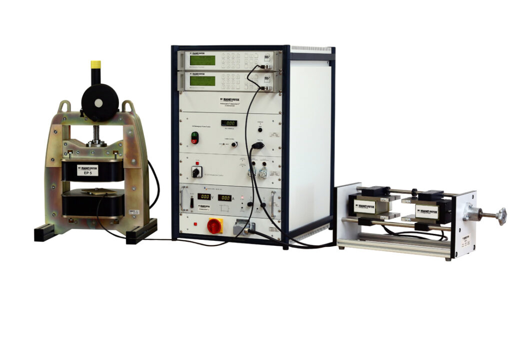
(Courtesy of Magnet-Physik)
Combining oscilloscopes with highcapacity solid-state storage devices is also recommended. The more data that’s available, the more reliable and detailed the analysis of performance trends will be.
Electric motors and powertrains
Despite the differences in speed, torque and power between electric motors and ICEs, the principles of testing both are quite similar.
A motor is attached to an absorber or generator, then run for many hours to understand vital characteristics such as those above, as well as thermal performance, the effects of friction and other influences on power efficiency. It also means looking at the durability of the drive systems, and conducting certifications tests.
That requires single- as well as multi-axis test facilities. Anything from a single dynamometer up to a fivemachine test facility might be needed to accommodate the requirements for individual motor or full powertrain testing.
The requirements of dynamometers can vary for electric powertrain testing. In some cases they must be capable of 25,000 rpm or more, to accommodate the higher speeds of electric motors made for fast road vehicles. For much larger, heavier electric vehicles, however, they should instead be designed for extremely high torque.
Other requirements can be reduced compared with conventional vehicle testing rigs though. In many cases, the supply systems for ventilation, cooling and fuel are no longer needed, unless a hybrid system is being tested.
A high-quality dynamometer must be validated for long-term reliability, given the speeds and torques of electric motors. Potentially the best type of dynamometer is flexible in its capacity, and can therefore be used to test highspeed, low-torque motors for cars and low-speed, high-torque types for trucks, so the dyno does not need to be swapped or reconfigured each time the unit under test is changed.
Combining high-speed and hightorque capabilities in a dynamometer can be extremely difficult, however, owing to the general trade-off between speed and torque. For example, a high-torque electric motor typically needs a heavier rotor, which is difficult to bring up to speed; the same holds true for dynamometers.
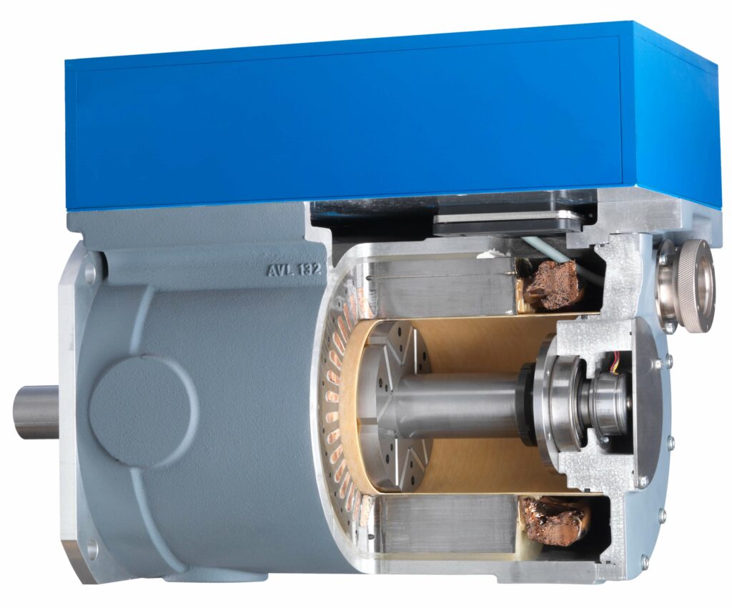
(Courtesy of AVL)
It is also highly beneficial to minimise torque ripple generated by a dyno, as when combined with the torque ripple of an electric motor at low speed it can result in measurements significantly at odds with the motor’s actual performance characteristics. Programming the dynamometer controller and designing the rotor to minimise asymmetries in magnetic flux can help reduce the variance in rpm responsible for torque ripple.
Before this, during the development of motors, testing the remanence and coercivity of the permanent magnets with a permagraph tool is important for ensuring they will provide the necessary level and lifespan of magnetic flux expected. For most motors, neodymium magnets will be used, and should show remanence levels of around 1.2-1.3 T, and coercivities of roughly 1600 kA/m.
Testing facilities
The increasing spread and output of the e-mobility industry is boosting the demand for test facilities, to the point where capacity is becoming a significant issue for many OEMs. Global EV/HEV manufacturers might find, for example, that they can fulfil targets for test operations and durations on systems in North America and China, but that there are bottlenecks in the ability to test their systems in Europe.
While it might seem like a simple solution to just ship vehicles and parts to test centres on other continents, this can be time-consuming and expensive. An alternative approach might be to build more test cells, but that can be even more costly and take even longer, without necessarily having a large enough impact on regional test capacities to justify the time and money invested.

A conventional test room (or test ‘cell’) for an engine or powertrain is traditionally built within a large bricks and-mortar facility. Repurposing an existing office building or warehouse will not suffice; preparing test facilities for EV/HEV components mandates figuring out exactly how much space will be needed for conducting different or difficult operations. It also means determining how many test cells need to be developed, where the cabling and piping will be routed, and obtaining investment planning and safety permissions.
For a test facility with enough capacity to justify the time and cost of building it in the first place, 18 to 36 months of construction time is typical. By the time it is built though, the technology or regulations might have changed (a risk across many high-tech industries), perhaps rendering some aspects of the building inappropriate for testing or meeting regulatory requirements.
Even if that doesn’t happen, the larger the building, the higher its maintenance, servicing and administration costs, creating further unwanted work and expense for test engineers.
However, a new solution is emerging in response to this shortfall in test capacity and the inflexibility of bricks-and-mortar facilities – transportable, semi-containerised test cells, which can be moved as demand moves, potentially on a year-by-year basis.

Building one of them requires some basic and limited construction, such as concrete groundwork in order to secure them in place (which might remain if the test cell is moved elsewhere in subsequent years). For electric powertrain and component test cells, typically the only interface needed is electrical connections; for ICE or some hybrid powertrains, a fuel connection might also be needed.
Although this type of solution has only been available commercially in recent years, a range of configurations is already available, including transportable test cells for two-wheel electric, hybrid, gasoline and diesel powertrain cells. This year should also see the first development of four-wheel powertrain transportable test cells.
Such is the modularity of these test cells that one designed for 1.2 MW EV testing can be effectively split into two separate 600 W powertrain tests. That means an end-user could use their cell for full vehicle testing 20% of the time, and for independent powertrain or subsystem testing and validation for the other 80%.
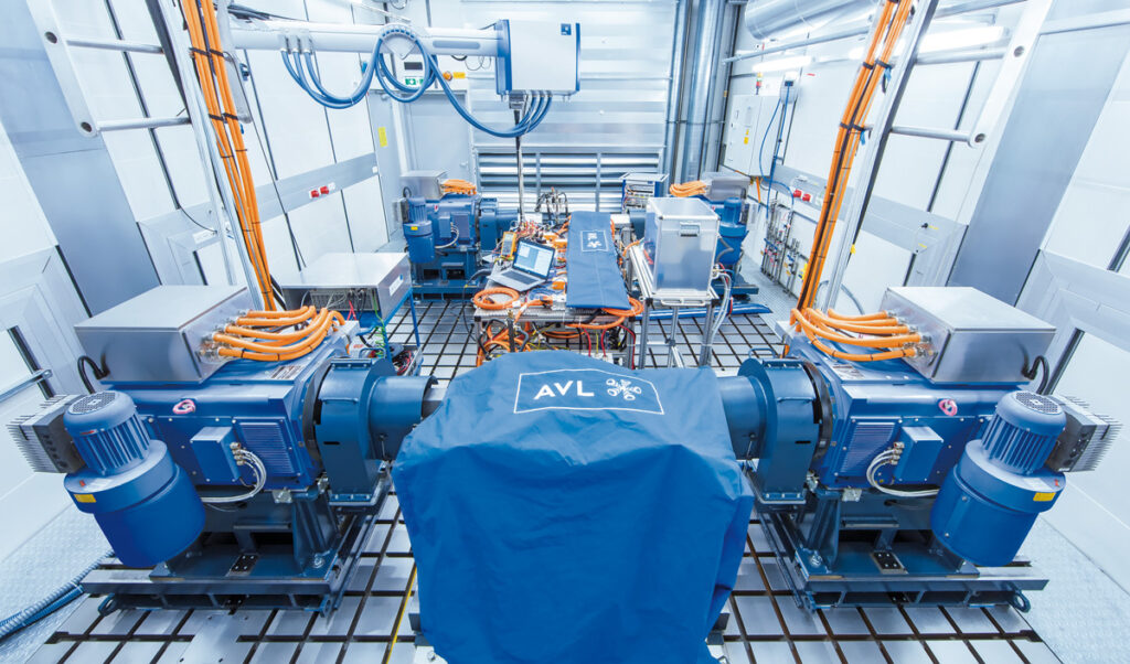
(Courtesy of AVL)
It could also enable simultaneous testing according to multiple standards or certifications, enabling faster international validation of a vehicle or part. A conventional building might not be able to re-route the circuitry or equipment necessary to enable any of this.
This provides a more cost-effective test cell for test engineers, and more flexibility for a vehicle manufacturer as they can more quickly evaluate the different kinds of powertrain they are considering for their EV or HEV.
A typical transportable cell for testing batteries would contain battery cyclers, which can also be designed modularly so that two 250 kW cyclers can be paired to create a single 500 kW battery cycler, for example.
At one end of the test chamber might be a room for environmental testing of the battery pack, and on top of it there would be infrastructure for cooling systems to feed air in and out of the room (built into modules so they too can be lifted into place), and at the back there could be a device room. That would house a test automation system, some extinguisher systems and so on.

Currently, these test cells can be built to EUCAR Hazard standard level 6. Level 8 is the maximum, for full explosion testing, while level 1 is testing with no associated hazards.
Level 6 protects against violent eruptions of gases or small flying objects within the cell, so a cell built to this standard tends to have stainless steel walls, and includes a gas eruption disc, which is ejected to allow release of gases from the cell.
Keeping these cells outside is not only important for transportability, therefore, but also for safety. For example, thermal runaway of lithiumion batteries can generate toxic gases. A 100 kg battery pack can burn for two days straight, and even attempts to deprive it of oxygen will not help, as it produces its own oxygen as it burns.
A test service provider or OEM can opt for one (or two) of these newer, more flexible and modular types of test cell for more cost-effective, incremental increases to their test capacity, without incurring the overheads of a large building. Doing so can also save money that could be invested later in a larger, bricks-and mortar facility.
Build times for this type of test cell can be as short as six to 12 months – potentially a third of that for bricksand-mortar test facilities – and they can be delivered by road or sea within a month or two, depending on the number being delivered and the distances involved.
However, for very large EVs/HEVs such as electric mining vehicles or construction vehicles, this would not be practical; a typical building-contained test facility would still be needed.
Conclusion
As the range of production electric and hybrid vehicles grows, rising voltages and greater autonomous capabilities will boost the need for more modular and more accurate test and simulation systems, pushing their capabilities ever further.
Acknowledgements
The author would like to thank Michael Dempsey and Alessandro Picarelli of Claytex, Alban Hemery and Isabelle Knauder of AVL, Harri Kervinen of Proventia, Friedrich Grupe of Digatron, Steffen Nabholz of Zeltwanger, Kelvin Hagebeuk of Yokogawa, Fredrik Wigh of Magnet-Physik, and Michael Bates, Pascal Revereault and Cedric Rouaud of Ricardo for their help with researching this article.
ONLINE PARTNERS


