


")


")

Radial flux motors
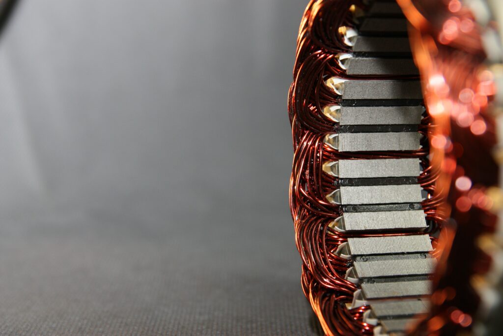
(Courtesy of Avid)
The latest trend in radial flux motor design is to boost power density while reducing cost. Nick Flaherty explains how it’s being done.
More from less
The radial flux motor is the workhorse of e-mobility. The basic structure of a static rotor (stator) driving a moving rotor in a radial magnetic field is used in different form factors and power ranges for all kinds of electric vehicles.
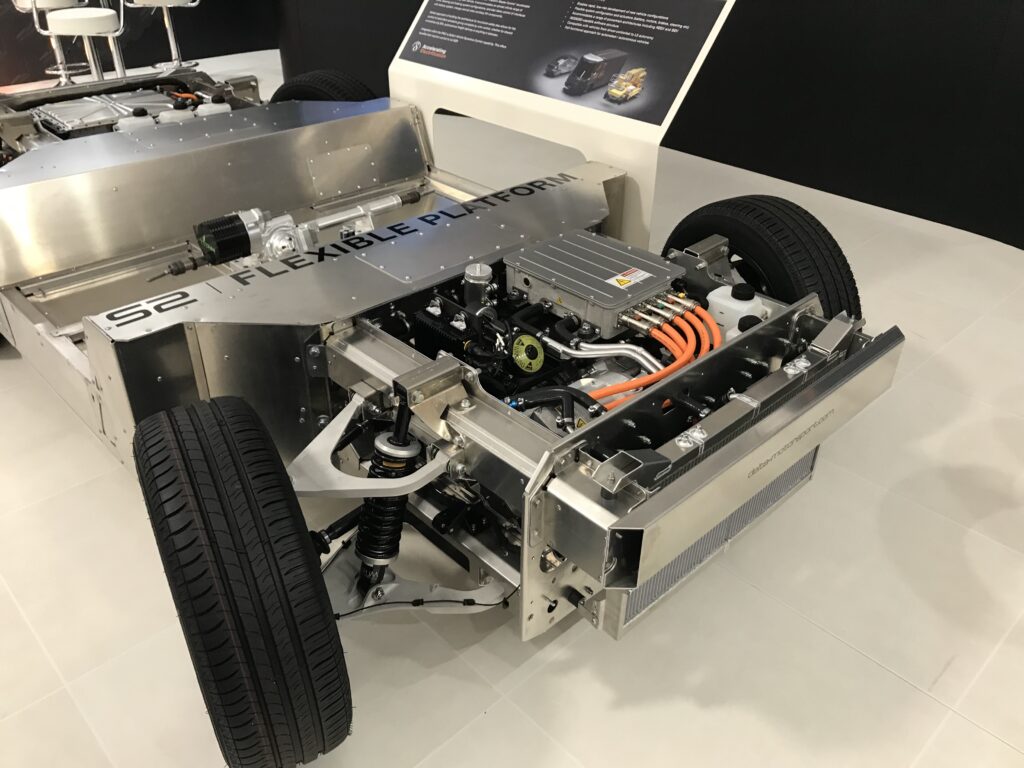
The flexibility of the radial flux design also has an impact on the design of e-mobility platforms. A longitudinal, or sausage, form factor with a simple gearbox can be the most economical way to drive two or even four wheels on a ground vehicle.
There are several types of motor. Motors with internal permanent magnets (IPMs) and surface permanent magnets (SPMs) can make use of the reluctance between the rotor and the magnets to boost the torque, while induction motor (IM) and wound field synchronous machine (WFSM) designs offer different trade-offs between power, torque and axle speed.
For an EV with 6000 Nm of torque, providing an axle speed for 155 mph requires around 2000-3000 rpm. With a single-speed gearbox with a high ratio this would provide a constant torque for one-third of the time and two-thirds at constant power. A radial flux runs well with a gearbox, and doing the torque multiplication in the gearbox means a smaller, lighter motor can be used.
All these motors can be implemented in one of two main form factors.
A pancake form factor might fit better into a particular platform design, and even fit into a wheel. The trade-off between having two inwheel motors with their associated cooling, and a single motor, is a key discussion for system architects looking at the balance of cost, weight and performance in ground vehicles.
The focus here at present is on the power density and cost reduction, which is largely down to optimising the materials used. High-field magnets use expensive rare earth elements, so reducing the size of those magnets is a key aim.
The form factor changes according to the amount of space, torque and speed, and with radial flux motors the aim is to use the maximum diameter possible. The torque is determined by d2/l, where d is the airgap diameter and l is the length, so designs tend to focus on increasing the diameter before increasing the length.
The pancake form factor works well between an engine and a gearbox in series in applications where the speed is not too high and there is a 1:1 ratio with the engine. A longitudinal format can be used in designs where a higher speed or a more complex gearbox is needed.
Electric motors are sized for torque rather than power, so a ‘normal’ electric car requires a speed of 4000-5000 rpm on an axle to drive the wheels. An inwheel motor with typically 1500 Nm of power can’t drive the maximum torque for use on steep hills; using a gearbox as a torque multiplier is much cheaper than getting more torque out of a motor
This pancake form factor can have issues with 3D effects such as flux leaking from the end if the machine’s length is less than 100 mm. While that is not an issue for battery electric vehicles it can be in plug-in hybrid designs, where the motor is placed alongside the internal combustion engine and space is tight.
Making such motors with higher power densities for electric aircraft brings a different set of engineering decisions, as there is more of a focus on power and weight than cost.
Cooling is also a critical consideration. Cooling the whole motor externally with a water-glycol system, cooling the rotor directly or filling the motor with a synthetic dielectric are all options with their own trade-offs. This is a key issue not only for the performance and reliability of the motor but also the rest of the system, as in some cases the cooling can be shared with the inverter.
There are many different ways to build radial flux motors, ranging from the choice of the position of the magnets and coils, the construction of the stator and rotor, to the windings and cooling systems.
Several different types of magnetics are available for such motors. Some are based on permanent magnets, whether they are positioned on the inside or the outside, or whether the magnetic field is induced in the stator by an electric coil in an inductive motor.
These can all have solid or segmented stators, distributed windings or concentrated, fractional slot windings, either wire wound or bar wound. They are also called hairpin or square wire-wound rotors.
Large trucks have another set of requirements from a radial flux motor, and so have different design trade-offs.

Where early designs used a lowspeed, high-torque design that was simple to integrate into a powertrain, this was expensive as the low-speed torque comes from a lot of magnets, copper and current, with a lot of control. Truck motor designers are moving away from this to higher speed, 8000-12,000 rpm designs that use a multi-speed gearbox to give the higher torque for pulling heavy loads.
The torque of the motor is the magnetic reaction in the airgap, so it is a function of the strength of the magnetic field. As a result, some IPM motors have magnets arranged in a specific design that concentrates the field and provides more fl ux on the surface of the magnets. The disadvantage of that though is increased losses.
One example of this is a 150 kW, 350 Nm IPM motor that uses a 48-slot, eight-pole (48s8p) design with a rotor in a double-layer confi guration.
There are a number of flux guides in the rotor to create local saturation in parts of it; these guide the flux from the magnet into the airgap and maximise the use of the magnet torque component. The magnets are made from sintered rare earth magnets, using neodymium iron boron type of grade N42UH.
The laminations are made from nonoriented semi-processed silicon iron, 0.35 mm-thick electric steel of grade M250-35A. To minimise torque ripple and voltage harmonics a number of techniques are used.
The rotor design uses step skewing, which segments the rotor into three sections axially and displaces each slice by an offset angle. This cancels out certain harmonics in the torque ripple and cogging torque waveform that may be caused by the interaction between the number of poles and slots in the machine.
Another technique for minimising harmonics is to profile the shape of the rotor surface by using notches, which can control the harmonics in the airgap flux density waveform. This approach can minimise torque ripple and voltage harmonics as well as radial force harmonics.
This type of design works well in the 8000-12,000 rpm region, but above that a different technique is used.
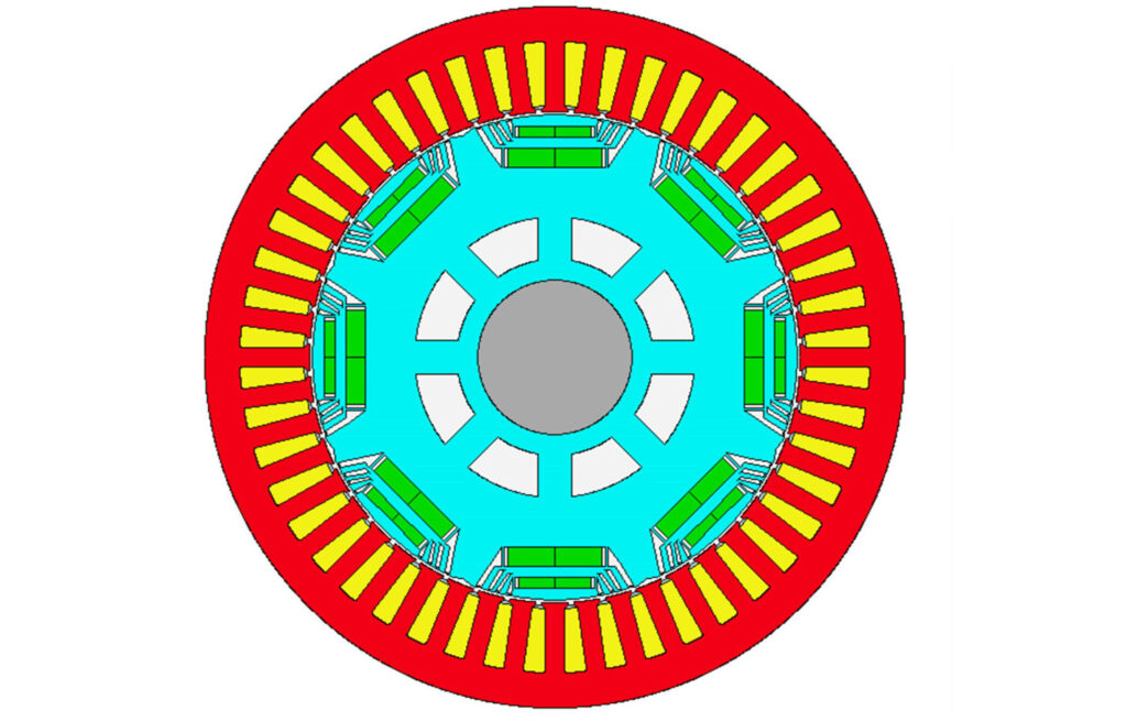
(Courtesy of MotorCAD)
Hybrid motors
Many radial flux motors use a hybrid approach with a permanent magnet and using the design of the rotor and stator to increase the reluctance within the motor.
In a reluctance machine the rotor will be made entirely of electric steel. The motor works by exploiting the tendency of the rotor to align with the magnetic pole, which is how it produces torque.
The difference in permeability along the two axes of flux (polar and interpolar) creates the reluctance. This reluctance torque allows the design to minimise the size of the magnet needed to produce a given torque.
The hybrid approach allows the reluctance to be varied by controlling the current through the winding. The reluctance torque is then used to reduce the size and cost of the permanent magnets and get a wide efficiency over the range of speed and torque.
The reluctance torque is generated by current running through other parts of the stator (firing currents into coils at the stator tooth to generate the field). This stator current is offset by 180º from the rotor current to generate a field in the rotor. It means a more complex controller is needed, and the absolute efficiency is not quite as good as a pure IPM design, but the average efficiency across a large proportion of the range – especially in the lower range – is just as good.
That is a key point – the design needs to focus on the efficiency at the desired torque and speed range in which a vehicle will be operating, rather than the average efficiency across the whole range.
For the mainstream automotive sector it’s a popular choice for controlling the rotor’s magnetic field, as it has the benefits of a permanent magnet motor without having to use field weakening. However, that quickly leads to a system that is complex to design and model.
The simulation methodologies for these motors are complex, with many different magnetic and electrical elements, so sophisticated magnetic modelling tools are needed. These motors also need complex controllers that in the past required costly semiconductors, but the latest processors are fast enough to handle the complex mathematics.
Surface permanent magnets
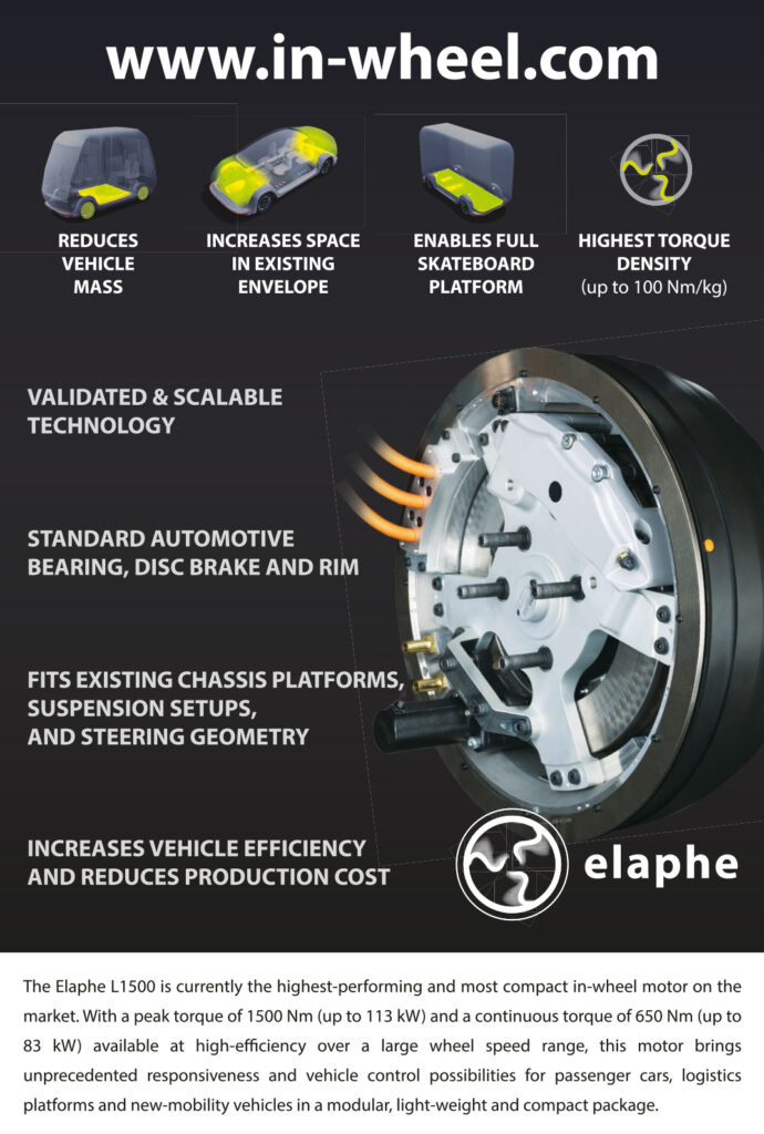
For higher power density and faster motors above 20,000 rpm, SPMs are becoming increasingly popular. They can provide peak torque for longer, for example for 30 s rather than 10 s, in a hybrid IPM motor. Beyond 20,000 rpm though the gearbox design is much more complex.
The downside of an SPM motor is that it has more permanent magnets than an IPM motor. It is also 10-15% more expensive than an IPM but twice as power-dense, making it suitable for premium, high-performance applications.
With a silicon carbide inverter, the combined cost is much higher than for an IPM, but the inverter/motor efficiency is also much higher. That means the battery pack can be smaller to save money on batteries, or the pack can provide longer range.
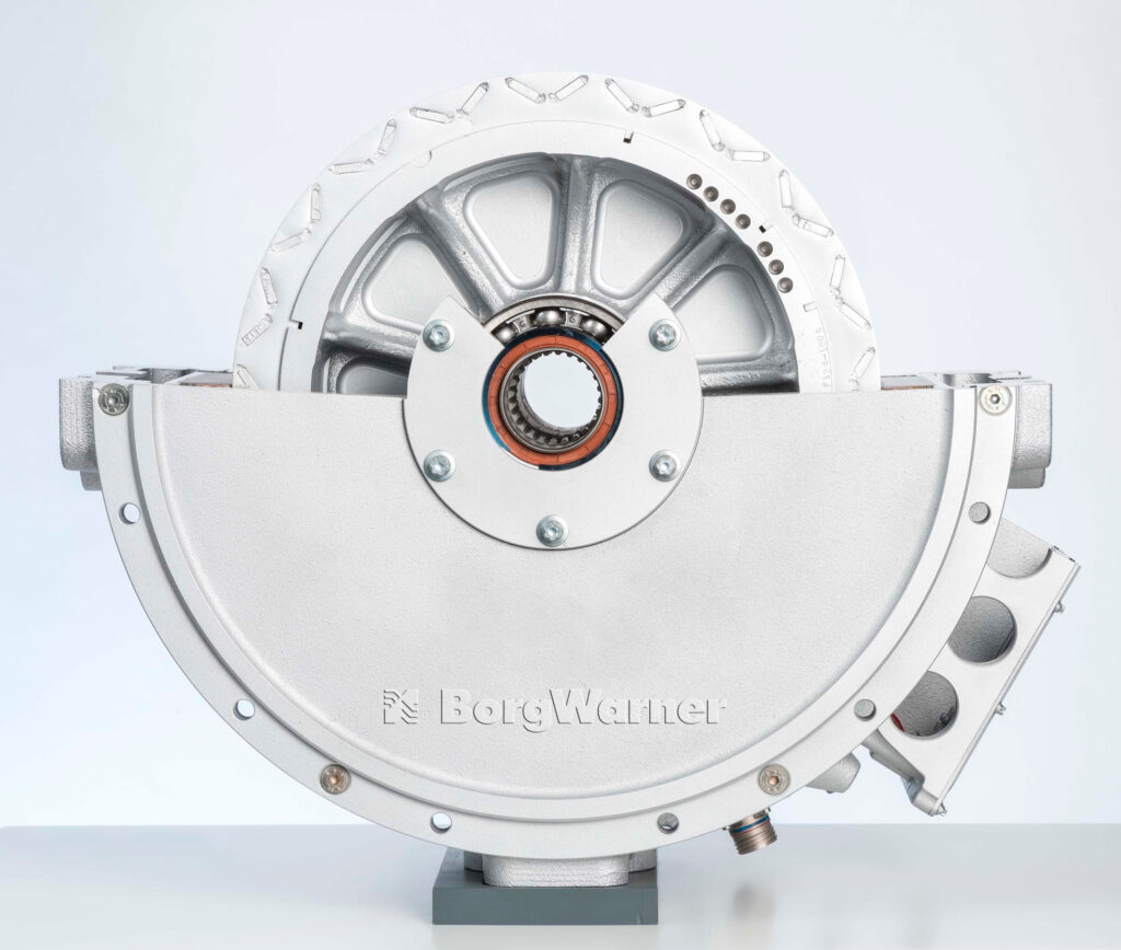
(Courtesy of BorgWarner)
Induction motors
Rather than having an array of magnets and using the shape to concentrate the flux, an IM induces a magnetic field in the motor using copper bars. Some electric car makers use a hybrid design that combines a reluctance field and a permanent magnetic field. This is being used in motors that are running at up to 18,000 rpm and are now becoming mainstream.
The rotors can also get hot from the induced field, so an induction motor may need more cooling, which can limit the maximum power the motor produces.
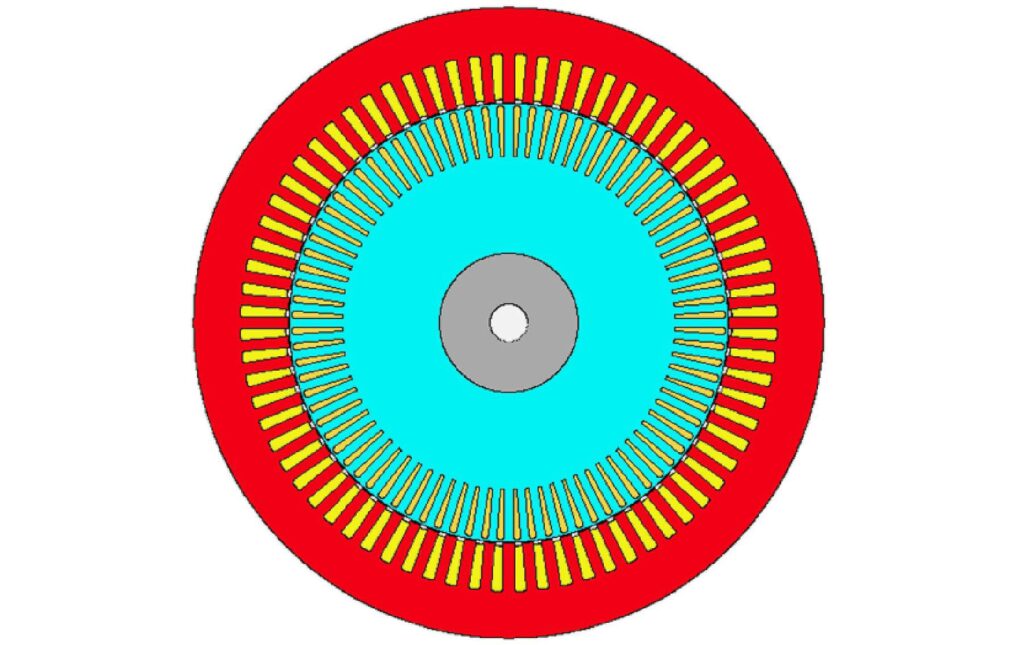
A typical 150 kW, 350 Nm IM design has 72 stator slots and 84 rotor bars. It is a six-pole rotor with a die-cast copper cage. The laminations use M250-35A grade electrical steel. The rotor bars have a 5º mechanical skew applied to minimise torque ripple.
This IM design uses a single-layer winding with a 40% slot fill factor and three turns per coil with 15 strands in hand per turn. Two parallel paths are used per phase.
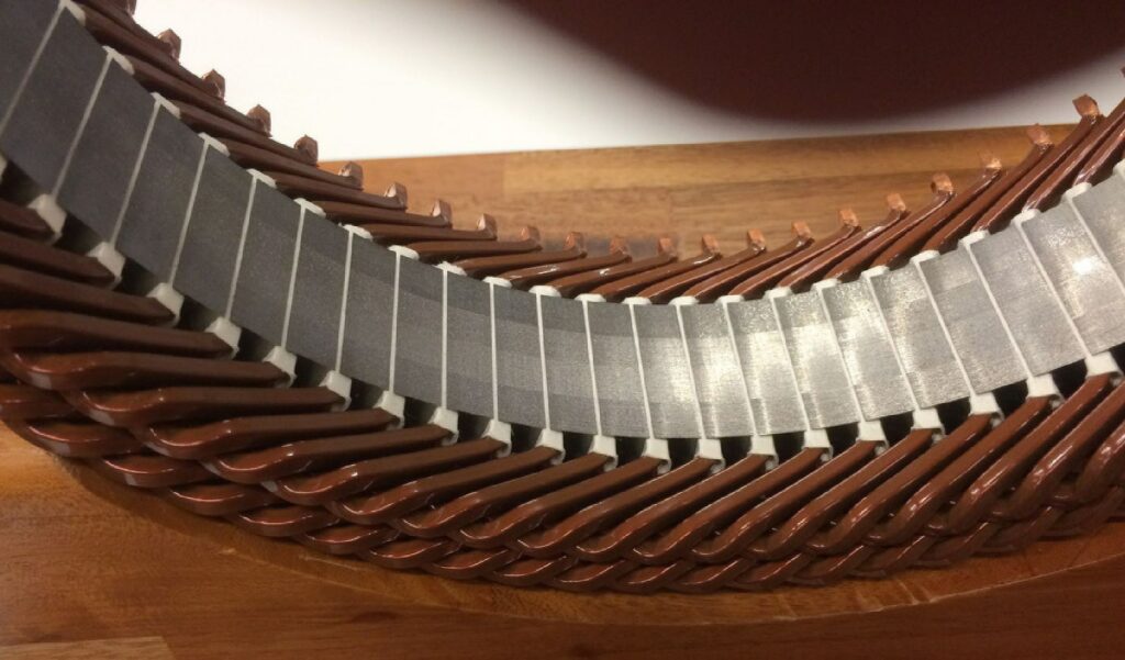
Hairpin windings are becoming popular for high-volume electric motors
(Courtesy of MotorCAD)
The WFSM design
A wound field synchronous machine design is a variant of an IM. A 150 kW WFSM motor uses a 48-slot stator and an eight-pole rotor, with the laminations using the same grade of electrical steel as the PM and IM designs.
In a WFSM motor, the field from the rotor is created by the concentrated windings around each tooth. Direct current is applied to the windings through slip rings, which allows the excitation in the rotor to be controlled. The rotor winding has 132 turns, and up to 16 A of DC is applied to the windings.
The WFSM can use a combination of alignment and reluctance torque, as with a PM machine.
The winding uses the same pattern as the PM machine above, with six turns per coil and 15 strands of copper per turn. Again, a 40% copper slot fill factor is used.
An IM has a slightly lower peak efficiency, of 95.5%, than permanent magnet or WFSM motors; peak efficiency occurs at higher speeds, from 7000-12,000 rpm. At lower speeds, for example at 50 Nm and 2000 rpm, the IPM and SPM motors are 4% more efficient than the IM.
At higher speeds and lower torques, however, the opposite is true and an IM has higher efficiency than a PM machine. This is due to the iron losses generated in the PM machine, even at no load, as well as the field-weakening current required in the PM machine at higher speeds to suppress induced EMF from the rotor excitation to stay within the maximum DC link voltage.
A WFSM has a similar peak efficiency to an IM. The maximum efficiency region occurs from 5000-10,000 rpm and at higher torque levels than a PM or IM machine.
Stator temperature
This focus on a short peak performance in automotive designs allows the current through the stator, and so the temperature, to be higher, providing higher peak power.
In the past, the allowable stator temperature was up to 180 C to allow for hotspots, but now motor designers are allowing that to reach 220 C by using better insulation and encapsulation materials. While hotspots can still occur, the impact is less significant, as a vehicle might be designed to last 10 years rather than 20 years of continual use for an industrial motor.
Some of that comes from the design of the stator and the winding, such as concentrated, segmented or hairpin windings. These have different ways of removing the heat.
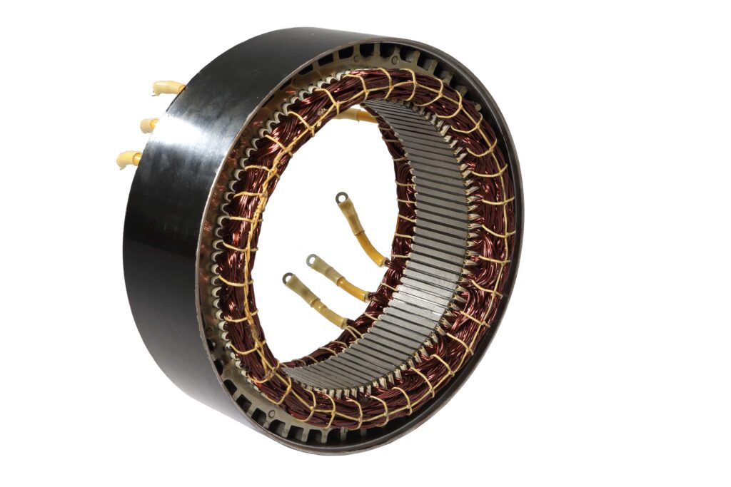
Stator steel
A stator is often constructed from a stack of steel laminations – thin sheets of steel shaped with teeth so that copper wire can be wrapped around it to form an electromagnet. Here the quality of the steel is key. It has to be very good for the magnetic flux, with no inclusions that induce losses, and needs tightly controlled grain of consistent quality.
The grain-oriented steel, where the grains are aligned and so support a higher flux, is more expensive than non-grain oriented. This is key, as the thinner the steel the better, since the magnetic field travels on the surface. However this thinness makes the stator steel harder to handle in manufacturing.

The optimum thickness is 0.15 mm for a high-performance stator or 0.5- 0.6 mm for a mainstream design, as it is the mechanical issues that are the problem. Welding and interlocking can damage the sheets, reducing the field and the motor’s performance, and there is still significant technical development of ways to hold the sheets together, using a single-ring or segmented design.
The sheets also have a layer of insulation a few microns thick that can be adhesive or used with a mechanical interlock.
Laminated stacks of specialist steel are not the only way to make the stator teeth though. For lower power applications such as e-bikes, pressed steel powder can also be used.
The stator design is a crucial element of the motor design. While the geometry stays the same, different stator lengths and materials can lead to different form factors.
(Courtesy of Avid)
Windings
There are 10 or so different winding techniques, from a continuous hairpin and needle winding to a slotted winding, or lit wire.
A concentrated winding is the traditional approach, where windings having one slot per pole per phase. The coils of fractional-slot concentrated windings are concentrated around the teeth, so do not overlap.
A segmented stator winding is used if lots of winding is needed in the stator design to achieve the required power and torque requirements. However, the design of the segmented stator coils has negative repercussions on the material and production costs. Often, complex processes are needed to form the single teeth to a round stator, and the large number of contact points can also be a challenge for manufacturing.
These segmented windings can come in different shapes, such as teeth or wings; the number of segments maps to the number of poles. The design of the segments can be carefully modelled to maximise the performance of the motor by increasing the flux generated.
This is a complex balance of the fill factor of the segment – that is, the amount of wiring in the space – and the shape and permeability of the wiring. The design of the windings is more important in hybrid, IM and WFSM designs, which rely more on the electrical elements of the motor, than the IPM and SPM motors with permanent magnets.
The IPM design example above has a distributed winding where each turn is made up of multiple strands of small round wires. A single-layer winding is adopted, which means that each slot is occupied by a single coil and phase.
The coil pitch is five slots, and there are six turns per coil each with 15 strands per turn. The slot fill factor, which is the ratio of copper to slot area, is 40%. The winding uses two parallel paths per phase.
The quality of supply of the copper for the wires is vital, as any variability in the material can have a major impact on the performance.
While aluminium is often considered as a replacement for copper – it being lighter and cheaper than copper – aluminium wires also get hotter, are harder to handle and have cracking issues. It is therefore used more for busbars than windings.
A different approach is to use a bar, or hairpin, winding. In this approach, a thick copper bar in a ‘U’ shape is inserted into the stator. This is a machine-intensive process though, so it’s no good for small production volumes.
But hairpin windings have distinctly different manufacturing and assembly processes in comparison to traditional stranded windings. This may have manufacturing cost benefits, and the repeatability is much better because the position and placement of each conductor is well-known and controlled.
In addition, the end windings are typically more compact in hairpinwound machines. However, the rectangular conductors also have some drawbacks, such as significant AC winding losses.
Hairpin windings have good efficiencies at lower speeds and as manufacturing techniques and rotor profiles improve, problems with AC eddy current loss can be addressed. They also have bigger losses at higher frequencies and speeds than concentrated windings, but they are suitable for a single size of motor in a mass-produced passenger vehicle.
However, there is plenty of innovation in the different types of copper windings used for rotors in radial flux motors. Some types of copper wire are essentially hexagonal in crosssection, and that gives better packingand avoids the losses associated with a hairpin design. This is suitable for lower speed hybrid motors running at 3000-4000 rpm, but losses appear at higher speeds from surface effects as eddy currents in the surface in the wire create additional heat that has to be removed.
Cooling
Cooling is a critical factor in the performance of any of these motors. The challenge is to get the heat out of the wire on the stator, which exhibits ohmic heating (I2R), with the magnetic field also inducing heat in the stator and the rotor.
This can be achieved to an extent with an external cooling jacket around the motor that uses a mixture of water and glycol to carry the heat away.
The problem though is that the wire bundle is not on the cooling jacket, so designers look at creating a better thermal pathway to the cooling jacket. This can be by spraying a dielectric non-conducting oil – transmission fluid – onto wire instead of onto the jacket.
With this approach, the oil is applied directly to the end windings of the machine to remove heat. The oil is removed from the machine through a sump and recirculated through the vehicle’s cooling system.
There are generally two ways of applying the oil to the end windings. One is to pass it through a hollow shaft and use the centrifugal forces during rotation to throw it onto the end windings.
Another is to apply the oil directly to the stator end windings through nozzles, often through an oil distribution bar over the upper surface of the end winding. These operate with a typical flow rate of 4 litres/minute for the shaft oil and 8 litres/minute for the stator oil.
Both methods can have drawbacks though. Throwing oil off the rotor means that at zero or low speeds the end windings are subjected to asymmetric oil cooling due to gravity. That leads to relatively higher temperatures at the upper part of stator end windings as the copper loss component is substantial at stall and low-speed operations.
Applying the oil to the end windings directly from the oil distribution bar can give a very uneven distribution of cooling around the radial periphery. Both these cooling methods can lead to an additional windage loss owing to the intrusion of oil into the rotor-stator gap.
However, both methods can be combined. Oil is passed through the shaft and thrown onto the end windings. In addition, a set of axial channels is used to pass oil along the axial direction, with nozzles at both ends of the channel to distribute oil over the end windings. This also has the advantage of cooling the active section of the machine in a similar manner to an axial water jacket.
In comparison to water cooling, the use of oil cooling has potential cost benefits, as the oil cooling system can be shared with the transmission. The cooling is quite effective thanks to a high rate of heat transfer between the end windings and the coolant oil.
That though increases the complexity of the cooling system significantly as it needs a pump to move the oil out of the motor through a pipe with a seal. That can increase the cost of manufacture and reduce reliability. The oil carries less heat than a water-glycol coolant, so it needs a larger heat transfer element.
With a water cooling jacket, the water provides twice the specific heat of oil but can’t directly cool the windings, so designers have to optimise the cooling paths to the jacket. That means encapsulating the winding with a material with good thermal conductivity, but getting encapsulant to flow effectively over the winding is difficult.
This cooling architecture relies on turbulent flow in the cooling jacket, and the jacket has to be a shape that can be manufactured cost-effectively. However, it benefits from the same engineering as an internal combustion engine, with a low-cost pump and radiator.
Another alternative is to cool the rotor with a tube running through the motor axle. This suffers from the same sealing issues though.
The water jacket is the simplest approach and provides reasonably good cooling. Adding internal circulating air adds components, such as a fan, but it might enable the use of lower-grade magnets owing to reduced rotor temperatures, and result in an overall cost saving.
When compared to electrical losses, the windage loss caused by the fan is relatively small because of the low density of air, but that should have a minimal impact on the motor’s efficiency. The oil cooling adds quite a lot of complexity to the design but also gives effective cooling and potentially simplifies the vehicle cooling system.
Overall, the choice of cooling system depends on the required thermal performance, the cost trade-off between components and the vehicle’s cooling system design.
All of this comes together for the design of motors for the aerospace sector.
The design principles are the same, though of course with more focus on the power density by using lighter cooling systems, and less on torque variation. While cost is a less important factor, reliability is key.

For aerospace applications, radial flux motors have been developed with a power density of 40 kW/ kg using a coolant at 20-40 C. It can reach 45-50 kW/kg with further optimisation.
The dominance of radial flux motors for e-mobility has not restricted innovation in their design and development. Refinements across the whole motor boost performance, but they have to be matched with effective cooling technologies to ensure the internal temperature remains low. These designs are also looking at cost engineering, to reduce the amount of permanent magnet used with innovative stator and winding designs.
Acknowledgements
The author would like to thank Ryan Maughan of Avid Technology, James Goss of Motor Design and consultant Jason King for their help with researching this article.
ONLINE PARTNERS


