


")


")
eAxles
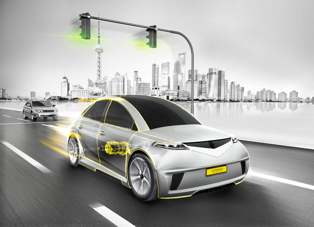
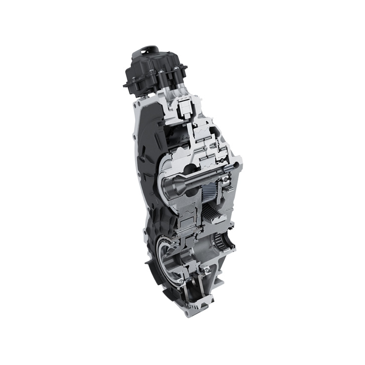
(Courtesy of Vitesco Technology)
Peter Donaldson canvasses some Tier 1 suppliers’ views on contemporary eAxle technology and the likely future trends in their design.
Driven by the OEMs
Integrating a motor, gearing and power electronics into a compact, modular package that sits between a vehicle’s driven wheels creates a system that has come to be known as an eAxle. It is an increasingly attractive option for manufacturers of passenger cars, small commercial vehicles and trucks who want to develop hybrid and all-wheel-drive versions of existing products, while for developers of pure EVs they are a means of making the best use of the internal volume for extra battery capacity, passenger space or other selling points.
The eAxles themselves are increasingly closely integrated for compactness and the packaging flexibility that comes from that. This raises challenges though, such as cooling and access for maintenance and repair, in addition to the choice of motor and inverter technologies, gearing and differential options and their impact on suspension design.
A developing market
The market for eAxles in passenger cars and light commercial vehicles is growing and maturing rapidly, with one supplier reporting a large increase in enquiries over the past two or three years.
However, it is still early days, suppliers say, even more so for the market in heavier commercial vehicles and offhighway machines. These vehicles are less constrained in terms of space, and tend to provide more options to place the electrical machine (EM) in different positions in the driveline.
The terminology for these positions has developed to describe hybrids, some of which don’t allow the EM to be decoupled from the engine.
In P0, the EM is connected to the ICE using a belt. In P1 it is directly connected to the crankshaft. In P2 it is decoupled from the engine but is geared to or coaxial with the transmission input between the ICE and the transmission, and turns at engine speed or some multiple of it.
In P3, the EM is geared to the transmission output and turns at a multiple of wheel speed. Finally, in P4, the EM is a standalone axle decoupled from the engine, often at the rear.
The eAxles that are the subject of this article are generally at the rear in ‘addon’ hybrids based on front-wheel-drive platforms and in pure EVs, although the latter also have the option of the frontaxle position and must therefore also accommodate steering.
Vehicle OEMs are in the process of deciding whether to outsource the complete axle, certain components or to make the complete unit in-house. This situation forces Tier 1 suppliers to prepare for all of those possibilities with products that can meet OEMs’ needs and be brought to market quickly.
That is a challenge because of the wide variety of market requirements and the resulting powertrain complexity. One supplier comments that because the development of three-in-one (EM, gearing and power electronics) products is a huge effort, they need to create modular families with guaranteed applications.
While the EM technology is fairly mature, at least for most of the permanent magnet motor options now being considered, another supplier notes that the main development effort is in integrating all of the eAxle’s subsystems into ever-tighter packages to enable them to fit into more application spaces.
Anticipating larger production volumes for battery-electric vehicles (BEVs), another supplier judges that eAxles rated between 60 kW and 200-250 kW will be sufficient for most applications in light-duty vehicles such as cars and SUVs.
However, they note, OEMs are taking different approaches, with some focused on electrifying affordable vehicles while others such as Porsche and Tesla want very high performance, so there is no single powertrain architecture that could be called the main trend.
This has led to the conclusion that they must develop and offer a ‘kit’ from which OEMs can choose the kind of e-drive system that best suits their application while allowing the supplier to make the most of what is expensive development work.
Technical requirements for commercial vehicles are quite different. Even the smaller parcel delivery trucks, for example with gross vehicle weights of 2.8-3.5 t, have a significant impact on the gearbox. Driving profiles are also very different, being characterised by shorter distances and many starts and stops.
As yet, there is no established market for electrified trailer axles for articulated lorries, but one trailer supplier we approached does see one developing – particularly for refrigerated trailers, known as ‘reefers’.
Market drivers
eAxles for these vehicle categories are also affected by similar top-level market drivers of cost, flexibility and durability, although they are subjected to very different duty cycles, and the technology levels deployed to achieve them can cover a very broad span.
For light-duty vehicles, the emphasis is on cost, packaging space, energy efficiency, low or zero emissions and performance with noise, vibration and harshness (NVH) close behind. One supplier says cost is the top priority, because the e-drive system is not seen as something that customers use as a discriminator between cars – as, for example, engines are.
Efficiency comes next because an EV’s most important and expensive single component is its battery, and even a 1% efficiency gain in the powertrain can save a lot more in this area.
For commercial vehicles, the emphasis is on total cost of ownership and cost of operation, making energy efficiency and maintenance requirements particularly important. In buses operating in noiseregulated areas, NVH is also important.
For commercial vehicles in particular, upcoming zero-emissions zones in cities and more broadly applicable new regulations further limiting noise and CO2 output are influencing development, boosted by government incentives for zero- and low-emissions vehicles (ZEVs) and freedom from restrictions for electrified light duty vehicles.
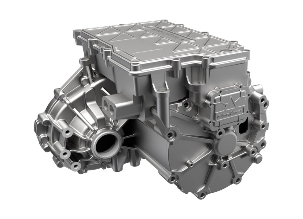
(Courtesy of BorgWarner)
In cars as well as light commercial vehicles, the flexibility stemming from the eAxle’s applicability to hybridising existing platforms and pure EVs is also regarded as a market driver.
The picture in off-highway applications is very similar to that in the commercial vehicle sector. One supplier emphasises that in many cases, such as mines and cargo-handling facilities, ZEVs are essential for safety.
Architecture and evolution
The architecture and layout of eAxles is completely different from that of traditional axles. For more than a century, driveline suppliers have been transferring power from the front of the vehicle out to the wheels, in most cases turning the power through 90º. In an eAxle, the EM can be laid out parallel to the rotational axis of the final drive.
That has a major effect on the gearing, in that parallel shaft gears have replaced hypoid gears. It means the axle can be packaged more like a transmission, with the gearing primarily there to multiply torque and enable delivery of more power.
There may also be multiple speeds and a gearshift mechanism within the axle to allow more efficient use of the motor in pulling away, at low speeds and at high speeds. While multi-speed gearing might take up more space in the axle, it also enables the use of highspeed motors, which are more compact and power-dense than lower-speed EMs.
However, one expert points out, recent advances in gearing and oil systems have enabled larger reduction ratios in single-speed transmissions, enabling the use of electrical machines that run at higher speeds and therefore achieving higher power densities.
Packaging limitations primarily affect the torque the motor can deliver, as the effect on power can be compensated for to some extent by increasing the rpm up to which the motor delivers its maximum torque. The caveat here is that the resulting axle might only provide its maximum power at very high speeds, which is probably not what the OEM wants for the vehicle.
It is important to distinguish here between transient peak power, which is rarely used for more than a minute, and continuous power. It is much harder to design a cooling system that will extract enough heat to sustain the desired continuous power as packaging constraints get tighter, because the surface area available for cooling tends to shrink.
Heat problems can be alleviated with the right inverter technology, with particular attention paid to the number of switches in the package. The inverter is normally the limiting factor here, as motors typically have a much greater thermal mass.
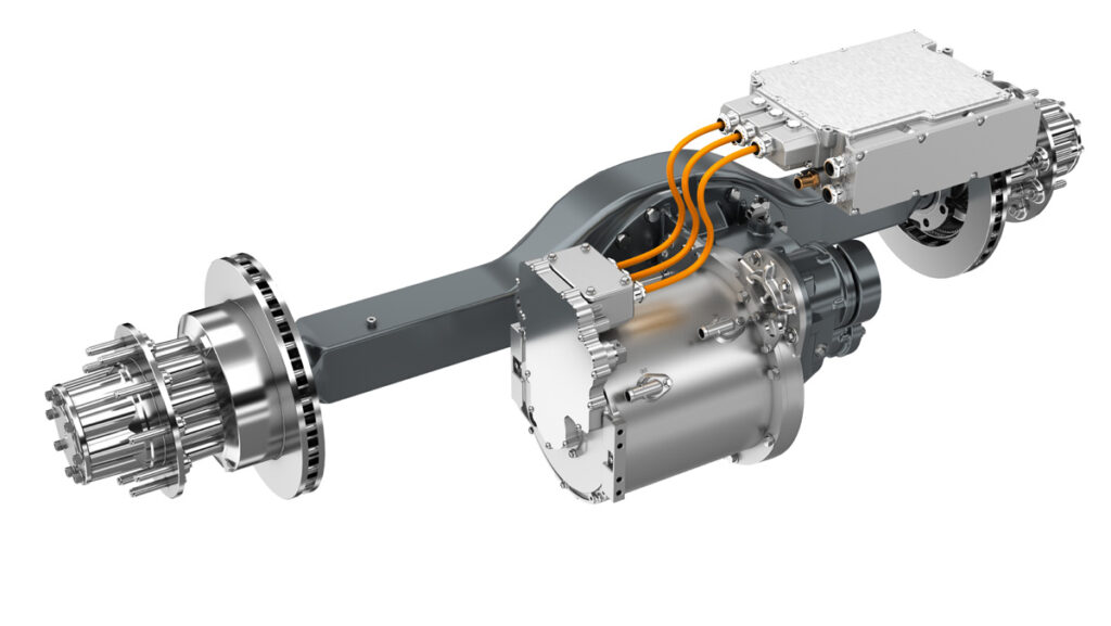
Heavier trucks, in classes 7 and 8 for example, can be difficult as regards packaging because many of them have air suspension, and the airbags take up a lot of room behind the axle. If it is not possible to fit a sufficiently powerful eAxle between the airbags; another solution has to be found that puts the motor in another location, in an e-transmission for example.
Pressures of time
The main challenges in developing eAxles are not ones of fundamental technology but of managing cost and time pressures, and bringing different engineering disciplines together properly. Achieving economies of scale to amortise the costs of developing specific eAxle components is more of a challenge than the technical aspects of greater integration of components, one supplier says.
However, such integration requires people with different areas of engineering expertise to work closely together. That includes mechanical engineers for the transmission and overall mechanical integration, electrical and electronics engineers for the EM and the power electronics, and software engineers for the control functionality.
The speed of change is a particular challenge, a Tier 1 supplier says, as OEMs are looking for solutions that can fit their vehicles now, and they don’t have the flexibility to redesign the entire chassis and suspension layout.
With a few exceptions such as Tesla and even more niche car makers, OEMs are still a few years away from clean-sheet designs for EVs, because the market is still too new, so they want eAxle solutions that are compatible with their existing petrol and diesel platforms. That not only makes physical packaging difficult, it also presents thermal management problems because of restricted airflow, meaning suppliers have to develop elaborate cooling systems.
As more vehicles are designed from the start to run on electric power alone, however, these issues will become much easier to handle because their unibody architecture will be different. With no need for a transmission tunnel, for example, the floor can be flat and most of the underfloor area can be dedicated to the battery, as is the case with Teslas and other purpose-designed pure BEVs now.
What’s more, not only will the suspension and steering geometry be optimised for vehicles with inherently lower centres of gravity, it will also be designed to accommodate eAxles with fewer restrictions on their size, shape and the airflow around them.
(Courtesy of Dana Incorporated)
All the experts consulted in connection with this article agree that, overall, the element of the electrical system that has most effect on the vehicle to which it is added to create a hybrid is not the eAxle but the battery, whose weight means that suspension, braking, sprung mass, anti-vibration mounts and structural resonance effects all have to be reviewed.
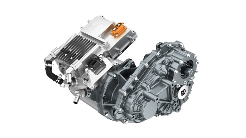
Trends in larger vehicles
While bigger vehicles generally provide a little more space, they need a lot more power and therefore larger motors and inverters.
This is commonly encountered in large commercial vehicles, where most OEMs globally are looking at direct drive solutions, in which they are simply replacing the engine and transmission with an electric motor, which packages fairly well in those vehicle types. If you can mount a large traction motor centrally – and even a gearbox, if required for power – then the rest of the chassis remains largely the same, one supplier says.
There are some that are coming to the market with eAxles, and there are a few already out there but not yet at scale. If you look at any EV in the commercial vehicle market right now, globally about 95% of them are direct drive.
Some suppliers view hub motors in the same vein as eAxles, because an axle is the mechanism between the wheels that provides them with power and the hubs are positioned on that line.
(Courtesy of Dana Incorporated)
Hub motors are starting to make headway in the off-highway market, as vehicle OEMs are used to providing the packaging space required for geared hubs for mechanical drives. Combining a planetary gearset and a motor in the hub can deliver a lot of power, and one supplier anticipates a lot of interest in that kind of solution.
Hub motors have been the subject of development work for applications in the light and commercial vehicle markets for around 30 years, the supplier notes, adding that there are still challenges to be overcome before they are likely to see widespread use in these sectors.
Not only does putting a motor and gearing with the wheel hub increase unsprung mass, it also subjects them to all the suspension movement and shockloadings on rough roads. That makes it difficult to ensure that the rotor and stator in the motor do not come into contact.
Tier 1 suppliers generally want to cooperate with as many automotive OEMs as possible while avoiding the extra cost and effort involved in developing many bespoke solutions. That means they have to define the packaging space at the beginning so that they know what the dimensional limits are, along with the mass and required performance of the vehicle.
To avoid over-engineering, they calculate the power needed to accelerate the vehicle from zero to 100 kph in 8 or 10 s, for example, then work out what that means for the eAxles. Through discussions with OEMs and constant monitoring of many data sources they learn what the targets for cost and efficiency are.
With these parameters determined, they can then begin developing a generic technology platform that can be implemented in different power classes.
Hybrids and EVs
Developing eAxles for hybrids and pure EVs require similar approaches, but there are some important differences. While both need electrical machines, power electronics and transmission components, they typically have different duty cycle requirements. Hybrid transmissions are inevitably more complex and present cooling and sealing challenges, and more attention has to be paid to torsional vibration and clutch loads.
An eAxle for an EV has to cover all of the vehicle’s propulsion requirements, but one for a hybrid has to operate in conjunction with the ICE, so the axles have to be specified and optimised differently. Basically, in vehicles of similar size and performance, there are likely to be differences in the size and power of the axle’s electrical components. For example, an eAxle for a hybrid might not be designed for maximum speed, for which the vehicle relies on the ICE, so it is likely to have smaller components.
The pursuit of fuel efficiency with decent performance in a hybrid means the eAxle must be engaged and disengaged at different times. It might for example be used on its own at low speeds in stop-start traffic or in conjunction with the ICE for extra acceleration, and be disengaged at high speed.
This last case improves overall efficiency by eliminating the drag of an axle that is not providing power at high speed, and protects against wear and tear and potential damage to the motor and gearing if they are not designed to run at such speeds. Naturally, engagement and disengagement require a physical mechanism and control software.
One supplier notes that some eAxle designs can be used interchangeably as the sole means of propulsion in a pure EV and as part of a hybrid system, with the software alone defining the differences between them.
However, there is a key difference between hybrid and pure EVs that can have a profound effect on the design of the e-drive system, and that is the shape of the physical envelope into wich it must fit.
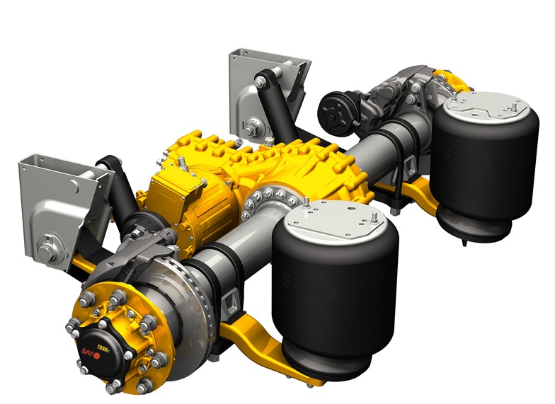
(Courtesy of SAF-Holland)
A typical plug-in hybrid EV, for example, uses the ICE powertrain to drive the front wheels and an eAxle at the rear, but the chassis is likely to be one originally designed for an ICE vehicle. Indeed, most hybrids are parts of a model range that include petrol and diesel vehicles, with suspension, fuel tank and exhaust components in the rear underbody area. That generally means the available space is long and thin.
In purpose-designed BEVs, there is more space for the e-drive system, as there’s no exhaust or fuel tank and the battery’s position now seems to have been standardised under the floor in the middle. That means the eAxle can be made larger in diameter, which has significant cost benefits, as well as being shorter.
Light duty versus commercial
The amount of expected use is another key factor affecting eAxle design. Light-duty vehicles such as cars and SUVs are used much less than commercial vehicles, so their axles have to be designed for longer service lives. Light-duty vehicles also normally operate at relatively low power, with peak power used only during acceleration and regenerative braking, while commercial vehicles tend to need higher continuous power to meet highway gradeability.
This difference in duty cycles tends to shape the cooling systems, with the former tending to use a mix of water and glycol and the latter using oil cooling to improve their continuous performance, although air-cooling remains an option when duty cycle and/or packaging constraints are less severe.
Torque and power differences are also important, and stem from the speed ranges in which the EMs work.
Most motors used in light-duty vehicle applications run at between 10,000 and 18,000 rpm, and have to be geared down substantially to get the final drive to deliver the required power and torque in the right speed range. In commercial vehicles, the motors are physically larger and put out a lot more torque but at lower speeds, peaking at 4000 rpm or so, a combination that results in a lot more power but restricts vehicle speed.
Gross vehicle weight has perhaps the most significant impact on eAxle design. Commercial vehicles of 2.8 t and above have motors that produce more torque, and because electric motors produce their maximum torque from zero rpm onward, the gearing has to be stronger and tougher since high torque at low rpm is very stressful for mechanical components. While software control of the motors can reduce that impact to some extent, there are situations in which the software cannot react quickly enough, one axle developer points out.
For example, if a road surface is icy in places and the vehicle accelerates, decelerates or brakes with one of a pair of driven wheels on the ice and the other on a surface with grip, almost all the torque would be applied initially to the latter. Within the first millisecond or so, a huge torque spike would affect only one driveshaft before the software control could reduce it.
Such situations can cause cracks in the driveshaft and differential. They can also damage the semiconductors in the power stage of the inverter and in the motor, the developer says.
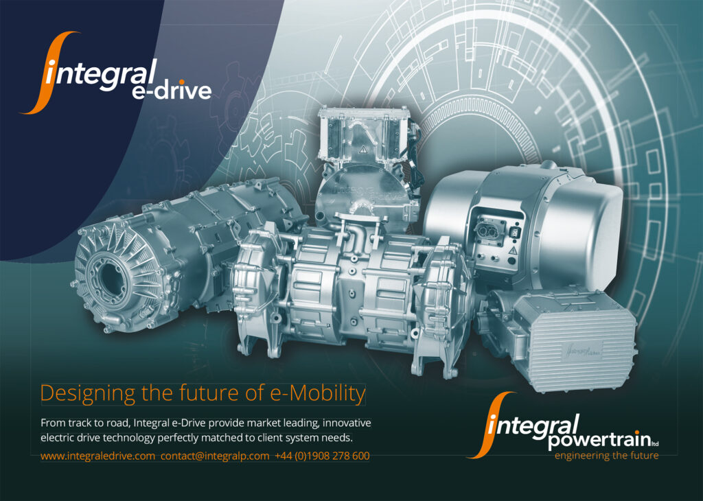
Tighter integration
While there has been no single major technological improvement that has enabled suppliers to integrate eAxles more closely in response to market pressures for tighter packaging and reduced costs, one supplier points to a deep understanding of the principal sub-components – the electric motor, the gearbox and the inverter.
This has led to straightforward but effective packaging strategies, such as eliminating the cable harness and wiring by attaching the inverter to the side of the motor, and to more subtle things such as optimising trade-offs in the relationship between the motor and the inverter, for example.
The magnetic materials in the motor and the semiconductors in the inverter’s power module are very expensive, but by plotting these and other cost drivers on a Pareto chart helps engineers keep costs down while meeting performance goals, perhaps by spending an extra €5 on motor magnets to save €15 in avoiding another power stage in the inverter.
One expert emphasises that key advances in core component technologies include reductions in motor losses via thinner laminations, better lamination and magnetic materials, the use of silicon carbide and gallium nitride for inverters, and materials with higher heat transfer coefficients to enable better thermal management.
The combination of planetary gearsets and a spur gear differential enables higher power densities, another expert says, adding that high-speed electric motors allow reductions in size and weight without reducing performance, but that this is hard on bearings.
(Courtesy of Schaeffler Technologies)
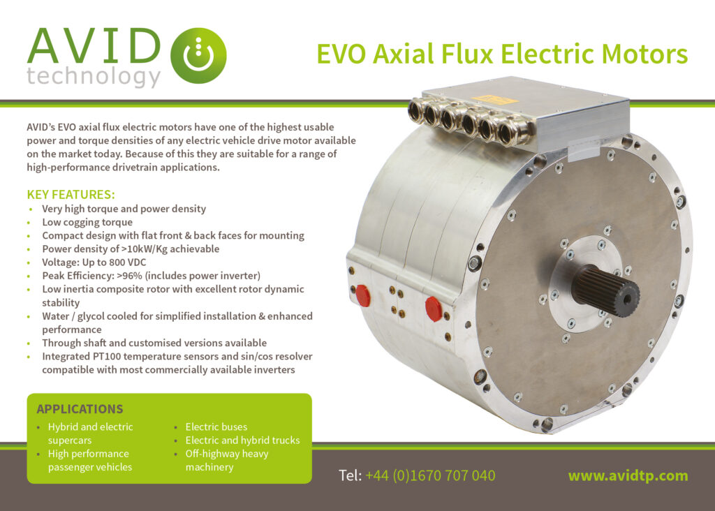
Motor and inverter choices
Most eAxles use radial flux motors because of their low cost compared with axial flux machines, simplicity of manufacturing and ability to operate at higher rotational speeds. While their torque density is lower, the ability to run at higher rpm compensates for that to a degree by allowing the use of higher transmission ratios.
Radial flux motors also tend to be longer and thinner than comparable axial flux machines, which helps with packaging in many volume constrained eAxle applications.
However, an axial flux machine’s high torque and power density, as well as good power-to-weight ratio, makes them particularly attractive for larger commercial vehicles, in which their rotational speed limitations and large diameter relative to radial flux machines do not matter so much.
Motors need precise control from the inverter to set the speed and power they demand and at the voltage determined by the battery pack, whether it be 48, 400, 800 V or more, and while meeting ISO 26262 functional safety requirements.
While many converter/inverter topologies have been suggested as possible candidates for use in this kind of application, two-level, three-phase devices are the most common because of their low component count, maturity and simplicity of control, one expert notes.
One key areas to which suppliers pay most attention is switching, which has a major effect on the overall efficiency of power delivery and is differentiated by the control software and the semiconductor materials used. Insulated gate bipolar transistor (IGBT) inverters are the most commonly used technology in eAxles, but suppliers are closely watching developments in silicon carbide technology.
Achieving the performance, efficiency and cost targets for a new e-drive system requires many engineering tradeoffs. One of the most important of these is the relationship between the magnets in the electrical machine, the size and number of IGBTs in the inverter and the power of the cooling system.
Because IGBTs come in almost standardised ranges that offer much cheaper options than custom made ones, so eAxle suppliers tend to regard them as a given and, to a certain extent, design the rest of the system to make the most of them. This is where it can make sense to spend more on magnets to avoid the need for more IGBT capacity, but thermal side effects put limits on this approach.
As one expert explains, the greater the number and size of the IGBTs in an inverter, the more current it can flow, while the stronger the magnets and the more of them there are in the motor the more torque it can produce.
However, strong magnets induce counter-currents that generate heat within the motor, which requires a more capable thermal management system to remove. On the other hand, reducing the strength of the magnets means more current is required to restore performance, and more therefore has to be invested in the inverter’s IGBTs.
Vehicle control impact
Adding an eAxle to an existing vehicle to create a hybrid can have a major impact on the control software, as the new addition needs a specific control strategy and the system as a whole has to meet Automotive Safety Integrity Level C under the ISO 26262 Functional Safety for Road Vehicles standard. In a hybrid, the eAxle must tailor its torque and power around the ICE drivetrain, which can be a challenge, but in a pure EV the eAxle’s controller simply becomes the vehicle controller, from a propulsion standpoint.
One supplier stresses the importance of understanding the OEM’s safety concept. This is because functional safety can be ensured within the eAxle system, in which case its control software must be smarter than it would be in the alternative approach, in which the vehicle controller takes this role and the eAxle is regarded simply as an actuator that transforms current into torque.
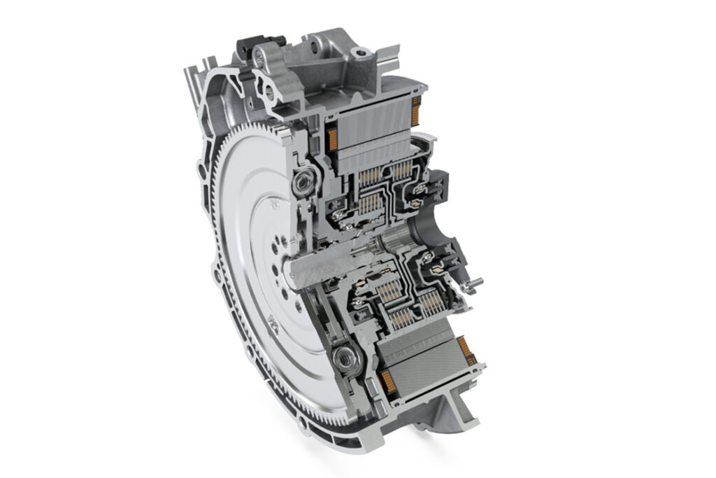
(Courtesy of Schaeffler Technologies)
Future developments
Suppliers agree that even more integration is needed to meet increasingly stringent packaging, efficiency, NVH and cost requirements.
In future therefore, eAxles are likely to have still more hardware and functionality integrated into them, as well as becoming more compact, powerful and power-dense (voltages of 800 V and higher are about to be implemented in high performance applications).
There is still potential to reduce weight and costs though the integration of more electrical and electronic components. Modern vehicles typically have between 30 and 50 control units, and OEMs want to reduce that number.
One supplier suggests that the vehicle controller that sends driving commands to the eAxle could be included in the inverter control board if the latter were given a more powerful microcontroller, as the key component of the vehicle controller is the software. Also, the addition of torque vectoring, the onboard charger, the water pump for the cooling system and even functions such as suspension, steering and energy storage could enable new vehicle architectures and concepts.
As the market demands more eAxles, and production volumes increase, it will make economic sense to make more standardised systems, while at the same time it will no longer be necessary to rely so much on off-the-shelf components as investments in highly customised solutions with related functions combined in adjacent components will pay off.
One supplier expects this to emerge over the next 20 years.
Acknowledgements
The author would like to thank Benjamin Daniel at Schaeffler Technologies, Gabriel Domingues at BorgWarner, Olaf Drewes at SAF-Holland, Ryan Laskey at Dana Incorporated, Simon Mead at Integral Powertrain, Gunter Muhlberg at Vitesco Technologies and Alexander Schey at Allison Transmission for their help with researching this article.
ONLINE PARTNERS


