

")


")


Battery management systems
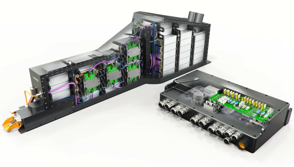
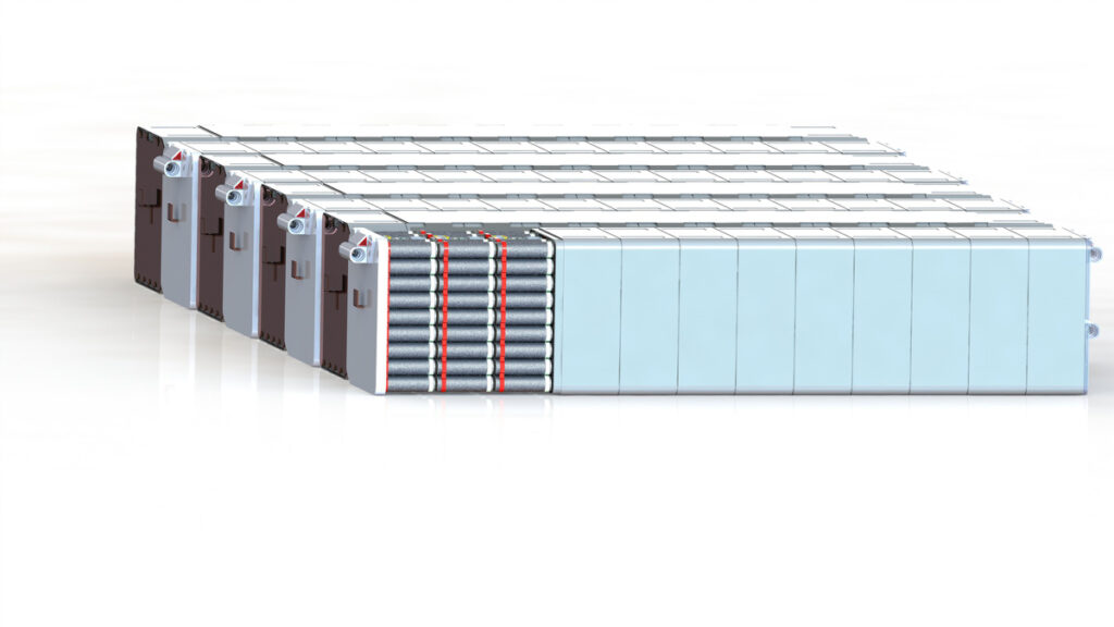
(Image courtesy of Rimac)
Cell calls
BMS technology is still evolving, so EV designers need to know the nuances of incorporating one into an electric powertrain. Nick Flaherty reports.
A battery management system (BMS) is key to the reliable operation of an electric vehicle. The functions it has to handle vary from balancing the voltage of the battery cells in a pack to monitoring temperature and charging rates. That helps to protect the pack from the stresses and strains from overcharging or draining too much current.
Balancing the current drawn from each cell allows the maximum power to be obtained from the pack, providing the maximum range for a vehicle. As the battery cells age, so the balancing and protection becomes even more important to ensure that the vehicle maintains its range over the years.
But getting it right can mean the difference between a reliable, functional system and what has been known as a ‘battery murdering system’ that ends up with battery pack becoming ‘bricked’ and unusable.
Part of that comes from the fact that the monitoring systems and central controllers are customised for each platform using a limited number of technology standards, for example for the comms network that links the sensors to the controller. For electric cars and trucks, the BMS also has to be part of the ISO 26262 safety design process.
The algorithms running on the central controller are also proprietary, and range from simple limit-based approaches to more sophisticated machine learning.
Reliability is a key issue for the BMS. While it monitors the pack, the BMS itself and the monitoring network cannot be a point of failure.

The BMS protects the battery pack from being over-charged (cell voltages going too high) or over-discharged (voltages going too low), thereby extending the life of the pack. It does that by constantly monitoring every cell in the pack and calculating exactly how much current can safely go in as the source charge and come out as the load discharges without damaging it. These calculated current limits are then sent to the source (typically a battery charger) and load (motor controller, power inverter and so on).
It calculates the state of charge (SoC, the amount of energy remaining in the battery) by tracking how much energy goes in and out of the battery pack and by monitoring cell voltages. This ‘fuel gauge’ shows how much power is left in the pack. It also monitors the health and safety of the pack by constantly checking for short-circuits, loose connections, breakdowns in wire insulation, and weak or defective battery cells that need to be replaced.
The BMS also has secondary functions. These include balancing all the cells in the pack by intelligently bleeding off excess energy from cells that have more charge than others. That enables the maximum use, as the pack is only as strong as the weakest cell.
The BMS can also broadcast the SoC to the central controller to provide the ‘fuel gauge’ and the state of health (SoH), the percentage of capacity relative to the beginning of the battery’s life. This SoH can also track changes in impedance in the cells that limit the pack’s performance.
A BMS can also supply data for a safe operating envelope that governs the maximum charge and discharge currents that the pack can support. This allows the traction drive controller to maintain those limits without having to know what’s going on in the battery, simplifying the system design.
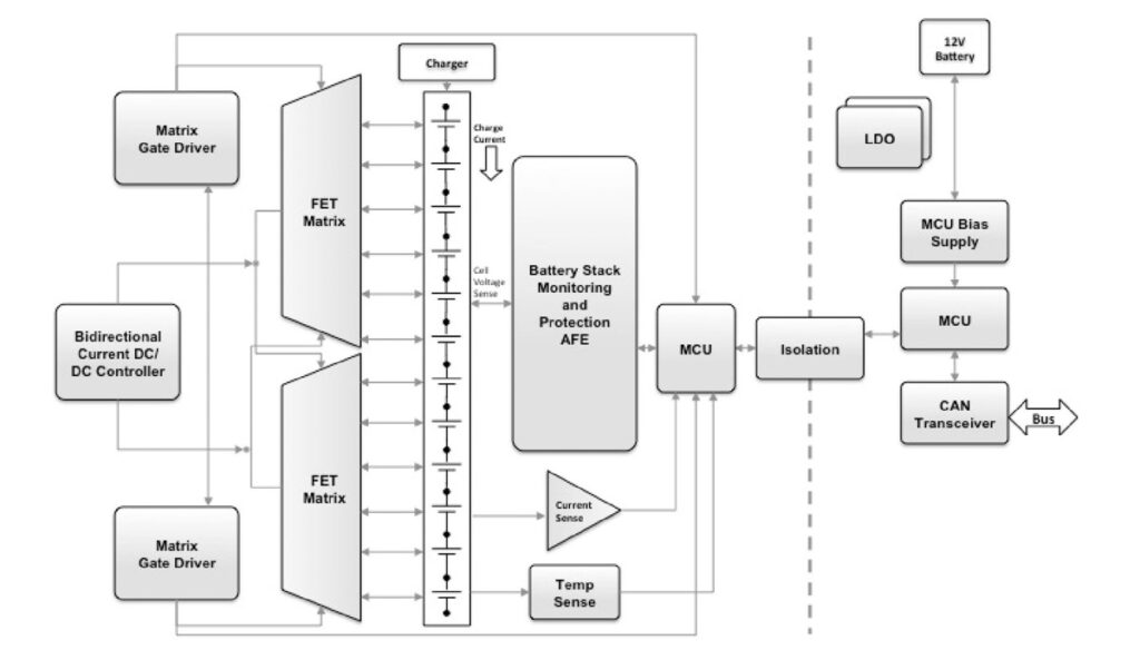
The basics of a BMS are not complicated. A multi-channel cell monitor chip tracks the voltage of a cell, and feeds that data back to a microcontroller running the BMS control algorithm via a network link of some kind.
The devil is in the detail though, from the number of channels in the cell monitor to the choice of networking technology. The understanding of the core physics and chemistry is very nuanced for the design of a BMS over the lifetime of the battery pack, and it can take years to reliably turn that knowledge into effective control algorithms.
The BMS has evolved to its current place in the e-mobility platform because lithium-ion batteries are very sensitive chemical devices that are damaged by overheating or having voltages applied above their maximum voltage range. This requires a precision monitor to manage the risks of overheating and over-charging, as well as to allow the cells to go through multiple charge-discharge cycles. If the cells are stressed then they age faster.
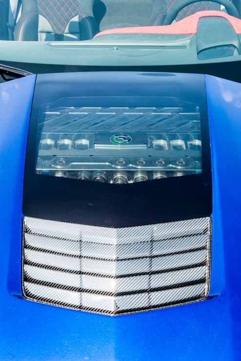
The precision of the monitor depends on the kind of cell being used. However, OEMs want to be independent of the cell types they use so they build more accuracy into the control of the powertrain so they can use cells from different suppliers, and even different technologies for connecting up the cell monitor chips. The differentiation of the algorithms in the BMS has allowed one OEM to develop the world’s fastest electric car, the Genovation GXE, for example.
This is a key element in the BMS, as the various lithium battery technologies have different discharge characteristics. For example, lithium-polymer cells need more accuracy as the discharge curve is flat.
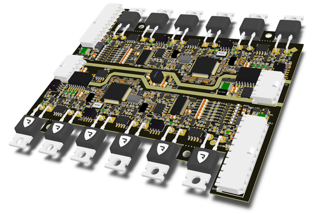
(Courtesy of Stafl Systems)
The demand is for a measurement accuracy of 1 mV, but that comes close to what is physically possible over the age of the cells and the temperature range. The state of the art at the moment is 2-2.2 mV.
Nickel manganese cobalt oxide (NMC) cells have a steeper discharge curve, but the precision in the BMS allows the designer to get closer to the boundary. In the past this required a 10 mV accuracy over temperature and age, but the trend is to go to much lower values.
Another challenge for the BMS is to make sure the battery pack is only used between 20% and 80% of its capacity, as ageing increases above and below these figures. That requires a table of performance parameters, as the capacity also falls with age.
The accuracy of monitoring the voltage of a cell comes from the precision of the analogue-todigital converter (ADC) rather than the conversion speed. In this case the reference voltage is key, as the reference drifts over temperature and the monitor’s lifetime, especially for a standard bandgap reference device.
Having a stable, accurate reference as part of an ADC is non-trivial, and adds significantly to the cost. As there is an ADC with each cell, and 96 cells per pack, this can represent a considerable outlay for a car maker looking to shave costs in every area.
Standalone references may be more precise but have larger packages, and some have to be heated. Instead a particular semiconductor structure called a buried Zener voltage reference can be integrated onto the ADC die, but that requires a specialist highvoltage analogue process.
Because the conversion sample time is less important, a sigma-delta architecture can be used. This uses a single bit that is constantly sampled and the result integrated over time to provide an accuracy of up to 24 bits.
However, there is a limit to the sample time as the current reading needs to be synchronised with the voltage to monitor the cell’s state of health by measuring the inner resistance from this data, so the balance of accuracy with sample time leads to 16 bits being the optimum accuracy.
Measuring the voltage of every cell is essential, as a lithium-ion pack is very sensitive to over-voltage. The number of cells and the design of the pack then has a direct impact on the design of the BMS.
In the past, one module was 12 cells with a local controller with 12 channels. If these were NMC cells with an endof-charge 4.2 V, then this remains below the 60 V safe level (12 x 4.2 = 50.4 V). Now, however, car designers want to fill every space possible in the vehicle, so there are corner modules with different numbers of cells, leading to 12-channel, 15-channel and even 18-channel parts, where each channel has an ADC.
Fitting all the channels into a single part can be a challenge for the chip makers, and then they have to be linked together in a battery pack that might consist of 96 cells.

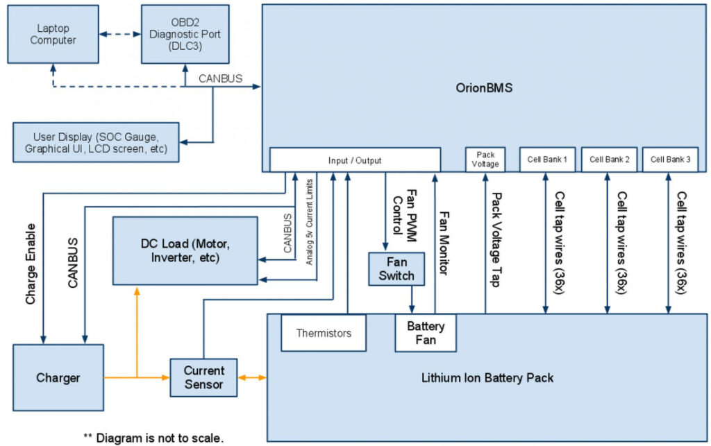
Network configuration
Previous BMS architectures used a star configuration, with isolated CAN bus interfaces to connect every module to the host BMS. Now designers are using a daisy chain with different networking protocols to connect up the monitors.
That has been enabled by bidirectional implementations of serial protocols such as the Serial Peripheral Interface (SPI). The bidirectional capability allows the modules to be connected in a serial chain, passing data from one module to the next.
If there is a break in one part of the chain, the data can be sent the other way around, ensuring reliable operation. The speed of this data link is currently around 1 Mbit/s, which is generally enough to transfer the timestamped current and voltage data.
That gives 290 µs to measure all the cells in 100-cell systems that would generate 400 V in a car design. A truck might have two packs in series for 800 V to provide more power for higher-torque motors.
The holy grail of the ideal battery pack is out there, but it will take 1015 years to reach standard battery pack sizes. The perception is that the industry is still at the beginning of this technology, so there needs to be a lot of flexibility, along with the functional safety and the documentation to prove that failures can be detected at a certain percentage.
Some BMSs such as for the Nissan Leaf use a monolithic central controller, while Tesla uses a distributed architecture. The Leaf modules are configured with four cells in each module – two cells paralleled together and two of these paired together in series (2S2P). That leaves the module with a nominal voltage of 7.4 V and around 66 Ah.
Nissan provides a centre tap on each module to allow the BMS to discretely measure each of the two cells in series. That allows the BMS to be easily used to monitor these types of modules without any modifications to the module itself.
The BMS is also integral to the next generation of charging for electric vehicles. All the DC fast chargers follow a limit from the BMS on the car to get the fastest possible charging. The more accurate that data is, the faster a particular model of vehicle can charge.
(Courtesy of Rimac)
The battery cell business is very difficult for smaller companies to enter, as the capital expenditure is in the billions, so it’s the very large manufacturers such as Panasonic, LG and Samsung that dominate. Theirs show cell failure rates of 1 in 10 million.
When cells come out of the same factory the cell-to-cell batch variation is less than 1%, so the differential ageing effects tend to come from the thermal distribution issues in the pack and the vehicle. For example, in areas of a vehicle with less cooling, the cells wear out sooner compared to cells in the centre of the pack with nominal cooling.
Samsung has been producing the 18650 cell for 20 years and now produce a billion cells a year, so it has optimised the process for high reliability and consistency. The packs themselves however are not at that level of volume, so right now the lower reliability is down to pack construction issues.
The BMS can do a lot but can’t compensate for poor pack construction. The only thing it can do is the cell balancing, but that’s not going to be able to recover lost capacity – if one cell group is hotter then the capacity will only worsen over time.
In most pack constructions the cells are in series with the cells closely matched in terms of voltage. A discharge field effect transistor can be added to drain small amounts of charge to keep the cells balanced, but that usually only happens when the vehicle has stopped.
All the high-volume implementations use that passive balancing strategy. By contrast, an active balancing scheme that allows for charge redistribution to maintain the balance between the cells is popular in theory, but the reliability and uniformity of the cells means it is usually rejected as being too complex, and therefore too expensive.
Standards
(Courtesy of Ewart)
The idea that the BMS is just at the start of the maturing of the technology is driving a lack of standards. Technology suppliers see their offerings as potentially creating an industry de facto standard, especially in the networking between the cell monitors.
There are a number of standards already available for networking, and significant divergence between the technologies. CAN technology is mature and reliable but relatively costly. SPI is a four-wire interface that sends data on each clock edge and is limited to 1 Mbit/s as the 5 MHz clock is at the limit of the electromagnetic compatibility regulations.
Other component makers are using their own proprietary protocols that can run on unshielded twisted-pair cables, which are half the weight of SPI interconnections. One of these protocols uses more of a spread-spectrum approach, moving the point at which the data is triggered in relation to the clock. That makes the signal less vulnerable to electromagnetic interference (EMI) and allows the two-wire operation.
Meeting the functional requirements of ISO 26262 will mean that the BMS must be a failsafe system with redundant resources such as processing units, each of which must have its own dedicated facilities such as memory, multiple ADC converters and others. In addition, the BMS must have self-diagnostics to verify that it is functioning properly and not providing false alarms.
Fast-response protection mechanisms are also essential to a BMS so that, for example, a battery pack or other functional element can shut down immediately should a thermal runaway condition be detected and verified.
To achieve all that, the latest microcontrollers used as the BMS controller that reach the highest level safety specification of ASIL-D compliance use two identical processing cores that mirror each other and execute instructions in lockstep – that is, comparing and validating each processor on every instruction executed at the same time.
Component-level diagnostic techniques, such as error-correction code in memory, help provide accuracy of the data in the system and feed into the larger system-wide selfdiagnostics capabilities. Other designs combine a microcontroller with a digital signal processor core, but the lockstep and validation capabilities have to be developed and verified separately.

Algorithms
Many algorithms have issues with highly variable drive cycles or those without significant rest periods.
Most BMS algorithms are focused on electric vehicles operating for a few hours a day, as cars are used at the moment. But for ride-sharing systems that are used 24/7, or mobile robotics with a duty cycle that is in constant operation with a regular quick charge, there’s a large drift in the Coulomb count, which tracks the flow of current, and that is much more difficult to assess.
The software is the key. The algorithms are much harder to replicate, so providing the full stack of hardware and software is harder to replicate by competitors, say BMS makers. As a result, open source BMS software is regarded as five years behind.
An example of the growing complexity of the algorithms is their ability to learn over time, so that if a cell group is over- or under-performing compared to the nominal values, the BMS can adjust as time goes on.
This technique uses a variant of machine learning and some parameter updates. A state model tracks the state of the battery and determines the error from the actual data. A Kalman filter then adjusts the model to compensate for changes in the future.
The BMS is also becoming important in marine vessels. These have much larger battery packs connected in parallel to drive large motors.
While the safety-critical aspects are not as essential as for electric cars or trucks, there is still the need to shut down packs that fail. This fail capability and managing the parallel packs requires more levels of inter-pack comms and synchronisation.
To avoid monolithic points of failure, that requires a hierarchical system architecture with a master controller to synchronise slave controllers at the system level alongside the powertrain controller.
Future developments
(Courtesy of Ewart)
The cell monitor is not just usable in the battery pack. Kinetic energy recovery systems in electric vehicles capture energy from braking and even from the movement of the suspension.
This energy is usually stored in supercapacitors to boost the motors, but any spare energy is recovered to a separate battery system. Cell monitors are increasingly used in multiple areas, and will be linked to the main battery controller.
That controller is also set to migrate. Instead of feeding data back to a microcontroller on the battery pack, the BMS function is set to be incorporated into the central processor that is also handling the system management.
This more powerful central processor can run more sophisticated machine learning algorithms to further enhance the performance of the battery packs across a vehicle.
Wireless
Connecting up the cell monitors via a wireless network removes the weight of cables. Accurate timing data is achieved with a time stamp to synchronise the data packet, and redundant links can be achieved using a smart mesh architecture that is also used for industrial designs.
A smart mesh uses redundant transceivers to provide alternative paths if there are problems with the network, and gives 99.999% reliability. A prototype of this BMS has been demonstrated, and the final implementation for the same cost as a wired BMS is under development.
That brings additional advantages. If every module in the pack has a wireless connection, the state of the modules being stored in a warehouse can be checked without having to connect them up physically.

The radio transceivers and antennas can also be integrated into the battery pack’s housing, and the housing itself can be built from materials that damp down radio signals that interfere with the network.
Another way around the EMI challenge is to use infrared links. One system that uses infrared interfaces enables data rates of up to gigabit/s for system monitoring with high resolution and fast sampling rates.
Because there are no cables, data transmission is not sensitive to electromagnetic radiation and is robust against mechanical stress. Also, since there is no sensor wiring, short-circuits caused by defective sensor wires are avoided, and the modules and sensors are galvanically isolated from each other.
Transmitting data in this way can be arranged very flexibly, allowing costly work steps such as cable connection, installing cable canals and complex attaching or joining processes to be eliminated.
(Courtesy of Lionsmart)
Solid state
There is a lot of excitement about solid-state lithium-ion cells now under development. The change to solid-state rather than liquid cells does not change the BMS substantially, as it still has to observe over- and under-charge limits, but the changes depend on how the electrolyte is implemented.
The discharge curve for solid-state cells also needs to be shown for longterm performance over at least 1000 cycles. When a BMS maker deploys a pack, they run the cell through an automated test sequence at different rates and temperatures to create a parameter table in the BMS across the discharge curve. At the moment, that is not possible for solid-state cells.
Summary
The BMS is an essential part of an e-mobility system, and the technology is now reaching the ASIL-D safety levels and is being integrated into the ISO 26262 safety design process. Even so, the industry is still at an early stage with the development of the technology, and the refinement of the control algorithms, including machine learning, will continue to evolve.
A range of different technologies for connecting up the cell monitors provide system designers with various options to address the EMI challenges that can reduce the performance of the system. That will take time to settle down to standardised implementations that can drive down costs further.
While many BMS designs are mostly agnostic regarding the mature battery technologies used in packs these days, there is still a lot of work to do on characterising new technologies such as solid-state batteries so that the data can be used to enhance the overall performance of an electric platform.
Acknowledgements
The author would like to thank Uwe Brockelmann at Analog Devices, Erik Stafl at Stafl Systems, Jon Beall at Texas Instruments and Jonpaul Jandu, Tony Allen and Niall Lyne at Renesas Electronics for their help with researching this article.

ONLINE PARTNERS


