


Flexible battery management systems

(Courtesy of ELEO)
Flexible response
BMS developers are offering products that are compatible with the growing range of OEM vehicle models, as Nick Flaherty explains
The trend for battery management systems (BMSs) is to combine elements more flexibly for many different types of vehicles while still maintaining measurements that are as precise and accurate as possible, both at the beginning and over the length of the lifetime of the vehicle platform.
General Motors for example plans to have 30 electric platforms by 2030, which is driving shorter development times, more reuse of components such as the BMS and more use of simulation and modelling in the cloud to shorten test time.
However, the BMS also needs to operate at the highest levels of functional safety – ASIL D – which means having redundancy, and still be as precise as possible with low power.
The cell monitoring chips in a BMS are being designed to squeeze out more measurement capability, capturing data on the current, voltage and temperature in parallel to look at data through the primary or secondary data channels. Previous designs used a multiplexer to handle multiple signal chains for functional safety, but this approach can lose data when using the secondary chain to confirm the data integrity of the primary channel.
Instead, new chips use a more efficient design that keeps all the data but provides multiple ways to filtering the data. The developer can get the raw data as well as the filtered data, and perform a comparison to make sure the data is valid.
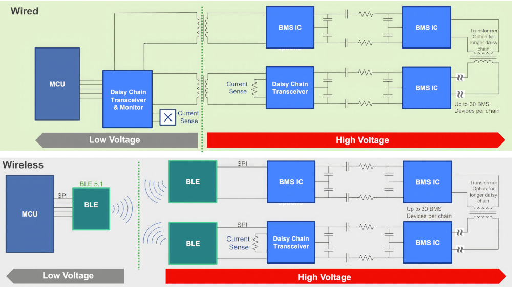
The cell monitoring chips can be used with wired BMSs using an isolated serial peripheral interface or a wireless BMS.
The design of BMS chips is also responding to the needs of the battery pack developers. One system has sensing chips with 10/12/14 and 16 channels that are all pin-for-pin compatible. That means a BMS developer can design a board and go through all the EMI and EMC testing, load tests, hot-plug tests and so on.
The interchangeable chips allow one board layout with a drop-in for the different components depending on the channel count they have. This approach supports a truck, a bus or a range of consumer vehicles.
The monitoring chips are connected via a proprietary daisy chain protocol that can be used with a wired or wireless interconnect, and scales to 400 V to 800 V or 1000 V packs with any combination of battery chemistry with ±5 V on the inputs of each of the devices. The reason for the minus or plus and minus is to handle fuel cells if necessary.
This front-end voltage is determined by a metal interconnect on the chip that makes it easier to create a variant of the chip for different voltages. The analogue front end (AFE) measurement is designed in the silicon, but the gain is programmable in the metal layer. That allows the gain of the chip design to be easily changed to accommodate any input range, for example instead of the ±5 V, it can be zero to 10, zero or -2 to +8 or -2 to +8 or -4 to +6.
But there are other limitations, for example with multiple battery chemistries. One supplier in North America has combined two different battery chemistries in a pack, using LFP for longer range, lower power operation and lithium-ion for immediate power. This can be handled by the same BMS design.
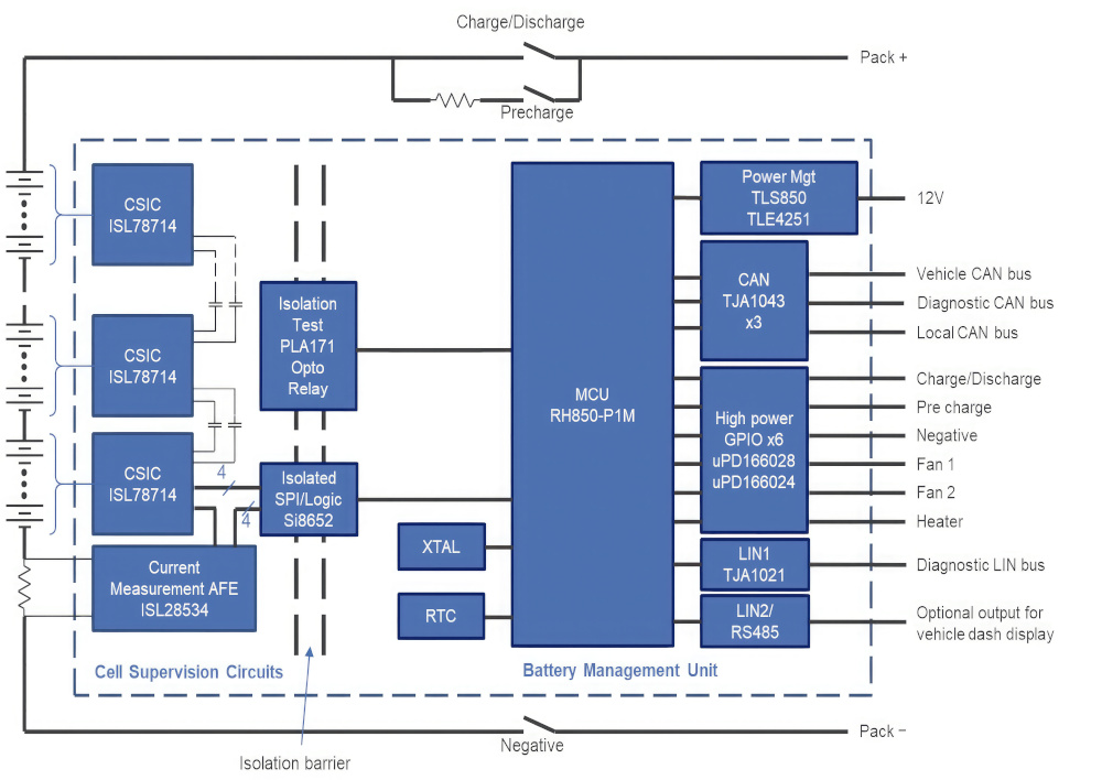
(Courtesy of Renesas Electronics)
Lifetime accuracy
While achieving the required measurement accuracy of 2 mV for the AFE is mainstream now, the coming challenge is to maintain that accuracy for as long as possible. The BMS has to measure the degradation of the battery cells, rather than the reduced accuracy of the measurement chips, throughout 15 years and the temperature range of -40 ºC to +85 or 125 ºC.
Maintaining the 2 mV accuracy at the end of life can extend the guaranteed operation of the pack from 8 years to 10, for example, improving the warranty conditions and reducing costs for the car maker.
One general technology trend for BMSs is a difference in the planned lifetime of vehicles. While there are still designs for a 15-year service life, there is now a growing impetus to produce designs with a service life of 5 to 6 years. That changes the design requirements and drives far more reuse of a BMS, as there is a turnaround of 2 years maximum for a complete new car design, including testing.
Alongside this is the drive to 800 and 1000 V battery packs that are driving higher robustness requirements where the electronics are merged with the battery pack. This brings overcurrent and stress problems, especially if the battery is highly loaded.
The issues are specifically around hot-plug and sequencing during assembly of the BMS during production, as manufacturers want complete freedom in how to connect to the BMS and to use different modules in different packs.
There is a hot-plug requirement during assembly, as there will be charge already in the pack, and the charge can be completely different from one pack to another.
The worst-case scenario is that the components in the BMS are only partly or pre-damaged, and later on after a certain mileage a cell seems to be leaking, but the cell is OK and it’s the chip that is damaged. This is a critical point that manufacturers are learning as they get into high-volume production with more variants and more automation to produce vehicle models with shorter service lives.
Experience from the design of components for braking systems also helps with the robustness for a BMS, measuring voltages down to the millivolt range and sustaining power peaks to several amps with current and voltage spikes. That is not easy to test; it shows up in returns from the field.

Semiconductor manufacturing process technology such as silicon-on-insulator (SOI) that is used for chips in the braking system are used for a BMS. With a bulk standard CMOS process, the higher current from the spikes can be injected into a transistor, causing damage, but he SOI process allows a quick, ‘snapback’ effect that removes the current before that can happen.
The peak current is 5000-6000 A for the whole battery pack, and from the measurement standpoint the BMS needs to be able to measure up to 2000A with 0.5% accuracy in all conditions, in 10 ms, meaning a 10 kHz cycle.
The trend of going up to 800 or 1000 V reduces the battery current, but because the voltage is higher the voltage gradient is much faster. That generates faster spikes, which need to be addressed more quickly with the snapback design.
The higher voltage packs also have more cells. While the measurement accuracy is currently 1 mV for a cell, doubling or tripling the number of cells reduces the time available to make that measurement. That has an impact on the functional safety requirements, as redundant measurement schemes are needed rather than taking a single measurement with internal diagnostics, as there isn’t the time any more for the diagnostics.
That approach ends up with double the data being required for the redundant signal paths. These can be integrated into the same chip but with appropriate measures to prevent the signal chains from influencing each other.
For example, the primary and secondary measurements can’t come off the same pins. BMS designers need to physically change the physical connection to avoid a single point of failure on each side of the package, for example a humidity problem causing corrosion.
This also has an impact on the rest of the BMS design, as sending all the raw data to the main processor requires double the bandwidth and comes with a higher current consumption owing to the high-speed data that has to be transferred in a certain time window.
This is driving more use of wired networks for a BMS, with a large PCB in the middle of the battery packs hosting all the sensing and data conversion, measuring the cell and stack voltage, and the temperature, with redundant signal chains so that the board can be used across multiple vehicle models.
This also reduces the need for processing in the battery pack, which is a high-voltage environment. That is driving an architecture where the microcontroller is outside the battery pack and can be updated more easily if necessary and easily connected to the rest of the vehicle.
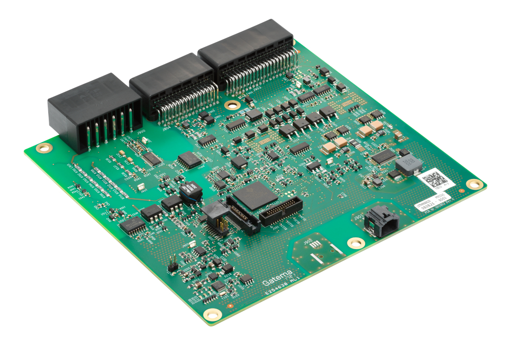
(Courtesy of Renesas Electronics)
Wireless
Bluetooth is used as a wireless technology for BMSs. Bluetooth Low Energy (BLE) 5.1 can provide signal strength information, which can be used for a BMS when the battery pack scales grows in size. That can give the signal strength at the end of the pack or end of a loop
The main benefits of a wireless solution is reducing the cost and weight of the wiring harness. Using BLE5.1 in a star configuration gives the same data rate to sample all the cells in the pack, typically across eight devices each with 12 or 14 channels, in less than 100 ms. That means the same hardware can be used with packs with different topologies across different models.
However, security is an issue with Bluetooth, so extra layers of security have been added to make the wireless network private and non-discoverable, with the unique ID numbers of each wireless node saved in the BMS host when the pack is assembled. That means the BMS will only respond to certain nodes, and certain nodes will respond to other nodes within the pack, so if a hacker tries to gain access they cannot connect.
Another approach uses a proprietary wireless link rather than Bluetooth with added processing in the radio. This is a 2.4G Hz proprietary system that runs up to 100 Mbit/s and includes a range of correction and anti-interference protocols, including CRC.
Using wireless networks for the chassis packs gives more flexibility over the life of a vehicle. For example, rather than replacing a whole pack as determined by the declining performance of the worst cells – which determines how long the pack can be out in the field – a garage can remove the worst cell and make the pack last longer.
(Courtesy of Sensata)
Shipping
The Covid-19 pandemic highlighted other issues with BMSs. Vehicles were held in ships outside ports for months, meaning the batteries became completely drained while waiting and the vehicles could not be driven off after docking. This has led to demand for a ‘ship mode‘ with a lower quiescent current of microamps to avoid discharging the packs and is another reason for using a wireless BMS that can be completely shut down during shipping.
Security
Even with a wired BMS, security is vital, and there are multiple layers of protection, Data is encrypted using standard algorithms to secure the comms link, but the master microcontroller also uses a unique number and timing of packets. The controller counts the number of requests for data, and checks that the number of packets received matches the number of requests in the correct order.
Safety
Some BMS manufacturers have come up with a unique way to allow for flexibility while maintaining original ISO 26262 certification in an off-the-shelf product to meet the specific needs of battery packers.
To achieve this, the BMS software is separated into two layers, the base-layer-software (BSW) and the application-layer software (ASW).
All the safety critical functions and hardware drivers are included in the BSW, which can’t be modified, protecting the functional safety certification of the product. This also contains the non-safety-critical features such as proprietary algorithms for the SoC or SoH.
On top of all these, an ESW (external software layer) allows the end-user to add software features or include their own algorithms. The BSW is separated by an API interface layer, which simplifies the programming and provides the connection between the BSW, ASW and ESW.

Construction and agricultural vehicles
Battery management for construction and agricultural equipment is a major challenge.
The design of a BMS for such applications has to support a wide range of platforms with low-volume production with a flexible architecture that can be used for hundreds of vehicle variants. These can vary from 10 kW skid-steer loaders with a 48 V battery pack to 20 t excavators with a 400 kWh, 800 V pack.
One distributed BMS architecture has been designed to support battery packs from 48V up to 800 V for the largest, with battery packs that scale up to 900 kWh.
This architecture uses 50 V NMC lithium-ion battery modules that can hold from 3 to 9 kWh per module. The key is that the width and height of the module stays the same, all using standard 21700-format cells, but the length changes, with more of the cells added to provide more power and energy. The modules all have the same 50 V output, with a base of cells in series in a string and additional power added by increasing the amount of cells in parallel of each string.
Each module is monitored by a module management unit (MMU), which includes a 14-channel analogue-to-digital converters (ADCs) to take current, voltage and temperature data from each string of cells. This combination and consistency simplifies the production of the pack.
(Courtesy of ELEO)
A flexible PCB is directly welded onto the cells to provide the link back to the MMU and forms the first part of the BMS. The module has positive and negative terminal for the PCB and two connectors for a CAN FD link to a master controller called the pack management unit (PMU).
This PMU is a master for all the modules in the pack, and has safety features; it also doubles as a partial power distribution unit. It can support up to 100 modules for a total power of 900 kWh if necessary and across the range of voltage levels.
For low-voltage packs up to 120 V, or two modules in series, the power for the unit can be derived from an onboard DC-DC converter, while higher voltages need a separate power supply such as a lead-acid battery. The PMU also includes an embedded isolation monitoring device and built-in redundancy for high-power switching up to 400 A.
Those switches are used for a high-voltage interlock so that when the HV connectors to the pack are unplugged the system is already turned off. The PMU also includes built-in isolation monitoring that can detect a single error, such as a corroded wire, by measuring the drop in resistance.
That would then lead to the whole pack being shut down for safety reasons. A single module cannot be switched off independently, as that would change the voltage and the whole system’s performance.
The MMU module management unit includes local processing and data storage for historical data that will be vital for upcoming regulations for battery passports. This storage holds the state of charge (SoC), state of health (SoH) and State of Power (SoP) derived from the battery data using algorithms running locally.
The SoC, SoH and SoP data is sent to the PMU over the CAN FD link. The PMU then checks the performance of all the modules and stores the data to create usage profiles to monitor the performance of the modules over time. The unit is connected to a comms gateway. That uses a wireless narrowband NB-IoT data link to the cloud, sending data in clusters when a connection is available. Each PMU can store around 2 weeks’ worth of data.
The data link is also used to download over-the-air (OTA) updates for the PMU, which can then update all the modules in the system with new parameters, particularly for correcting the SOH indicator.
The OTA update is critically important, as any new software has to be downloaded reliably and securely to the monitor. Any new update is tested in a hardware-in-the-loop system in the laboratory that replicates the battery system to ensure it will work as intended.
The new code is then downloaded to a free area of memory and checked for consistency – this typically takes around 30 seconds. The system then runs from the new code, but the old code is still available in the event of a problem.
New parameters for the MMU for the SoH can be implemented by the battery pack’s developer but bigger changes, such as updating the SoC or SoP data, would require working with the OEM developer.
Machine learning
Neural network accelerators are now being added to the microcontroller to run machine learning algorithms in a BMS. These accelerators can be used to improve the algorithms for the SoH and SoC, and identify potential issues for preventive maintenance. This will take the algorithms from an accuracy of 6-10% accuracy now to 2%.
In some cases the battery makers lease the packs to OEMs with certain warranty conditions, constantly monitoring the packs with a data log and replacing the pack when it reaches 86% capacity.
The cloud
The data is also analysed in the cloud, for a number of reasons, The data is used to construct an internal dashboard where new customers can evaluate different schemes for charging, how they use the vehicles, whether to use larger or smaller battery packs or different charging strategies. This can also provide statistical data to advise what kind of packs are needed for a given piece of equipment.
The next stage is to use this cloud data for remote servicing of the battery packs. The current system allows flags to be set for certain conditions that will require maintenance, for example if there is a growing imbalance in the system and there is not enough time to re-balance it. This allows maintenance to be scheduled and replacement modules to be shipped out in time so that the equipment can keep running in the field.
This cloud data can also be used to extend the internal safety features in a BMS to detect safety-critical situations. By evaluating larger fleet data over longer period of time, it becomes possible to detect anomalies that could indicate future safety risks, which is valuable for asset and warranty management.
In the cloud analysis, data from a battery pack is collected in the learning phase and sent to the cloud to build a model of that particular pack. Later on, as the vehicle matures, a reduced data set is sent to the cloud with local post-processing to assess the health of the pack.
There is still a lot of value in having a digital twin of the specific battery with the right battery chemistry and the performance, as it creates a data model customised to the specific car. That gives a better understanding of the ‘grey zone’ functionality – there is so much margin on factors such as range, which might be specified as 400 km for example, but a vehicle could have a 600 km range.

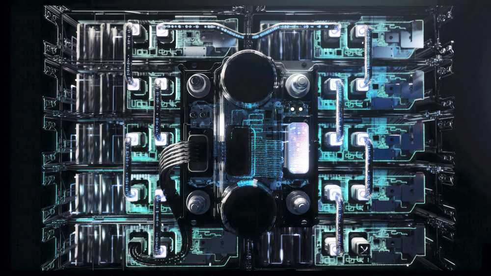
(Courtesy of NXP Semiconductors)
Using a digital twin can reduce that margin to provide more detailed information on the range. It isn’t not about trying to model everything, it is making sure there is proper functional safety to make sure the data you are getting is correct.
The residual value of a battery is also critical. Insurance companies don’t yet know how to value high-end EVs, and the digital twin analysis is much more valuable for the car maker and the owner.
There are now moves in Europe to provide a specific level of information from a vehicle’s digital twin to the whole supply chain, not just for a user but for the battery maker, to help to improve quality.
Delivering the battery data to the cloud opens up a range of other functions, from monitoring the cells remotely to building simulation models. The simulations help engineers make the right decisions fast when designing a battery system, leading to reduced risks, improved reliability and faster time to market.
When engineers are designing battery systems for electric products, the battery has to meet certain requirements, including having the right configuration to fit in the space available and providing the power and energy capacity required for the use case. Above all, the requirements must still be met after years of operation, not just for the first couple of years.
A simulation can look at which cell format and chemistry are best suited to those requirements, along with how much space is available in the application and what that means in terms of how many cells can fit into the space and the cooling system.
This all has an impact on cell ageing, over and above the load and charging profiles, but testing cells to determine all these factors would be time-consuming and costly. Modelling the batteries reduces the need for physical testing, reducing costs involved and speeding up development times.
The cell model is a coupled electrical, thermal, and ageing model. Electric, thermal and ageing factors influence each other – for example, using a battery in higher temperatures will usually lead to faster ageing – so taking all these factors into account provides a more realistic result than with a non-coupled model or one that does not take ageing into account, for example.
The electrical model simulates the electrical performance of the cell, for example voltage and SoC. The thermal model simulates the temperature of the cell. The ageing model simulates the calendric and cycling performance of the cell, expressed in the form of SoH capacity and resistance.
All cells behave differently, so the parameters change for each cell. For every combination of format and chemistry, the parameters of the model change, as a different cell behaviour must be reproduced.
The electric, thermal and ageing components of the battery model are constantly updated with the most recent data. For example, the latest version of the model adds float current measurements in the ageing model and a complete update of the electrical model over the battery’s lifetime using an adjusted model design and measurement fitting technique.
All this data is used to identify the most optimal operating conditions for the battery to configure BMSs and use as input for warranties.

e-bike BMSs
There is also a focus on less expensive BMSs for e-bikes and scooters. One approach has been to use experience from programmable motor controllers, replacing the motor control blocks in the chips with two, 16-bit sigma-delta ADCs for cell monitoring.
These support up to 20 lithium-ion cells in series in a single string using a programmable processor, either a 50 MHz ARM Cortex-M0+ core or a 120 MHz Coretex-M4F core, with more memory that can run more sophisticated algorithms.
The key to the BMS chips is that they are built on a process technology that has a maximum voltage rating of 145 V rather than the more usual 85 or 100 V. That allows packs from 18 to 100 V for e-bikes with cell balancing and monitoring alongside under and overvoltage and temperature monitoring.
The voltage of each cell is measured through the ADC using a sequencer controlled by software in the microcontroller core. The current ADC has a programmable gain and is synchronised to the voltage measurement.
Having the microcontroller core on the chip allows software libraries for the IEC 61508 functional safety to be added for higher energy packs. This would have a third ADC that monitors internal references for the functional safety designs.
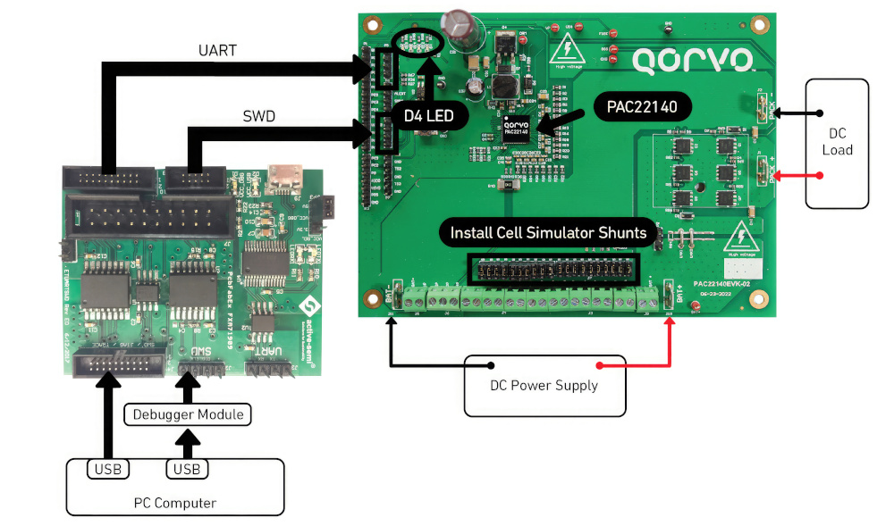
(Courtesy of Qorvo)
Future BMSs
The move to solid-state batteries will also have implications for BMSs. These will have higher energy density and will be more compact, so closer temperature monitoring will be necessary, which this needs to be improved.
The cell voltage can move from 4.5 V now up to 10 V, which will have an impact on a BMS designed with 5 V microcontrollers. A 10 V cell for an 800 V battery pack might not need so many cells, which would make the BMS cheaper, but the chip will need to measure a much wider range, from 1-9 V, which is an additional level of challenge for the accuracy. This is coming though, and BMS measurement chip providers are preparing for that.
Impedance monitoring
The next move for BMSs is to combine AI and impedance spectroscopy., which will use current passed through each cell to measure the internal impedance. This data can then be used with machine learning to provide even more accurate data on the state of the pack.
Monitoring the impedance can help not just derive the impedance but give a more accurate assessment of the temperature, and can be used with NMC, LFP and even sodium cells. The monitoring provides higher levels of accuracy and reduces the safety

Acknowledgements
The author would like to thank Bram van Diggelen, at Eleo, Chirag Patel at ADI, Antonio Leone at NXP Semiconductors, Niall Lyne and Tony Allen at Renesas Electronics, John Carpenter and Brain McCarthy at Qorvo and Zsolt Bernath at Sensata for their help with researching this article
Some suppliers of battery management systems
Germany
Comemso
Infineon Technologies
Innovation Labs
TWAICE
+49 711 982980
+49 89 234 65555
+49 6221 54 19 100
+49 89 997 324 58
India
Maxwell Energy Systems
Italy
Japan
Korea
Lithuania
Netherlands
Switzerland
UK
Eatron
Dukosi
Silver Power Systems
+44 1926 623039
+44 131 445 7772
+44 1793 784242
USA
Analog Devices
Sensata Technologies
Texas Instruments
+1 781 935-5565
+1 508 236 3800
+1 972 995 2011
ONLINE PARTNERS

