


E-motor materials
(Courtesy of Carpenter Technology)
Driving forces
E-motor developers share some best practice with Nick Flaherty about the design and materials that go into their products
The need for low weight and high performance in e-mobility motors is driving a demand for specialist metal alloys and insulating materials that are also thermally conductive. There is a strong focus as well on how they are sourced, particularly with regard to heavy rare earth (HRE) elements.
Dysprosium and neodymium for example are used to boost the magnetic field in permanent magnets, but they can be difficult to source and are expensive. Others, such as erbium, are more freely available, so magnet makers are looking at using those instead, as well as reducing the amount of HREs that are required.
Motor makers are also looking at replacing the magnets entirely with new architectures and control algorithms that provide similar levels of efficiency to permanent magnet machines.
Magnetic materials
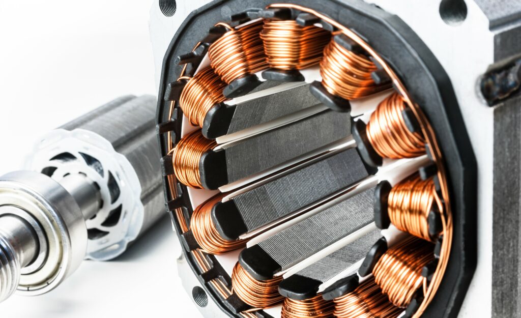
Neodymium magnets offer the highest energy density currently available commercially, and different neodymium-iron-boron alloys have different magnetic properties. The magnets are produced by sintering metallurgical powder and, depending on size, shape, tolerances, batch size and magnetic requirements, they are either cut from isostatically pressed blocks or die-pressed. This produces anisotropic magnets is all kinds of shapes for motors.
The magnets are supplied with different coatings that deliver optimal protection and adhesive performance for virtually any application. These include nickel-copper-nickel, epoxy and even organic coatings. The latter was specifically developed by magnet and magnetic systems supplier JL Mag to give superior salt spray test resistance with adhesion properties tailored for a specific application.
Sintered samarium-cobalt magnets are used when stability is needed at temperatures of up to 250 C for SmCo5 and up to 350 C for Sm2Co17. This is particularly important for motors for electric aircraft (see sidebar).
But there are many other elements used in the magnets for electric motors of all kind, from small e-scooters up to large trucks and aircraft.
“There’s aluminium, gallium, cobalt and 19 different elements – all of them have a small effect on the total performance,” says Jurre Stienen of magnet material supplier JL Mag. “Some elements such as cobalt improve the structural integrity, and from a magnet performance we want to add as much cobalt as possible, but from pricing and availability viewpoints we don’t want to do that. “
“The drive in eliminating HREs is mostly tied to volatility in their prices,” he says. “There was a price hike in 2011 from 100 to 200%, in 2014 from 100 to 130%, while in 2019 their scarcity from a trade war pushed prices from 100 to 115%, so the spikes are getting smaller. Customers are also pushing for stronger magnets that they can use as a construction part and that use less cobalt, so they are not as strong.
“We use HREs where they are needed, which is only in the grain boundaries of the magnet, so you can save a lot on the elements you need.
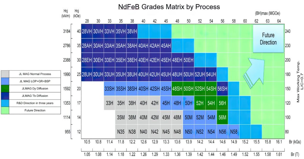
“Automotive applications tend to use the SH, UH and EH grades, which are stable up to 200 C, and which grade is used depends on the cooling of the motor. The 35EH 1.2 Tesla-grade material is the sweet spot for developers, 50EH provides more magnetic performance, at 1.4 T for 15-20% more power but with more rare earth material, so that costs 30% more. We are developing 52EH and also a 55UH grades.”
The 52EH and 555UH will have a higher magnetic performance but higher cost of the material itself might not translate into a higher motor cost.
“If you have 15% more performance in the same volume you can make the entire magnet stack shorter, which means the rotor and the machine can be 15% shorter,” he says. “That compensates for the small increase in price. Using rare earths at the surface of the magnet will see only a 5% price increase but it will save a lot on the rest of the motor.”
The magnets also have to be glued onto the rotors and held in place by fixtures, and the coating material used on a magnet is key for the adhesion. “For the fixtures we try to get the best glue adhesion possible,” Stienen says. “We have slightly altered the coating process to get a coating adhesion of over 40 MPa – if we are going higher than that the forces are pulling the magnet apart.”
(Courtesy of JL Mag)
Non-rare earth designs
Motor designs that avoid the use of rare earth elements are now coming to market. These designs require higher levels of optimisation of the motor with the control controller.
“We want to produce simple e-machines with lower cost,” says Paul Price, CTO at motor designer IRP Systems. “For that we need to bend the rules of controls, which means making them more sophisticated. Without rare earths there are issues with control, power electronics, size and weight, all of which need to be optimised, so we are doing both control and e-machine design.”
The issue of rare earths has even driven automotive parts manufacturer Mahle to develop a new kind of magnet-free electric motor that does not require them.
Dr Martin Berger, head of r&d and advanced engineering at Mahle, says, “Our traction motor does not use magnets but generates the magnetic field using an excitation coil in the rotor, so the production of the motor is independent of the raw materials markets. The power to the inside of the motor is wireless and so is wear-free. The motor operates with 96% efficiency, and we can scale it easily form small test cars to commercial vehicles.
“To get the energy to the rotor, it uses an AC field that is converted to DC for the magnet coils that induce a magnet field into the air gap,” he adds. “The magnitude of this field can be controlled easily.
To achieve this change in material, Mahle simulated various motor designs, adjusting different parameters until an optimum was found. This approach is much faster and cheaper than conventional physical prototyping
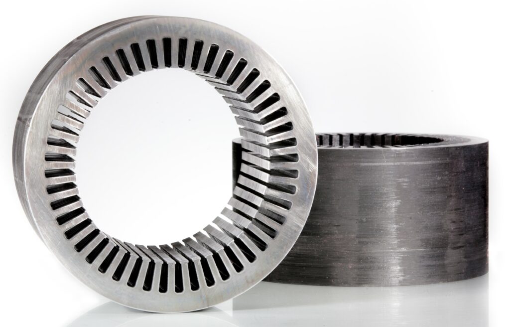
Stator materials
A stator is built up of very thin layers of specialist steel, with a balance struck between the thickness of the metal and its structural rigidity.
The layers are made as thin as possible to reduce the eddy currents that are induced by the magnetic field and cause heating. This heat reduces the efficiency of the motor and needs to be removed from the rotor, often by a liquid cooling system. However, other materials such as insulating layers between the lamination layers can also be used to take heat away from the stator.
The steel used for the rotors and stators in motors for electric aircraft and high-performance vehicles is different from mainstream designs, the aim being to provide the highest magnetic performance and strength in order to achieve the lowest weight.
“Most alloys are silicon steel, but we use a cobalt-based alloy in stators and rotors,” says Nir Vaks, global director of magnetic materials developer Carpenter Electrification. “Using a lot of cobalt means you can push more magnetic flux density through the alloy core, and the more magnetic flux you can push through the alloy, the more power you can generate.”
The alloy in each layer of the lamination in the stator can be as thin as 0.002 in (a thickness grade of 002) up to 0.014 in for a high-performance motor.
There are three tiers of processing for the cobalt alloy. Carpenter’s proprietary chemistry produces the mechanical strength in four grades, from HC 27 for e-mobility motors, 50 and 50A for aerospace, to 50HS for higher strength but a lower magnetic capability.
Then there is a hot and cold rolling process followed by heat treating the alloy with temperature cycles and quenching. Carpenter uses a hydrogen-rich environment that allows more control of the mechanical, thermal and electromagnetic properties.
The HC 27 grade contains 27% cobalt that supports a flux of 1.8 T flux, rising to 49% for the 50 grade, while the 50A has additional niobium to support a magnetic flux of up to 2.3 T and 50HS has vanadium, giving higher strength but a flux of 2.2 T. There are also other trace elements that are important for the structure of the grains in the metal.
As Jaydip Das, senior manager, Applications Engineering, at Carpenter Technology, explains, “We add vanadium and sometimes manganese to refine the grains, and it is the post-process heat treatment that defines the combinations for 50A and 50HS. Larger grain gives higher magnetic permeability and lower losses but less strength.
“On top of that you can tweak the grain boundaries and size to control the distribution of the grains. For example, if you want a high strength area you make sure this has smaller grains.”
The laminations are combined in a stack, but there is a trade-off between the bonding materials and methodologies and the fixture ring to maximise the mechanical strength and the magnetic performance, says Vaks. The metal in the moving rotor for example has to be stronger than the stationary stator.
The materials for the fixtures to hold the magnets in the rotor together are also changing. Rather than using steel ,which is susceptible to eddy currents and heating, a thinner carbon fibre sleeve can provide the strength required with less weight.
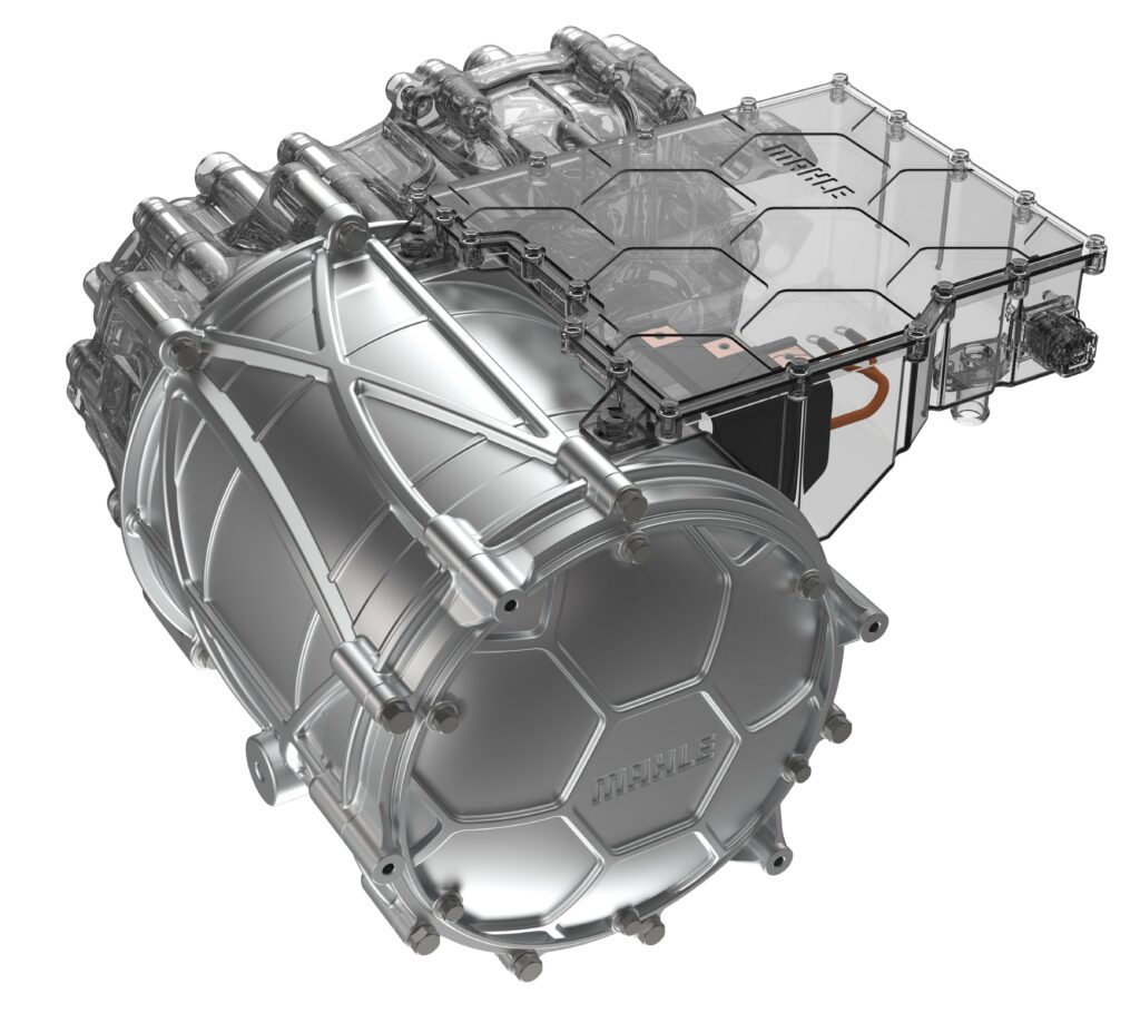
(Courtesy of Mahle)
Rotors
The design of the laminations in the rotor can generate different profiles of magnetic flux to mimic an IPM or SPM motor with different levels of performance.
“We are using different designs of windings and different design of architecture of the steel for the flux from the outside,” says Price. “We are looking to replace copper, which would mean you wouldn’t have to manufacture wire or hairpins, so you can cut the number of processes.
“In the future, we will use a different winding system and a different process for applying those windings. These are cast windings, which are easy to manufacture, but you need optimisation in the inverter to manage that. That needs to be implemented in e-machines in the future, and it has to be designed at a system level for cooling to dissipate the heat so that you can have an air-cooled motor rather than a liquid-cooled one and still get the performance.”
(Courtesy of Carpenter Technology)
Adhesives and coatings
The adhesives and coatings used in e-mobility motors are also critical to the performance of the motor, particularly for the thermal characteristics and the need for thin but rugged insulation and protective coatings for reliability.
“In the future stator and rotor designs will see a rise in voltage to 800-1200 V to reduce the charging time of battery packs but the problem is to have that voltage and a high current in a small space,” says Christoph Lomoschitz, global product manager for energy solutions at coatings supplier Axalta.
“We now see effects from high-voltage generators happening in the powertrain motors, such as increased heat dissipation and partial discharge effects, and this impacts on the materials that have to withstand high temperatures for long periods of time,” he says.
“The intrinsic resistance of copper windings rises with temperature, so there is a demand to keep the temperature low, but the more current that flows through the wires, the higher the temperature,” Lomoschitz says. “We can overcome that by lowering the thermal resistance, reducing the thermal flux barrier through the stator core into the cooling loop to keep distances low or integrate the cooling loop into the stator core. We also need a lamination coating for a compact seal of the core so that the cooling liquid does not leak.”
The insulating materials developed by Axalta are based on a polymer resin with a ceramic filler. This is to increase the thermal capability as well as find a way for the material to flow evenly without creating voids or air pockets. The filler has a density of more than 50% of ceramic particles to ensure that the particles connect to transfer the heat.
“We impregnate motor windings with a resin that has 2-3x higher thermal conductivity by doping the material with inorganic fillers,” Lomoschitz says. “That creates viscosity abnormalities or flow problems, and you can end up with air gaps. This is the worst thing as it’s an ideal heat insulator. Our material is designed to be applied as a standard resin, so it flows well and doesn’t need special equipment or specific application parameters.”
The choice of the viscosity of materials such as Axalta’s Voltertex 4224 depends on the motor design and the gap width between the wires or the wire to stator. The thinner the gap, the lower the viscosity of the material should be, but this also depends on the impregnating process.
Some processes apply certain forces to move the resin. For example, a trickling process requires a low viscosity material as gravity and capillary action is used; with a dip and bake, where there is air pressure, or with vacuum impregnation, the viscosity is less important.
The thermal setting time of the resin is also a factor, as it determines how much time is available to get the material into the gaps. To reduce the cost of the assembly, this has to be fast, implying a lower viscosity and lower thermal performance. The challenge is to develop a material with high thermal conductivity that fills small gaps quickly and cures in 30 minutes rather than 90.
The coatings and adhesives used in the stator are usually waterborne and heat-cured, and are there to insulate the sheets to reduce eddy currents. Using an adhesive avoids the need for interlocks or welding rods to hold the stator lamination layers together.
The coating eliminates the air gap in the laminations for smoother distribution of heat, and can seal the stator core and give it a certain resistivity and protect against leakage. This approach allows holes to be drilled into the stator that can act as cooling channels.
The coatings are applied to the stator steel in a steel mill, and brought to a dry but active state. The stator steel is shipped to a company that punches out the laminations and builds the stator stack, bonding the laminations with an oven cure or induction cure.
The key factor is to keep the adhesion at a continuous high temperature, of between 150 and 180 C, with a peak temperature of 230-250 C.
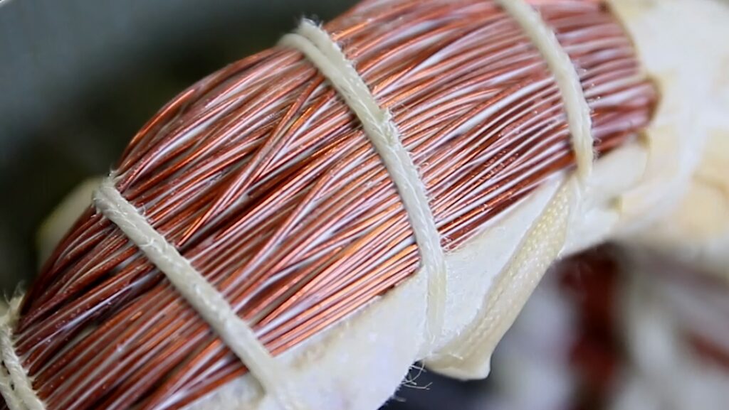
Wire enamel is applied to magnet wires to avoid damage from partial discharges. The higher voltages with shorter rise times lead to higher peak-to-peak voltages and more partial discharges. A standard enamel coating would last about 30 minutes before the discharges broke through to the copper underneath and damaged the rotor. The enamel has to last 1000 hours at the same coating thickness of 100 microns as used by the standard material.
To a large extent, the partial discharges are generated by air voids in the slots of the rotor, so a good process of impregnating the rotor with the insulating resin material is key to avoiding them, but coating the wires with enamel gives a longer period of service. The impregnating resin will also protect against discharges, as the ceramic density slows down the erosion of the material.
The enamel materials are also used to protect the welding of hairpin and eye pin rotors, where the ends of the wires are stripped, inserted and welded again but need to be re-insulated.
(Courtesy of Axalta)
Manufacturing process
Reducing the cost of a motor also means reducing the number of manufacturing processes, but that number of processes also depends on the materials used. A simpler manufacturing process allows the motor to be assembled alongside the rest of the vehicle.
“If you make an e-machine using fewer processes and components you will be able to build micro-factories for the motors,” says Price at IRP Systems. “You can then produce them at the destination on demand but that can only happen if the machine has a simple design.”
Polymers
Using recycled materials in the motor is also important for lighter housings; they are easier to produce using injection moulding. That allows production closer to the end-market, as well as local recycling, as the temperatures used for recycling and manufacturing them are much lower than for steel or aluminium. This is aimed particularly at lower performance personal mobility systems such as delivery e-bikes and e-scooters
Conclusion
Achieving the best possible efficiency, power-to-weight ratio and cost of assembly of an e-mobility motor is about much more than just the materials in the magnet. New processing techniques are reducing the amount of HREs in the magnets while still allowing the motor to be smaller.
Other combinations of HRE materials support higher temperature operation for higher efficiencies in generators and motors on electric aircraft. Using a carbon fibre sleeve avoids the eddy currents produced by using a steel jacket.
Other designs are removing the rare earth materials entirely and relying on more complex control algorithms to compensate for the lower performance while achieving a more cost-effective construction. Other still are removing the magnets entirely to boost reliability.
Achieving thinner laminations of the stator steel boosts the performance further, while materials with higher thermal conductivity can carry the heat away, and adhesives can allow more effective cooling channels to be built in the stator.
Different wire topologies in the stator boost efficiency, while other designs aim to eliminate copper wires entirely and use a single cast coil for simpler, more cost-effective construction.
The use of recycling polymers formed at lower temperatures than steel or aluminium will also allow motors to be constructed closer to where the end-vehicle is assembled, boosting local supply chains and reducing the cost and complexity of e-mobility machines of all kinds.
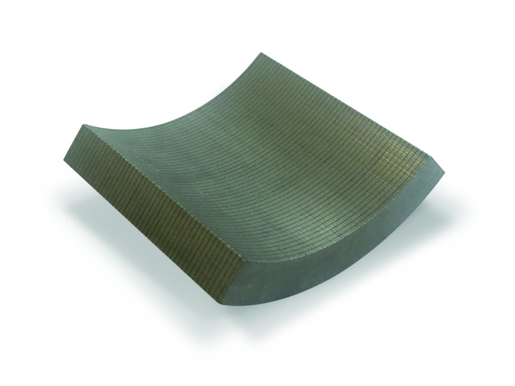
(Courtesy of Arnold Magnetics)
Materials for motors in electric aircraft
Rare earths are key to the performance and efficiency levels needed for electric aircraft. This means attention has to be paid to the supply chain for them.
“We are trying to establish more rare earth suppliers with a UK and EU supply chain,” says Aaron Williams, director of strategic technology and business development at magnet supplier Arnold Magnetics. One way to do this is by recycling existing magnet materials to extract the rare earths.
The motor also has to be as light as possible though, while cost is less of an issue. This leads to the use of carbon fibre rather than steel for the sleeves that hold the magnets together, cutting the weight by half. It also avoids losses and heating that come from eddy currents in the steel sleeve.
Using a lightweight, strong sleeve also allows different magnet topologies to be used, such as the Halbach design. This was developed in 1970 and uses a complex configuration of magnets to ensure all the magnetic flux is directed into the centre of the motor. This is achieved by aligning the magnets so that the flux is cancelled out on one side and therefore boosted on the other side.
“This gives 3 to 8 percentage points higher efficiency,” says Williams. “Our Recoma material uses samarium and cobalt to be stable at the high temperatures in aerospace, as when a neodymium magnet gets hotter it gets weaker, and it has a maximum temperature of 200 C. A samarium-cobalt magnet can operate up to 350 C, which is higher than any motor can operate as the wires and varnish would melt at that temperature.”
The magnet can also be laminated to reduce the losses from eddy currents. The magnet layers are 1-2 mm thick, and a proprietary epoxy designed to bond to the coating on the magnet is used to bind the layers together.
The operating temperature is also an important design factor, as there are other ways of generating electric power in aircraft. “Where we need to get to is small and single-aisle aircraft and they will need an auxiliary power unit burning jet fuel to drive a 2 or 3 MW generator to produce power for the electric motors,” says Williams. “Our focus now is to make the generator and motor as efficient as possible.”
The topology for a permanent magnet generator is different from that of a motor as it runs at one optimum speed with less need for control. “Then it’s about making the rotor and stator as efficient as possible, by reducing the losses from the bearings and the heat generated in the eddy currents, so we try to optimise the slot fill on the stator,” he says.
The slot fill factor is the amount of copper wire in the slot in the stator, and one way to increase this is to have even thinner laminations in the stator than on other e-mobility platforms. These laminations are produced using a cold-forming process from a base of M19-grade steel. Although there is less focus on cost for an aircraft motor, using a thinner steel is more cost-effective than a high cobalt steel, Williams says. There is another approach called Litz wire (named after the German word for braiding) that can also improve the fill factor. Rather than using a single copper wire, the Litz wire consists of many thin wire strands, individually insulated and twisted or woven together in a carefully designed pattern. For AC at frequencies above 1 MHz, that means most of the current is carried on the surface of the wires, minimising eddy currents and reducing the resistance and heating effects in the wire. The particular design of the weave of the wires can be optimised for the shape and arrangement of the slots on the stator to further improve a motor’s efficiency.
ONLINE PARTNERS

