


Magnetics
(Courtesy of Laboratorio Elettrofisico)
Making electric motors more efficient means looking beyond the magnetic materials and switching techniques, as Nick Flaherty explains.
Power of attraction
The development of the first rare earth magnets in the 1960s by scientists at the US Air Force Materials Laboratory introduced a key new capability for e-mobility. Combining yttrium and cobalt in an alloy for the magnets, then moving to combinations of neodymium and samarium-cobalt, produced much higher levels of performance than previously possible and led to a whole new generation of motor designs.
Rare earth materials can be a challenge to mine, however, and the resulting magnets are more expensive than non-rare earth designs. Also, rare earth magnets can be brittle and vulnerable to corrosion, so often have to be plated or coated with more durable materials such as nickelcopper-nickel, but that impacts on the ability to fix and magnetise them in a motor.
However, the design of the magnetics isn’t just about optimising the performance or reducing the size or cost of the motor in isolation. Making a motor more efficient, even if it is larger or more costly, can bring significant reductions in the size and cost of the battery pack, boosting the overall performance of an EV.
This is a considerable challenge for the magnetics in a motor, which typically has 19 different elements, all of which have a small effect on the total performance. Manufacturers want to reduce their reliance on rare earths such as neodymium and samarium, and heavy rare earth (HRE) materials with a higher atomic number such as dysprosium erbium and terbium.
These can be in short supply or sourced from politically unstable countries, creating problems in the supply chain. This is of concern to car makers, who need a reliable supply of magnets for series production.
Switching techniques for the coils in the motor can also impact on the design of the magnets.
The magnets also have to be fixed in place and then magnetised. Adding more cobalt to the magnet makes them stronger and easier to fix in place, but cobalt is a key material that manufacturers are looking to reduce or eliminate. This means new ways of fixing the magnets could provide advantages, especially in the magnetisation process.
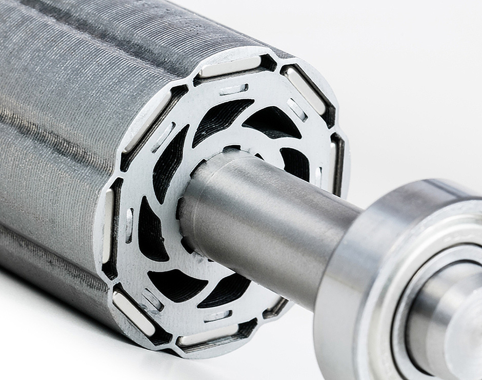
(Courtesy of JL Mag)
Performance
Permanent magnets (PMs) are popular options for motors, as the total weight of the motor is less than other approaches. For example, while the magnets are slightly more expensive than, say, an induction motor, they give a higher performance, of around 9%. That means a vehicle with a 700 km range using an induction motor needs a battery 7% larger than one with a PM motor, meaning extra cost and weight in the vehicle.
So remanence and coercivity are the main drivers for magnet development to maintain the performance while minimising the extra cost. The remanence (Bh) is what remains in the hysteresis loop when the field is applied and removed, while the coercivity (Hcj) is the magnetic field needed to neutralise a saturated permanent magnet.
To get higher coercivity at the higher temperatures that are used in motors in EVs requires HRE metals, but only in specific places. A magnet built entirely of HREs would actually have a lower remanence than today’s magnets.
The grains of a magnet and their alignment are key. A small grain size, produced using a technique called grain refining that also aligns the grains, drives up the coercivity but without increasing the remanence.
New designs of magnet put these HREs in the grain boundaries using grain boundary diffusion (GBD). This is a power diffusion manufacturing process that dramatically reduces the amount of HRE materials needed in a high-performance magnet.
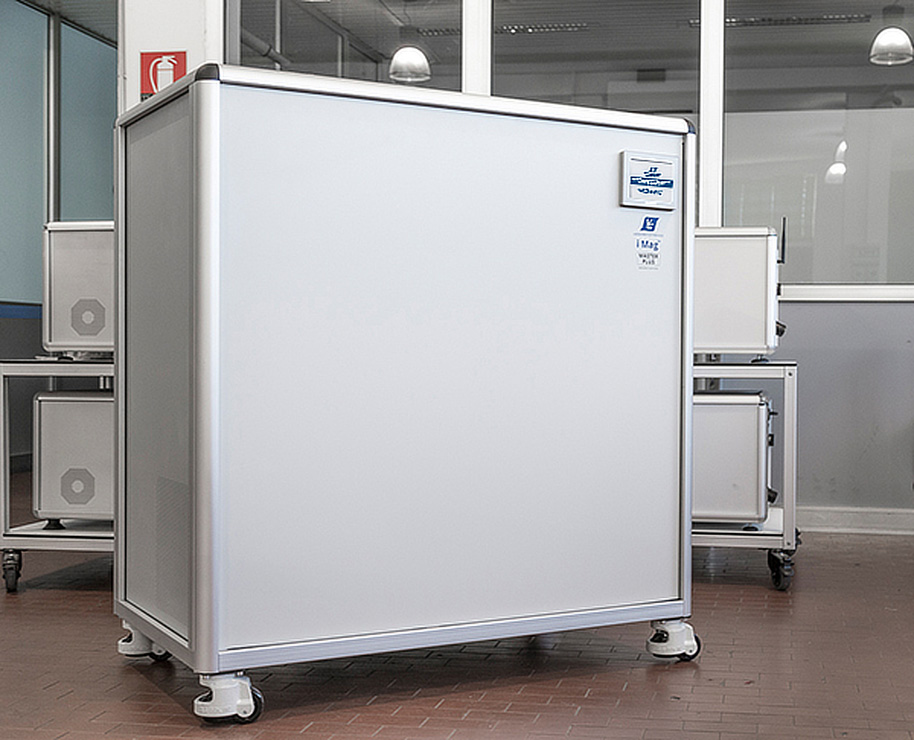
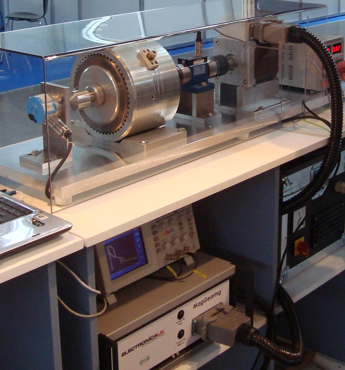
Magnets are installed in powertrain motors and then magnetised by strong magnetic fields
(Courtesy of Laboratorio Elettrofisico)
Classification
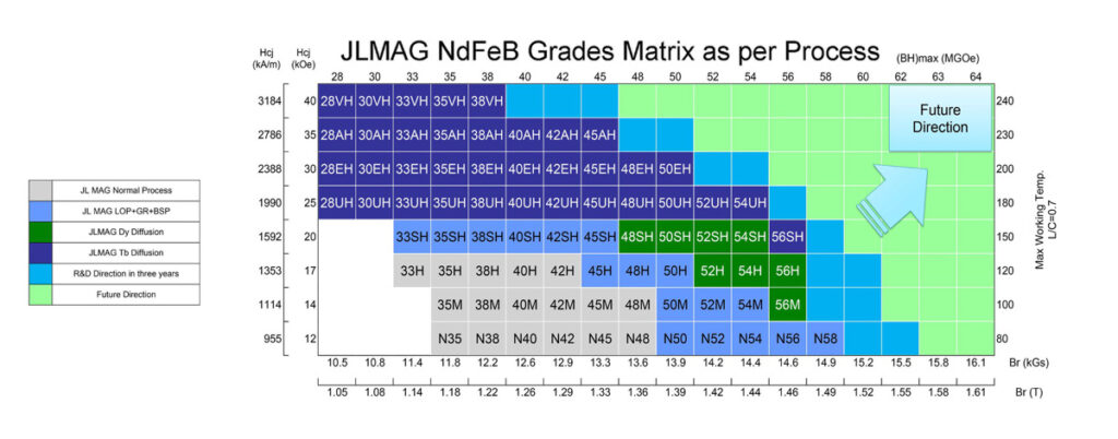
The classification of neodymium magnets is based around the energy product. For example, a classification of 35EH means an energy product of 35 and a flux density of 1.2 T. The higher the number, the higher the magnetic performance.
EVs tend to use the SH, UH and EH grades that operate in the 180-200 C range, although this can depend on the cooling in the motor and the weight ratio of the magnets.
The 35EH grade has been popular for motors in recent years, but designers are pushing to 50EH, which has a flux density of 1.4 T, giving 15-20% more performance in the motor.
There are a number of ways GBD can be used to push the performance of a magnet up to 50EH, or it can be used to build a 35EH magnet with less HRE material such as dysprosium and terbium, potentially giving a reduction of up to 30% in the cost of the magnet.
That 15% increase in performance in the same volume makes the entire magnet stack shorter, so the rotor and the machine can be 15% shorter as well. The increase in price for the magnet using the additional HRE materials is around 5%, but that is compensated for by a reduction in the amount of copper, sheet metal and cooling, which leads to savings in the rest of the motor.
Removing HRE materials in the magnet is possible for the 45SH and now the 48SH grades, but with motor makers pushing for 50EH, those elements are still needed.
One of the aims of the magnet makers is to reduce the weight but maintain the performance. Cobalt is key for structural strength, but there are problems with sourcing the material reliably, although less so than the challenge battery makers face in removing cobalt from lithium-ion cells, in which it is a key component.
Cobalt improves the high-temperature behaviour, as the remanence will fall less with higher temperatures. For example, an EH grade at 200 C gets a 2% performance boost using more cobalt.
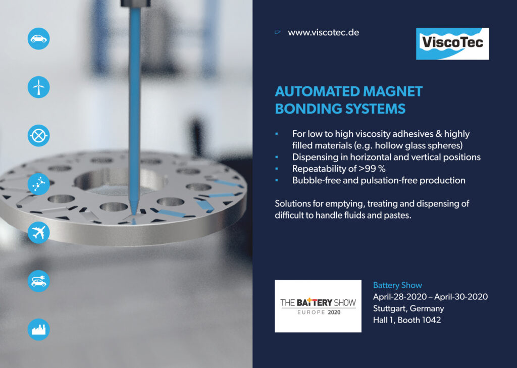
This also influences how the magnet is fixed in the motor, and magnet makers look closely at the material of the magnet, the surface and how to get the best glue adhesion possible. Altering the coating process on the magnet can give a coating adhesion of more than 40 MPa – over that value and the magnet itself tends to come apart.
The magnets can also be vulnerable to corrosion, so different coatings such as epoxy, nickel plating or Parylene can be applied. The success of the coating depends on the quality of the material in the magnet, however, while the adhesion depends on the quality of the coating.
For non-HRE magnets, manganesebased alloys look promising. Manganese aluminium has a high magnetic moment, large magneto-crystalline anisotropy for high magnetic flux and good machinability, as well as low costs and wide availability of the materials.
A 60/90 kW switched winding motor designed to fit in a vehicle for testing by 2021
(Courtesy of ePropelled)
Switching
Another way to reduce the size of the magnet needed in a motor is through switching. One of the ironies of a PM design is that the field needs to be reduced to get the motor to start moving. This field-weakening, applying a field from the rotor against the permanent magnet, reduces the efficiency of the motor.
One approach to address this is to use electronic magnetic gearing, which has a winding inside the electric motor that can be reconfigured while the motor is running.
Starting the motor needs a high starting torque, which can be achieved with four windings in series, each with 10 turns. This needs less current to give the same torque than when the motor is running, as the torque is proportional to the number of turns.
Once the motor is running and the vehicle is moving, the windings are reconfigured to provide 30 turns, then 20, then 10 in parallel. The speed range increases, as with a mechanical gearbox.
The windings are all linked to an array of semiconductor switches to manage the change in the windings. This means there is no need for field weakening.
A key advantage of this approach is that the batteries are not subjected to high current drain when the motor starts up, as the current through the switched windings is a quarter of that of a single winding. This means the battery pack lasts longer for a single charge, and the overall health of the pack is improved.
For example, a 1 Ah battery pack drawing 1 A will run for an hour, but if it’s drawing 100 mA it will run for longer than the 10 hours that might be expected. The same applies to a vehicle battery pack. Avoiding the high current drain increases the efficiency of the motor, extending the range and the lifetime of the battery pack.
This technique allows a motor designer to use smaller magnets with the same size battery pack, or the same motor with a smaller battery. The battery pack is far more expensive than the motor, so the design of the magnetics is a system-wide design optimisation.
(Courtesy of Windings)
Magnet retention
Holding the magnets in place is a critical consideration for design engineers. To optimise performance, the designer must keep the magnets as close as possible to the stator windings; minimising the air gap – the distance between the rotor and stator will maximise torque. The drawback is that as the air gap decreases, manufacturing difficulty increases, and in a non-linear fashion.
Increasing the efficiency puts tremendous pressure on motor manufacturers. Initial efforts to increase efficiency were focused on magnet wire material and rotor designs, followed by the use of external variable-frequency drive electronics to control acceleration and minimise inrush current during start-up. More recently, designers have incorporated PMs in rotor designs to further boost electrical efficiency.
These interior permanent magnet (IPM) designs embed the magnets into a stack of magnetic steel laminations bonded to the rotor, so there is little concern about the retention.
In a surface PM design the magnets on the outside of the rotor have higher performance, as the magnetic flux is not buried in the rotor, but the magnets need to be held in place with a very strong and reliable adhesive to prevent movement or breakage. With rotation speeds of over 10,000 rpm, however, they also need another retention method, and this can be a key design challenge.
The air gap has a major impact on performance. The closer the magnets are located to the windings, the higher the torque output produced by the motor. Any material added between the rotor magnets and the stator windings increases that distance and thus decreases power output of the motor.
To minimise the air gap and still secure the magnets, any retention method must be extremely thin, strong and inflexible. It must withstand sudden torque spikes during rapid acceleration and deceleration, as well as sustained centrifugal forces at higher speeds, while maintaining its properties across a broad range of temperatures.
At higher performance levels, adhesives are not enough to retain the position and integrity of surface mounted magnets for the expected life of the motor, so motor designers have started wrapping the rotor assemblies with other non-magnetic materials in case the adhesive fails.
This process, called roving, uses materials such as fibreglass, Kevlar and Inconel to create a sleeve around the magnets to hold them in place without reducing the magnetic flux. These can add protection but can still fail in high temperatures and at tens of thousands of rpm.

Another technique is to use a metal sleeve that can make use of eddy currents from the stator to stop highfrequency fields from penetrating the magnets and generating losses. Most of the absorbed energy in the metal sleeve is readily dissipated to the cooling medium in the air gap, and the rest is conducted to the magnets or the end supports, helping to keep the magnets cool.
The most common metal alloys used in retention sleeves are ANSI 361L stainless steel, Ti6A14V titanium alloy, and Inconel 718.
Yield strength and material density determine how well a sleeve material will perform under stress. Stainless steel grades similar to 361L are the least expensive option but have low yield strength and high conductivity compared to the other alloys. This can also be expressed in terms of specific strength (yield strength divided by material density). Materials with higher yield strength and material density allow higher rotational speeds.
Carbon fibre sleeves are much stronger and lower in density than the metal versions, and allow for larger magnets in a given design. They can provide a smaller magnetic gap and better magnetic performance but without the frequency blocking. Their low thermal conductivity also means they act as a thermal barrier to the heat generated in the magnets, keeping the heat in.
Manufacturability is a key factor. The most common method of fitting metal alloy sleeves over PM rotors is to machine the inner diameter of the sleeve to closely match the outer diameter of the rotor, to create a heat differential between the two parts (heating the sleeve, cooling the rotor, or both), and assembling them while the sleeve is slightly expanded. Once the assembled unit reaches a stable temperature, the outer surface of the sleeve may require further machining to meet the stator’s specifications.
Metal alloy sleeves can be made separately from the rotors before assembly. This provides an advantage for manufacturers. The sleeves and rotors are machined parts, and the sleeves can be made elsewhere, allowing the maker to outsource one part of production if necessary.
Roving material properties are similar but not identical. Yield strength and density depend on the size and number of fibre strands, or tows, as well as the winding of multi-filament tows directly over the rotor. This takes place under conditions in which temperature, tension and time are tightly controlled.
Thermal conductivity is lower for synthetic materials than for metal alloy sleeves. The greater the rotor coverage by roving, the higher the potential for heat retention. Once cured, roving has a very low coefficient of thermal expansion. Resistivity is much lower for roving than metal sleeves. It therefore has low eddy current losses.
Manufacturability may be the most important difference between these two magnet retention methods. Carbon fibre roving must be heated to its glass-liquid transition temperature but not reach its melting point. The material itself can be very expensive and, because it must be applied in-situ, carbon fibre roving requires additional manufacturing capabilities.
Magnetisation
Permanent magnets do not generate a magnetic field straight away; after manufacture, they need to be magnetised. Here, a high-strength magnetic field of several hundreds of kA/m charges the material and gives it its magnetism. The resulting strength of the magnet depends on the combination of materials, size and the surrounding magnetic circuit.

This magnetisation process is key for manufacturing. Magnets could be magnetised individually and then assembled, but being able to assemble them beforehand on a machine with passive metallic blocks and then charge them is much easier than trying to mount up the already highly magnetised material.
In addition, the magnets can be fixed in place with adhesive, and sometimes this requires a heating process that can partially demagnetise the magnets and so impact on the performance of the motor.
The design of each motor or actuator is also different, and this has a major impact on the design of the equipment needed for magnetisation. The shape and material of the magnets, the temperature, and the shape of the rotor or stator (generally only one side of the machine has magnets) all affect the quality of the magnetisation process.
If a design can’t be fully magnetised, such as with a spoke configuration, then using some conductive parts near the shaft or reducing the depth of the magnets makes it possible to reach full saturation.
The magnetising process has to be fast for an automated production line, and the final level of magnetisation also needs to be tested to check that the machine is performing as designed.
The design of the magnetisation equipment has to be customised to the magnets and the machine, as it depends on the material. For example, neodymium alloy-based magnets have a very different response compared to samarium cobalt alloys, and need different field strengths.
If the magnet is surrounded by iron in the device and by the magnetisation fixture, then the saturation field required is much lower, especially for neodymium.
The magnetisation field is generated by a coil driven by a large capacitor and high-voltage pulse generator, and a fixture fits into the motor. The design of the fixture is based on calculations that ensure the magnets in the motor reach saturation.
The voltage of the pulse generator is increased step by step to produce a series of ‘shots’ of magnetisation. After each shot, the magnetic field of the assembly is measured using a sensing coil connected to a flux meter, and the process is repeated until the components are saturated and the magnetic field exerted by the magnets reaches a maximum.
To check that this has been applied reliably, magnets from a test sample can be removed from the customer’s product and measured on their own. They are then placed in a very strong field, of 5-6 T, and the exerted field is measured again to ensure that the magnets can’t store any more energy, which means they are fully saturated.
The design of the fixture can be challenging, as it can be hard to reach every part of every magnet in the machine equally. For example, an eight-pole rotor using neodymium magnets and with a 200 mm outer diameter would need the field to be generated at a depth of 20-30 mm inside the rotor itself, and in theory would need to be magnetised to 3.2 T. However, rotors are usually made of electric steel, so the field needed can be half that, which can save significant power and cycle time in the magnetisation process.
Optimisations
The main area for optimisation is to reduce the amount of material in the magnets, with a configuration to guarantee the saturation. If a design can’t be fully magnetised, such as with a spoke configuration, then there are others that can be used, such as U, VV or C shapes that can be used to get full saturation.
Batches of magnets from a vendor can also vary in performance, which is why the magnetisation process is not standardised. The materials can be slightly different in each batch, so a higher or lower field is needed to give full saturation.
The temperature can also make a difference, both to the magnets and on the production line, as the magnets and the metal can heat up in a high magnetic field. One example is where a rotor was magnetised at room temperature but failed to saturate. After days of testing, the engineers found that the process worked at 90 C rather than 20 C.
The magnetisation cycle is tuned not to exceed 60 C on the fixtures to avoid softening the epoxy glue, and to keep the temperature down the fixtures are cooled.
A new technique called pdqb allows higher frequencies and smaller magnetics to be used in the transformer of a charger
(Courtesy of Murata)
Charging stations
An emerging transformer technology for high-power, high-frequency applications such as high-speed roadside chargers uses a novel winding technique. A patented winding technology called pdqb makes it possible to construct high-frequency transformers of up to and over 400 kW that can operate at frequencies as high as 50 kHz.
This higher frequency allows smaller magnetics and inductors to be used to create a 100 kW transformer in a 18 x 21 x 25 cm package size.
The transformers can be designed with turnings ratios from 1:1 to 10:1 with multiple secondary windings, and are capable of handling input and output voltages in the 50 V to 1 kV range.
The technique avoids problems with skin and proximity effects, and has an isolation voltage of up to 10 kV. The leakage inductance is highly controllable, and interwinding capacitance is low, both of which enhance performance in customers’ designs.
Thermal performance is also improved, eliminating the space requirements and costs associated with heat sinks in charging stations.
An array of 128 x 128 Hall effect sensors allows the magnetic properties of a motor to be easily measured
(Courtesy of Magcam)
Testing
Measuring the performance of a PM is another key challenge for designers. Single sensors using the Hall effect that produce an output voltage depending on the magnetic field are a basic way of testing. Using an array of Hall effect sensors with software can provide high-speed sensing within 80 µs and with an accuracy of microtesla.
This array of 128 x 128 sensors measures 12 x 12 mm, and can be used to measure the magnetic properties of a magnetic assembly or a motor. It can read the field at every point on a magnet and at every depth, such as 1 mm and 7 mm, with just one measurement. The array also enables the measurement of the angle of the field with a 0.1º accuracy.
While knowing the field is helpful, it is the variation in field strength and angle across the whole magnet that is essential. This can be used to detect microcracks that are not visible to the naked eye, not just in the lab but in high-volume production.
It can also be used for measuring cogging torque. Different motor designs have a problem with cogging torque, and that relates back to mechanical problems. Identifying these problems helps the production process and improves yield.

There are two areas of improvement for the measurement systems. One is to measure the field inside the motors, which would use a linear array of Hall effect sensors less than 5 mm in diameter rather than a square array. The other is the software development.
Algorithms such as Fourier analysis on the data from the array can also provide more insights into the state of the magnets.
The construction, design, fixing, magnetisation and testing of magnets for e-mobility applications is a complex chain. There are different optimisations across the magnet and system design for weight and range and across the manufacturing process for fixing, magnetisation and testing.
All of these combine in a complex design space to achieve the optimum capability for the application.
Acknowledgements
The author would like to thank Jurre Stienen at JL Mag, Nabeel Shirazee at ePropelled, Vadim Shteynberg at Windings, Andrea Polti at Murata, Stefano Tizianel and Noemi Novello at Laboratorio Elettrofisico, and Luc van der Perre at Magcam for their help with researching this article.
ONLINE PARTNERS

