


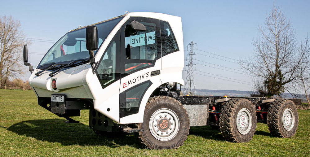
Six-pack muscle
(Courtesy of Poppy Jakes Photography via EMotive)
Peter Donaldson traces the development of this go-anywhere EV created to carry multi-tonne payloads
EMotive’s 12 t Scarab 6×6 electric off-road truck is designed to appeal to a range of industries including agriculture, forestry, quarrying, mining, adventure tourism and airfield firefighting – all areas where large zero-emissions vehicles are becoming increasingly attractive.
Managing director Dan Regan reports excitement about the vehicle from the agricultural industry in particular. “People in agriculture feel like they have been forgotten; a lot of innovation in the UK is supported by the government, but only in recent months have we started to see agriculture-themed Innovate UK projects in the spotlight,” he says. “However, in terms of commercial interest, airport fire tenders lead the way, largely in the Middle East where there is a lot of work around zero-emissions, zero-carbon cities, which will have airports.”
EMotive is also talking with an adventure tourism company in Iceland, an environmentally sensitive country with plenty of geothermal energy. “The Icelandic government loves the income from tourism, but doesn’t love big diesel buses, and they have a very clean way of charging EVs,” Regan notes.
As an idea, the Scarab had its genesis in the mind of inventor and entrepreneur Bruce Palmer as far back as 1999 when, long before founding the company, he began work on a prototype six-wheeled all-terrain vehicle intended for agricultural use. Wood and cardboard mock-ups led to a more substantial proof-of-concept vehicle dubbed the Mk1, which made use of Land Rover components, including the V8 petrol engine and driveline parts.
Working with this machine, Palmer learned a lot about suspension geometry and stability, particularly the balance between off-road ability and stability at speed on the road, Regan explains.
“He then started de-constructing this machine to build Prototype B, whose agility he experimented with, investigating axle travel and power distribution between the wheels, which was all mechanical at that stage,” he says. “That phase lasted until 2001, when he was confident that he’d come up with something that was scalable.”
“He then realised that it would take 6 or 7 years to get it into production and that the future of such vehicles would obviously be electric. Looking at the market for electric components, he found that it wasn’t ready, so he parked the project and waited for suitable components to become available in volume at the right price.”
By 2016, Regan continues, there were many small passenger cars available from major manufacturers, indicating that the time was right to move forward. Palmer then dusted off the project, created a company and approached a contractor in Dorset, southern England, that was doing a lot of design work for the UK’s Ministry of Defence, asking them to come up with a chassis design. “By 2019, they had come up with a good, robust design that could be manufactured in volume,” Regan says.
At that point, Palmer decided he needed an in-house development capability, and brought in electrical and control systems engineer Regan as MD. Regan brings experience of writing control software for power station gas turbine generators at UK company Centrax, and of managing, engineering and funding hybrid and electric powertrain design at Ashwoods Automotive, not far from Centrax, where he was also involved in the development of the innovative commercial vehicle telematics platform Lightfoot.
(Author’s photo)
Once on board, Regan began building the team that includes operations manager Josh Roles, chief design engineer Steve Eldridge and head of systems engineering Simon Williams.
Regan emphasises that the contractor’s design provided them with a sound basis for development. “We have made some major tweaks and modifications in the past few years, but the bones of what they designed are all still there,” he says. “From day one, it was built around the electric architecture; there would have been no point in taking what was a combustion-engined chassis and trying to shoehorn in an electric drivetrain.
“All the reports from Bruce’s early testing were provided to the contractor. They were given a brief on what the electric powertrain needed to do in terms of performance, and they designed the mechanicals around that using our specification, results from prototype tests and their own experience to create the current architecture.”
Driveline architecture
Williams spent 18 years with UK specialist military vehicle developer Supacat, including a period in charge of the electrification of the Jackal platform and several overseas deployments with military forces as a civilian contractor, gaining hands-on operational support and maintenance experience with end-users.
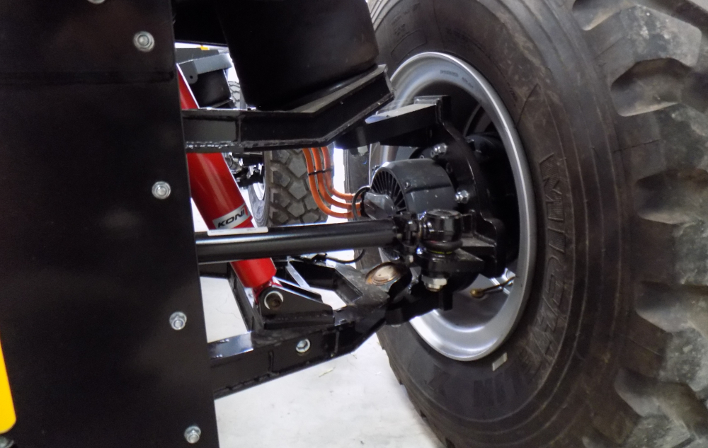
He explains that the driveline architecture is based on in-wheel propulsion, with, in the development prototype, a Dana electric motor coupled to a Lancereal reduction hub in each wheel. The modular design enables any number of axles up to six to be driven and/or steered.
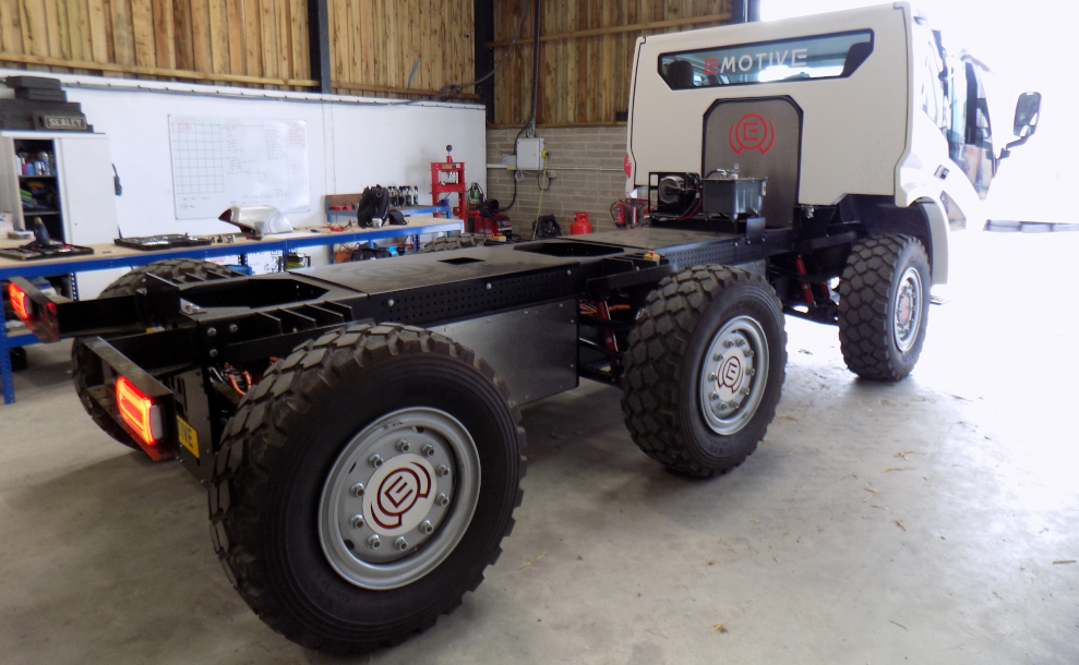
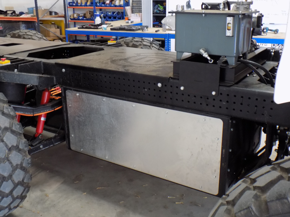
Feeding that propulsion system in the Scarab prototype is a Webasto battery pack in an enclosure attached under the chassis rails between the centre and rear axles. An identical enclosure between the centre and front axles is empty at the moment, but it could house a second battery pack or a range extender.
Williams says EMotive is keeping its options open here, and could install an IC engine-based generator with several fuel options, including hydrogen when H2 combustion engines become available (from around 2024, he reckons) or a fuel cell stack. The company is now looking at how much power it can get from an IC-engined generator that will fit the available space, he notes.
“Combining a battery and range extender opens up applications such as underground mining,” Regan adds. “We are speaking to one company that uses explosives to extract minerals and now has to have three vehicles: one road vehicle to bring the explosives to the site, changing to an overground off-road vehicle, then changing again to one that can be run safely underground. With the Scarab, they could travel to the site on roads using the range extender, then switch to battery power to go underground.”
(Author’s photo)
Chassis and suspension
With an emphasis on ease of manufacture at reasonable cost, the chassis structure consists of a pair of main rails that run from the front of the vehicle to the back, and are made from profile folded steel sections. They are connected by welded steel plates to form a ladder frame.
Underslung from these rails are the bolt-in axle assemblies, which consist of a central steel truss on which fabricated steel upper and lower wishbones are carried on bushed pivots. Each axle bears weight on a pair of air springs, one either side, the upper mounts for which are welded to the chassis rails, with each spring controlled by two Koni telescopic dampers.
“That gives us a large suspension travel,” Williams notes. “Ride comfort, stability, traction control and so on will all benefit from that.”
The air springs themselves are commercial truck units, which are well-proven, robust and even somewhat overspecified for the vehicle’s weight to provide a margin for running on more demanding surfaces.
“They will do the hard work of supporting the payload and withstanding the extreme impacts of shocks and bumps over harsher terrain,” Williams says. “The air springs will take out all of that, and the twin Koni dampers will take out the high frequencies.”
Each axle assembly forms a module, and with the disconnection of the air springs and a few electrical and fluid connections, the entire drive system can be unbolted and dropped out. “That’s good for maintenance, and also means it can be built on the production line as a sub-assembly and bolted in.”
At the moment, the Scarab prototype has front-wheel steering only, but the team is preparing to add a powered rack to the rear axle. “With modularity there’s nothing stopping us from having the same axle sets in all three stations,” Williams notes.
“You could have six-wheel steering for example, as in some applications it might be useful to crab the vehicle. The whole mindset is modularity and adaptability to perform many roles for many users.
“Air springs allow us to carry a large payload,” he adds. “One target was to keep kerb weight as low as reasonably possible.

“In doing so, we are keeping all the components low in the chassis, which then means we can carry a larger payload higher up and still keep the centre of gravity reasonable. We are targeting a kerb weight of between 4.5 and 5.5 t, depending on the type of range extender and fuel tank installed, allowing up to 5.5 t of payload.”
That adds up to 11 t, although the allowable maximum gross weight is 12 t, plus some margin for future-proofing. “As the platform is scalable, we can design components such as axles and wishbones that allow us to go up a little more again without starting from scratch.”
Together, the chassis and suspension provide strong support for the driveline. Williams explains that the team is in the process of working out how much power they can extract from the batteries, feed to the motors and translate into torque at the wheels to get the performance they want.
“We’ve done quite an in-depth study on different terrains, calculating and physically verifying rolling coefficients, then translating that into how much torque and power we need to climb up to 60% gradients in different terrains – on highway, grass, wet mud, sand, gravel and so on,” he says. “What that translates into is a target of 75 kW continuous power rating per wheel and a 150 kW peak, then with the ratios in our reduction hubs we will be up to 6000 Nm of torque per wheel.”
This, he says, covers the extremes of what the vehicle is likely to be asked to do in service, ranging from the most demanding end of the spectrum represented by a fully laden vehicle climbing 10-25% gradients in sandy conditions, to an airport fire tender that simply has to cross flat ground quickly at the other end.
“Fire tenders don’t need anywhere near that much torque, so you can fit just two driven axles or look at reducing the cost to the customer by changing to a less powerful motor.”
Regan notes that it is important to avoid closing off technical options so that they can retain versatility. “Wherever we have been able to offer different motor power ratings or reduction gear ratios, for example – something that doesn’t really add any cost but adds versatility – we’ve done that kind of thing all round the vehicle,” he says.
(Author’s photo)
“It means working with a supplier who can provide a substitute part with exactly the same form and fit but with a different function, such as a motor with a different type of winding or a reduction hub with a different number of teeth on the output. We want to make it an easy tick-box option.”
At the moment, the development vehicle is fitted with relatively low-powered motors and a 48 V primary electrical system, owing to the longer lead time for the higher performance parts that production examples will have.
“We wanted to get the vehicle performing, doing tests and trials to verify our calculations, which is what this interim system has allowed us to do,” Williams explains. “And we are now looking to integrate an 800 V system with high-power motors and associated driveline components.”
Regan adds, “We have a drivetrain in there that provides us with a fraction of our final torque for the production model, but it tests the steering, the suspension, the manoeuvrability and the braking systems. Getting a lower-spec driveline in there early has provided us with some valuable early learnings, and we are now waiting for components for that 800 V system to arrive.”
Motors and reduction hubs
The Dana motors in the development vehicle are radial flux machines that provide 1500 Nm per wheel, or a quarter of the 6000 Nm that the production vehicle will have. The Lancereal hubs through which these motors drive are two-stage planetary reduction gearboxes with a 29:1 overall reduction that gives a top speed of about 30 mph, Williams says. With torque at 1500 Nm, that translates into about 15-20 kW from each wheel motor.
In the production vehicle, the motors will be new; the reduction hubs might be as well, pending the results of an experiment that Williams has in mind. “I quite like the fail-fast approach, trying something to see if it works before committing a huge amount of time to a particular task,” Williams says.
“Depending on how our timeline is looking, we could use the existing hubs with a more powerful motor and accept that we won’t achieve our desired top speed – we were hoping for 62 mph – but we would get all the power and torque we need in the configuration that the vehicle is in now.”
He notes that one of the biggest challenges with the hubs is input speed, as many that are available are restricted to around 5000 rpm, and EMotive wants to run at higher speeds than that, probably between 8000 and 10,000 at the input. However, the motors being considered are of the axial flux type, whose ‘pancake’ proportions suit them well to in-wheel applications. Also, they are optimised for 15,000-16,000 rpm, although they can be limited to the desired speed by the inverters.
“We can achieve the power and torque requirements from a lower speed, which then simplifies our mechanical design for the epicyclic hub,” Williams says. EMotive is currently working with Lancereal on the specification for a new design of hub, should that prove necessary.
(Author’s photo)
As the motors are mounted in the wheel hubs, which are carried by the suspension’s upper and lower control arms (the wishbones), these wishbones have to handle the vehicle’s weight with a full payload and all the torque reaction loads up to the full 6000 Nm plus some safety margin, both when the motors are driving and when they are used for regenerative braking. What’s more, the back-up friction brakes are integral with the hub, adding to the loads that the wishbones must transmit, so they have to be very beefy components.
“We intend to perform extensive reliability and durability trials on the platform, so we will look to build a number of prototypes to iron out any faults that appear,” Williams explains.
The team has also been testing brake resistors, devices that consist of resistive heaters that are used to dissipate excess electrical energy from regenerative braking when the battery pack is fully charged and unable to accept any more. “We also needed to make sure the service brakes stop the vehicle effectively if we can’t get any regenerative braking, so we have also been testing them,” Williams notes.
“There will be a lot of later stage learnings,” Regan adds. “Much of our suspension testing so far has been at no load, and we haven’t had the Scarab loaded up to 12 t yet. We have fabricated wishbones at the moment, whereas later on we will have to do production-intent prototyping, which will be with cast wishbones, so there is still a long way to go in terms of learnings.”
Much of that knowledge will come in the next stage of development, Williams notes. “Whereas here it is big and bulky, we will go through a mass reduction exercise using a combination of physical testing and finite element analysis.
“We will start lightening the chassis so we can drive our kerb weight down, increase the payload and so on. When it comes into castings, yes we gain: we reduce mass and increase strength, and it’s cheaper to manufacture in volume, so it is definitely in our development plan. However, we are focusing more on the functionality of the vehicle right now, and the productionisation stage will follow that,” he says.
“We have kept ourselves on the straight and narrow through various iterations of finite element analysis [FEA] on the chassis, especially when we have been making modifications to the initial design,” Regan adds.
“In the final stages we will be going through everything with a fine-toothed comb in terms of FEA, working out if there are areas that we have to put in extra strengthening, perhaps changing a radius here and there on the chassis where we have laser-cut parts. There will certainly be some tidying up at the end.”
(Author’s photo)
Traction control and active suspension
As each airbag/spring can have its pressure increased and decreased individually by the electrically driven compressor, they form the basis of a kind of active suspension system that can be used for advanced functions including traction control, ride height adjustment and potentially ride levelling, all of which are currently in development or under consideration.
“At the moment we are looking at doing everything with a single ride height, although we can add an adjustment capability, Williams says. I don’t yet know whether we will go for a dynamic ride height or a passive system with on-road/off-road settings that the system would maintain regardless of load.”
He explains that the left and right sides of each axle could be linked pneumatically to manage body roll. “It is not something we are doing now, but there is no reason why we couldn’t with the systems we have on board. The master controller can easily look at wishbone angle to determine the ride height, and change the air pressure in the springs to adjust the height accordingly.”
The air suspension could also help maximise grip and traction, he says. If there is a loss of tractive effort from an individual wheel because it is slightly off the ground, the system can add pressure to that wheel’s air spring to push the wheel down for firmer contact with the ground. “This is all part of our thought process, and as we progress through the trials period we will go through that and see if we need it,” he says.
“Having individual motors, one per wheel, gives us good control of our traction. Using the master controller, we can monitor and control each wheel station individually and, when we detect a loss of traction we can change wheel speeds and apply braking where needed to restore it. With the adjustable pressure in the air suspension we can enhance that capability significantly.
“We can also determine axle loads through our airbag pressures, so we can calculate how much mass we have on each wheel station. We have encoders in the motors to show their rotational position, we have ABS sensors, and we have individual control of each motor and its service brake.”
“Although there is still a lot of work to be done on testing the traction control, we are giving the system all the sensors and feedback it needs to gain that full control over each wheel station. The master controller will know where each wheel is within its range of vertical travel and steering angle, how fast it is turning and in which direction, what the torque loading is and how much weight it is carrying.”
Detailed design and testing of the system is due in the next phase of the Scarab’s development, Williams adds.
“We are essentially building all the technology in at this level, not just for traction control but for future control options as well, such as autonomy,” he says. “The platform will have interfaces in the architecture that will allow an autonomous platform to sit above it. We want to make sure we hit the market with the latest technology.”
Battery packs and electrical architecture
Meanwhile, the company is working with Webasto on the battery system. This is based on the latter’s commercial vehicle CV Standard Pack, which features lithium-ion prismatic cells using nickel-rich NMC chemistry and comes in 35 kWh modules that can be connected to form larger packs, either in series or parallel depending on the required voltage and capacity.
“We would look to have a number of those batteries as standard, and then we can multiply them up to 175 kWh in total,” Williams says. “You can get a huge amount of power out of them as well: we looked at supercapacitors, thinking that in some applications we might need a large peak of power, but the batteries will provide it on their own.”
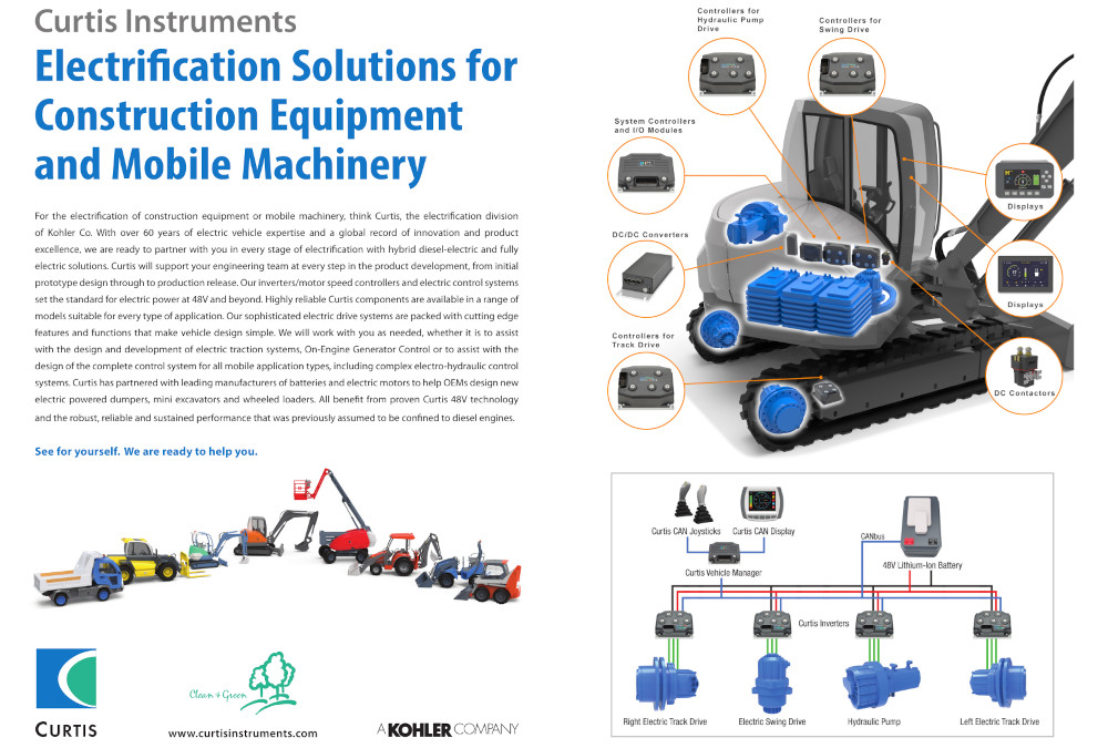
Between the battery and the motors is a multiple inverter system, with an inverter per motor for a total of six. They are all supplied by Curtis Instruments, fed by a power distribution module and managed by a master controller through a CAN bus. “The master controller is the brains of the vehicle and will control all the tractive effort through algorithms, as well as interfacing with the battery management system,” Williams explains.
Changing to a high-voltage electrical system will also require a new inverter system, and Williams describes the one that has been selected as a very high power specification inverter that is well-suited to off-highway applications.
Smart power distribution
EMotive is also designing its own HV power distribution interface module. This will draw power from the battery packs and deliver it to the motors via the inverter, as well as to various electric power take-offs for accessories and payload systems. It will also send power from the onboard generator/range extender into the battery packs to top up their charge.
“The power distribution module is just a way of managing the power in a way that maximises the amount we can handle,” Williams notes. Off-the-shelf systems are very limited as to how many kilowatts we can put into them from onboard generators and so on, so we are looking to develop our own solution.”
In terms of componentry, the interface module will consist essentially of a set of HV, high-current contactors run by the master controller in concert with the battery management system, he explains.
The low-voltage system also features intelligent power distribution in the form of a solid-state module from ETA Energy Technology that integrates semiconductor switches with power management capability. The switches are MOSFETs, each of which functions as a relay and a circuit breaker/fuse.
“We don’t have a conventional standard bank of fuses and relays; their functions are all handled by the MOSFETs and software fusing, which is very configurable,” Williams explains. “It’s an intelligent module in its own right. No more flash relays; it’s all done on timed circuits.”
The module is much more controllable than conventional fuses and relays, Williams says, and allows systems engineers to set any thresholds they need for the fusing. “You can change the inrush currents, for example. It’s all part of the more intelligent system architecture that we’re going for really, with an eye to future-proofing.”
Regan notes, “It also means that when a circuit blows we will pick it up via our telemetry. And we can then talk to the driver, investigate what is going on and even remotely reset it.”
In addition to the solid-state power electronics, there are also computer chips and comms hardware in the module that enable its data to be uploaded to the cloud.
Also, the power management architecture will include a separate DC-DC converter that will take in 800 V DC and supply 24 V DC to open and close the battery pack’s HV contactors and to power the vehicle’s lights and other standard automotive ancillaries. The final major HV device will be a DC onboard charger capable of delivering 22 kW to the battery.
“We are designing in suitable components to meet our high power demands,” Williams says. “With an off-road vehicle, we have not just great extremes in terms of how much power we need, there are many variables as well in between, whereas on-highway applications have fairly straightforward duty cycles, perhaps from a depot to a site and back.
“We have so many applications that we have a very diverse set of drive cycles, so the challenge has been to find equipment that will allow the vehicle to do all of those things. We have selected our componentry and we are integrating now, hoping to physically fit them within 10 to 12 weeks.”
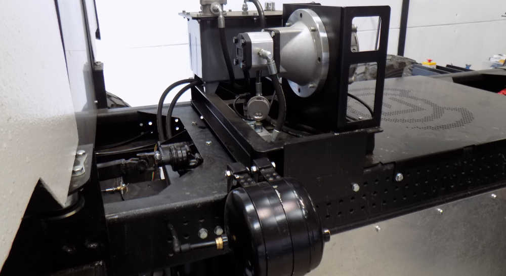
At the moment, the vehicle is fitted with an electrically driven hydraulic pump for the steering, and a compressor for the truck-type air brakes, which are held off against spring loading with air pressure, both of which are currently low-voltage devices but will be replaced by 800 V items in the next iteration of the system design, Williams says.
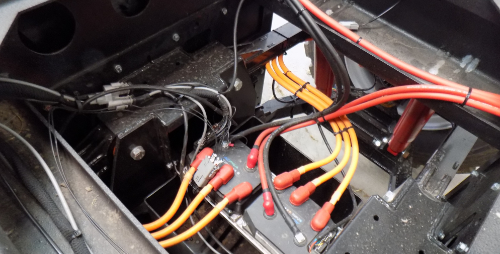
The wiring in the Scarab development vehicle as it stands now includes red 48 V cabling connecting the battery pack to the inverters and orange cabling that links the inverters with the motors. While the orange cables don’t yet carry high voltages, they do carry AC and are screened so that they don’t cause EMI with other systems. They are also ready to handle HV power, so they won’t have to be changed, Williams notes.
(Author’s photo)
Electrical safely
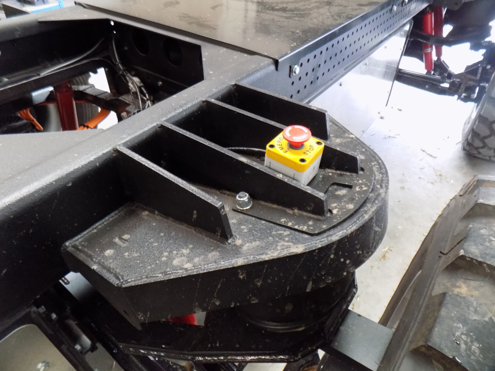
As a development prototype EV, the Scarab has multiple emergency stop buttons, including one in the cab, one inboard of each wheel on the centre axle module and one behind the rear axle module.
The 800 V system is designed to comply with the tougher legislation that applies to such HV circuits. “We will be integrating all the service disconnects and crash inertia switches that open the main contactors internal to the battery pack, and there are pre-charge circuits in the battery pack as well,” Williams says.
Any HV system containing capacitors or components with capacitance can be damaged by inrush current when first switched on, and contactors can even be welded closed by the heat generated, so pre-charge circuits containing resistors are used to limit the inrush current while the downstream capacitance charges up.
The system also features HV interlock loop (HVIL) wiring that carries the low-voltage power supply to operate the HV contactors in the battery pack. Normally incorporated into all the HV connectors, the HVIL ensures that every HV component is securely connected to the battery before the main contactors can close to energise the HV system. The HVIL wires also run alongside the HV cables so that any damage to them is likely to cut the power and open the contactors.
The HVIL is used with an isolation monitoring system that will open the main contactors if the isolation between either side of the HV system and the chassis falls below a preset value, which would be a symptom of a short-circuit.
(Author’s photo)
Williams emphasises that the HV system the company is developing for the Scarab will comply with all these galvanic isolation and other safety regulations. In addition to the main contactors in the battery, the secondary contactors in EMotive’s power distribution unit will also open in response to such faults, and there is further redundancy in key control circuits.
“There are a lot of people out there using this kind of vehicle, certainly maintainers, who may not have seen such high-voltage systems before. We will have to comply with legislation, but in terms of practicality we are designing it with both safety and maintainability in mind, which is important for end-users who have to train their technicians.”
While the Webasto battery pack has its own compliant safety features built in, they have to work seamlessly with the related devices that EMotive is integrating into the vehicle, including the crash inertia switches, emergency stop buttons, service disconnects and so on. As is always the case when integrating subsystems and components from different suppliers and others developed in-house, it is vital to define exactly where these parts meet in an interface control document, as Williams explains.
“That is a bit of a tiring exercise that I have been going through for a number of months now, finding out where those interfaces are and what they require in terms of inputs and outputs, and what we can then do with their controls,” he says. “Webasto have been great with technical support, doing everything they can to help us.”
Staying cool
Thermal management is another area in which EMotive is working with Webasto, which is helping to optimise the system for different customers and applications, and helping to determine what each user needs in their particular operating environment.
“What we don’t want to do is throw everything at it and give them a really expensive system that just isn’t needed,” Williams says. “We can harvest small amounts of power that would otherwise be wasted by the motors, the battery or the inverters and pump it back into the cab environment.”
He explains that with a small cab seating three people, and operating in a temperate environment, only a modest amount of heating and cooling capacity is needed, while an adventure tourism vehicle with a cabin that holds 20 people will have much more demanding thermal management requirements.
“Again, modularity will enable the vehicle to perform quite happily, for the sake of argument, from – 10 C to + 35 C with a standard system, but if it is going into an application where there will be extreme cold or extreme heat then we would fit extra components to suit,” he says.
The baseline system from Webasto provides thermal management for the battery, the motors and the cabin. It features a heat exchanger that can transfer energy between the water/antifreeze loop and the refrigerant loop while allowing extra modules to be added to tailor the capacity to each application.
“Giving the customer the ability to specify the vehicle to meet their budget is one of the biggest wins when it comes to making it affordable,” says Williams. “A key focus of ours is to get the bill of materials to a very competitive level.”
Refining maintainability
Eliminating the IC engine, gearbox, transfer cases, propshafts, differentials and half-shafts means they are not there to break or wear out, and it also frees up a lot of volume under the chassis and consequently eases access to the other components. Williams points out, however, that it remains essential during the design process to review each component periodically for maintainability, characterising this as one of the biggest exercises the engineering team has to undertake.
“It really starts with considering where the vehicle is going to be maintained, who is going to be maintaining it and what sort of tools they will have, and then designing relevant parts of the system to suit that,” he says. “Clearly, there are different tiers of maintainability and tasks that are likely to be carried out at the roadside or in the field with limited tools at a local depot or a fully equipped maintenance base. At its simplest, if you must access a bolt to remove a component, can you get a spanner on it?”

(Author’s photo)
Looking at the vehicle as it is now, without a body on the chassis (other than the cab), most of the working parts are easily visible, from the motors and hubs in the wheels to the suspension arms, the suspension air springs and dampers and the inverters, all with clear space around them.
In terms of electrical components though, there is still some work to be done, Williams notes. Here, maintenance access will have to be balanced against keeping parts out of harm’s way by, for example, ensuring they won’t snag on obstacles over which the vehicle passes. One of the biggest jobs, he notes, is re-routing the cables from the inboard-mounted inverters to the wheel motors through the centre of the suspension articulation.
“We are coming up with a solution that will allow the cabling and all the other services such as hydraulic hoses and cooling pipes to sit centrally and move in relation to the wishbones so that they are all suspended and supported,” he says.
“We have a protective casing for them as well, and routing them centrally allows us to accommodate the full articulation of the suspension and, if a customer chooses a steering axle, we won’t have wires biased to one side.”
As operations manager, Josh Roles is responsible for procurement, working with suppliers to make sure the right materials and components arrive when they are needed and generally making the project run on time. He also overseas construction of the prototype.
He cut his technical teeth as a helicopter engineer in the Royal Navy before moving to McLaren, building engines for GT3 cars before joining the Formula One team as a travelling mechanic. A stint at Ashwoods Automotive followed, where he headed up prototype and vehicle integration for the company’s conversion of excavators and trucks to electric power, joining EMotive after Ashwoods was bought by Dana.
Joining the project when the development prototype was little more than a chassis with a cab provided an opportunity to focus on making build and assembly processes easier and optimising access for maintenance, drawing on his experience in Formula One where none of these things are easy and lessons on what to avoid are plentiful.
This experience should be useful when replicating the front-wheel steering system on the rear axle. “There are a few bits we need to take into consideration, for instance articulation around the phase cables, routing of coolant pipes for the new liquid-cooled motors,” he says.
“It’s not too much of a challenge though, because we are already running cables to the motors, but because it’s an off-road vehicle it has to be in a way that ensures it will not be damaged. It won’t be open to the elements because we will put it through some kind of casing.
Hopefully, that is where my experience will pay off because nothing is exposed in Formula One cars, everything being routed through conduit and through wishbone shrouds. This is a very different vehicle of course, but we can apply the same principles in a way that prolongs component life and reduces the risk of exposure that could cause component failures. Formula One cars are notorious for being hard to maintain.
“It is not easy to just pop a brake line out of a rear axle or a rear corner, because it is all integrated into the wishbone, so you have to strip the wishbone to get to it. That is what we want to avoid, but we are lucky in that this is nothing like as intricate.”
Also to ease maintenance, all the service connections to the hub motors use dry breaks to prevent leakage from any of the systems if they have to be disconnected if for example an axle module needs to be changed. “That minimises downtime, which is of the utmost importance for the applications that we are looking at,” Roles says.
The suspension uses bushes and ball joints, which as in any vehicle are subject to wear and tear, but there are no grease nipples or other lubrication points.
In the development vehicle, the battery pack is installed and removed from the top of its compartment, which EMotive intends to change. In the production version, the pack will be accessed from the side using a forklift, a telehandler or a pallet truck, or a tool adapted to fit a standard piece of agricultural equipment, for example.
The company also plans to offer a battery swap-out capability, but there are challenges associated with that including the cost to the end-user of having two batteries, access to handling equipment, a charging system for the second battery and so on.
Licensing manufacture
When development of the platform is complete, EMotive intends to license the design for local manufacture around the world rather than building them in volume itself. “With these specialist applications, people tend to be loyal to a brand they trust and which provides good aftersales support, so we want to work with established brands,” Regan says.
Key specifications
Scarab off-road truck
Maximum gross weight: 12 t
Kerb weight: 4.5-5 t
Payload: up to 5.5 t
Drive system: 6×6 with in-wheel motors and two-stage reduction hubs
Maximum wheel torque: 6000 Nm
Power: target of 75 kW per wheel continuous, 150 kW per wheel peak
Maximum speed: 30 mph (62 mph projected)
Battery capacity: 35-175 kWh depending on number of battery packs
Voltage: 48 V for development vehicle, 800 V for production
Some key suppliers
Steel fabrication: Atom Fabs
Steel fabrication: Luffman Engineering
Inverters: Curtis Instruments
Motors: Dana
Fusing, relays and power management: ETA Energy Technology
Dampers: Koni
Reduction hubs: Lancereal
Battery packs: Webasto
ONLINE PARTNERS

