


EMI

(Courtesy of KIST)
Interference fits
Nick Flaherty explains the different ways of protecting against EMI in EV platforms, and why it needs to be considered from the earliest stages of system design.
Essentially there are only three ways to handle electromagnetic interference (EMI) – don’t produce it, filter it out or shield from it. These options lead to a wide range of design trade-offs in e-mobility designs, from the power systems through the interconnect and cables to the vehicle’s overall weight. The challenges of EMI are increasing as well, as designs using wideband-gap semiconductors that switch at much higher frequencies than before become more widespread.
Whereas power conversion systems with silicon IGBT power devices typically operate at 20-100 kHz, wideband devices based on silicon carbide can switch at up to 1 MHz, and gallium nitride devices at up to 4 MHz. However, the latter two create more harmonics up into key frequency bands at 2.4 and 5 GHz, which might interfere with radio systems and other devices in vehicles.
Wireless battery management systems (BMSs) are being developed that operate at 2.4 GHz, and EMI from the inverter system and other wireless technologies such as Bluetooth and cellular phones could be a significant safety risk by interfering with the transmission of battery data. These systems are being designed to be robust and to protect against EMI, but there are still currents and voltages induced in other parts of the system – in the electronics, cables and interconnect – that have to be filtered out or shielded.
Designing to minimise EMI
All emitting subsystems have to meet maximum EMI emissions such as CISPR25, CISPR12 and SAE J551-5 to meet safety regulations, so minimising emissions in the first place avoids the need for additional filters and shielding that add weight and cost to a design; making systems less susceptible to EMI in the first place also helps. The standards are evolving though, so a design from a few years ago that previously passed might no longer be suitable.
The high-voltage parts of an EV are the main sources of the electrical noise that causes EMI in the rest of the system. Alongside the inverter and the battery pack, which can be operating at 400 or 800 V, there is also the DCDC converter, the onboard charger, the power distribution unit and all the connecting cables.
One approach is to look at new topologies such as zero-voltage switching. As the name suggests, this switches when the voltage is at zero and so minimises the current flow causing the emissions. Adding power factor correction can also reduce the overall EMI emissions.
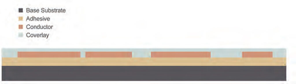
The structure of a flexible circuit for a wiring harness
(Courtesy of Trackwise Designs)
The switching currents generated can use the copper interconnections as antennas to emit EMI. This can be avoided by keeping the interconnect lines short and using multiple layers in a printed circuit board (PCB). Using short lines to connect to another layer or a ground plane reduces the EMI dramatically compared with long copper connections.
Using spilt ground planes that are on the same layer of the board but not connected together, except by the ground link, can also avoid variations in the electric field that cause current to flow and EMI to be generated.
While multiple layers and split ground planes can increase the cost of a PCB compared with a simple single-layer board, reducing the EMI can reduce the need for filters and shielding in the rest of the system. Similarly, a shielded connector can be more expensive than a non-shielded version but can reduce the cost of EMI testing.
Differential lines can also help to remove EMI. This uses two conductors to carry the same signal, so any noise that is picked up can easily be rejected using a simple common-mode noise filter. Whether it’s a pair of cables twisted together or two lines on a flexible circuit board, however, there is additional cost.
Using flexible circuit boards rather than cables for a wiring harness also gives more controllability. The conductors on the boards are smaller and lighter than cables, and are always in the same place with respect to each other. Cables, on the other hand, can move around slightly, changing their electrical relationship and making the common-mode noise rejection more complex.
This highlights how EMI reduction is a system-wide issue.
Filtering
For filtering, three things need to be identified: the source, the transmission and the ‘victim’. In an e-mobility design the source of noise is in the power converter or motor, the transmission is usually the wiring harness (which can have up to 1 m of antenna) and the victim is an electronic control unit (ECU).
If limiting the source with good design doesn’t work, the next step is to filter the source. If that doesn’t work then filtering the victim is necessary. Filtering cuts out particular frequency bands where the EMI shows up. This can be implemented using a filter that consists of an inductor and capacitor (LC) network.
For an LC network in an automotive design, the key challenge is the capacitor. Film capacitors have a limited lifetime, and are constrained by the temperatures and voltages they can tolerate, but the main limitation is the safety standard. This says the capacitor cannot store more than 0.2 J of energy, which limits the total capacitance to 800 nF.
Designers therefore have to decide how much of that is allocated to the motor, battery and power distribution unit. This leaves little capacitance for any filters.
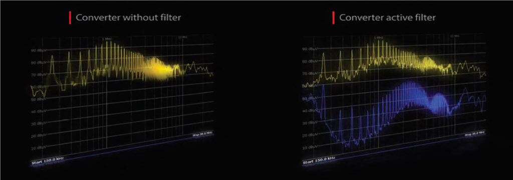
Active filtering
There are two types of filtering: passive and active. Active filtering measures the interference across the entire band and generates a signal that is the exact opposite. That cancels out the interference without the need for multiple filters or suppression beads. However this relies on complex, highspeed signal processing.
The big difference in automotive designs compared with other power or motor designs is a focus on cost reduction, design for manufacture and quality, and meeting strict loading conditions for power, voltage and thermal requirements of between -40 and +125 C.
Active filtering is already used for acoustic noise cancelling, so the principles are well-established. The difference here though is that the EMI frequencies are much higher than for sound.
The active approach works with a sensor taking the EMI noise, identifying specific frequencies, generating a signal of equal amplitude and opposite phase and injecting it back into the network. However, a purely active system is not yet practical for cost reasons, so a hybrid of active and passive has been developed.
The passive filter cuts out certain bands, allowing the active filter to operate on low-amplitude noise, making it simpler and more cost effective.
One implementation uses a passive filter at 2-3 MHz to remove the highest frequencies, then the active filter operates from 10 kHz to 2 MHz and 3-4 MHz. It is possible to go to higher frequencies with the active filter but there is a trade-off between size and cost. Both the passive and active elements of the filter must also be finetuned for every specific inverter system.
In this way the design of a hybrid system is matched to the inverter. If the passive filter is not well-designed, the EMI is not filtered out and there is resonance caused by amplification of the noise. If the active element is not well-designed either, the electronics becomes saturated with noise and ends up injecting a full spectrum of harmonics into the system, making the EMI even worse.
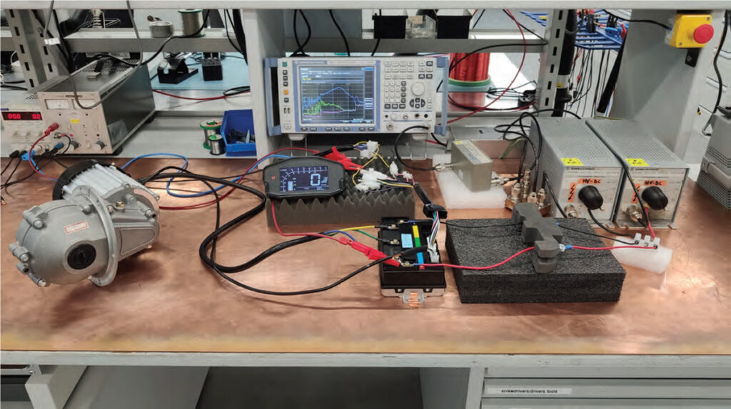
The test set-up for an active filter
(Courtesy of Schaffner)
The active part of the hybrid filter also needs to be fast, with a feedback loop from the initial input to the output that is within the sample time of the sensor, whether it be a current or voltage sensor, in order to compensate accurately for the noise. This feedback time depends on the impedance the filter sees. The magnitude and the phase of the feedback also need to be highly linear in the frequency range of interest.
Generating the compensating current or voltage requires a high-performance amplifier with a driver stage and signal conditioning to drive the power stage. To generate a current requires a current source with very high source impedance, which is not straightforward to design across the frequency band of interest, as the current can be several amps in a few hundred nanoseconds. The active filter then injects the voltage or current using capacitive or inductive coupling.
A phase delay creates instability, so the sensor must be highly accurate.
The main challenge is in the source, generating a voltage or current with very specific characteristics. An active filter for an 800 V inverter system, for example, uses around 20 nF of capacitance, which is well within the total capacitance of 220-440 nF per line, but the choice of capacitance is important.
Under varying DC loading a ceramic capacitor changes its value, which can change the band it suppresses and therefore not suppress EMI noise in the system. The other problem is the failure mode. A film capacitor fails safely, while a ceramic capacitor can sometimes short. An active filter reduces the size of the film capacitor required by more than half compared with a passive filter but increases the cost.
Passive filtering
Depending on the system, there are different passive approaches to filtering out EMI.
A common-mode choke on the signal lines is very important, especially in the power lines where noise is generated. They have to handle up to 6 A, and have a small case, the size of a grain of rice (the 1608 standard footprint measures 1.6 x 0.8 mm). Reducing the size of these chokes using multi-layer ceramic technology for a surface mount manufacturing process is essential to reducing the overall size and complexity of the design.
(Courtesy of Schaffner)
The type of passive filter used depends on the placement of the ECU and the signal line. Many lines suffer from noise coming from harmonics from Bluetooth wireless comms, at 2.4 GHz, which is relatively easy to filter out.
EMI suppression is more likely to be achieved using a ferrite bead that is tuned during manufacturing to suppress a particular part of the spectrum.
However, using a suppression bead reduces the performance of the signal line and the bandwidth possible on it, as the bead tends to suppress a broad band. A bead with a tighter suppression band avoids interfering too much with signal lines, but then several beads with different bands are needed to suppress all the EMI. That can increase the cost and weight of the system, so developers have increasingly been looking at active filtering.
Noise on the powerlines is mainly wideband noise at around 1 MHz, so designers cannot specify one frequency. Ferrite beads are therefore a very good fit, as they have a wide range of impedance characteristics to target particular bands.
The latest surface mount ‘chip’ ferrite beads constructed in a 1608 package for automotive applications use a new internal electrode design that reduces the DC series resistance while raising the impedance of the bead, from 30 Ω to 1000 Ω at 100 MHz and 85 C. These can handle a rated current of 1.2 to 6 A.
More power consumption is often related to rising temperature, which has an impact on the effectiveness of ferrite beads. As ECUs become smaller and higher performing system-on-chip devices running at higher temperatures, the impedance of the beads can tail off, reducing their effectiveness.
The beads currently operate up to 125 C, but developments are aiming to support temperatures up to 150 C. This not only has an impact on the materials used in the multi-layer bead but on the reliability of the PCB for the solder and the thermal expansion. This is a key issue for AECQ qualification for automotive components as well.
Perhaps surprisingly, the powertrain is not so sensitive to temperature. That is because the battery pack has to be maintained at a temperature below 60 C, so there is a lot of cooling. This means filters for the BMS, for example, are less temperature sensitive.
Other filters are wire-wound inductors usually used for higher power lines in a DC-DC converter or onboard charger, as well as Ethernet signal lines in electronic control units, where temperature is also a potential issue. These are more square than the multi-layer ceramic bead versions – a factor that might have to be taken into account during the design – and are more often used to filter EMI noise on Ethernet cables around a vehicle.
For example, a typical wire-wound 80 V inductor in a 1210 package measuring 3.2 x 2.5 mm can operate over a temperature range of -55 to +150 C. This has been achieved by using a metal termination that absorbs the stresses associated with temperature change, as well as optimising the materials.
Shielding
The challenge with using a shielding approach to protect against EMI is that, for it to be effective, a subsystem needs to be completely covered in conducting material. Radio waves can escape through small holes, vents or around connectors.
Materials for shielding have progressed dramatically in recent years. The development of conducting 2D materials such as graphene and molybdenum disulphide, which are only a few atoms thick but still provide an electrically conducting coating for subsystems, deliver very lightweight shielding.
One example is a technique to fabricate an ultra-thin EMI shielding material using a new 2D material called MXene. The technique, developed in South Korea, is a combination of titanium and carbon, and has the same conductivity – about 10,000 S/cm2 – as metals.
The technique uses a volatile solution on the surface of a diluted MXene solution that induces floating MXene flakes. The flakes self-assemble into an MXene film that is up to 55 nm thick and provides 99% electromagnetic shielding efficiency. The film can be easily transferred onto equipment in a production process.
Replacing some of the carbon with nitrogen, to create titanium carbonitride, creates a variant of MXene that changes the way the shielding is applied. It absorbs radio waves rather than reflecting them, and can be sprayed onto components and boards rather than the subsystem casing to provide the shielding
EMI and pacemakers
One of the worries about EMI from the new generation of EVs has been the effect of the higher power of the radio waves on sensitive medical equipment, notably pacemakers. While interference with pacemakers can be rare, the consequences can be deadly – patients with one often worry about triggering interference when using appliances such as dishwashers, washing machines and metal detectors.
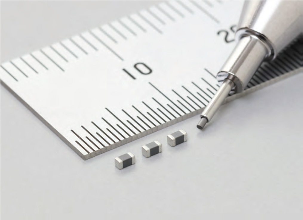
The latest ferrite bead for suppressing EMI noise
(Courtesy of Murata)
Pacemaker manufacturers recommend that patients maintain a distance of at least 30 cm from engine ignition systems and electric boat motors. However, the powertrains of electric cars have outputs far larger than average ignition systems – at up to 400 kW compared with 1-2 kW – and there are no specific recommendations for electric car use.
The potential for EMI increases with the strength of the electromagnetic field, which is proportional to the power of the electric motor. One study in Munich, Germany, in 2019 evaluated the performance of most of the pacemakers on the market in four of the leading battery EVs.
The tests showed that neither adverse events nor electromagnetic interference were detected while driving or charging the cars. The researchers conducting the tests put this down to the shielding used to protect the onboard computer systems from EMI during driving. The strongest EMI was detected when the vehicles were being charged.
Bearings
EMI can also have an impact on nonelectrical, metallic parts of a vehicle, such as the motor’s bearings. The bearings can be damaged by the effects of EMI caused by common-mode voltage arising from the non-sinusoidal waveforms produced by an inverter’s power-switching circuitry. The fast voltage rise times in the inverter can cause charges to build up on the motor shaft through capacitive coupling.
If this build-up is not addressed it discharges through the bearings, causing what is called electrical discharge machining. This erodes the bearings and leads to premature failure of the motor. At the typical motor speeds of 1000 to 16,000 rpm, shaft voltage discharges of 5 to 40 V or more are common.
These discharges create tiny pits called fusion craters in the steel surface. At inverter frequencies of more than 12 kHz, millions of pits can be created in a very short time. The process also creates steel and carbon particles that contaminate the grease on the bearing.
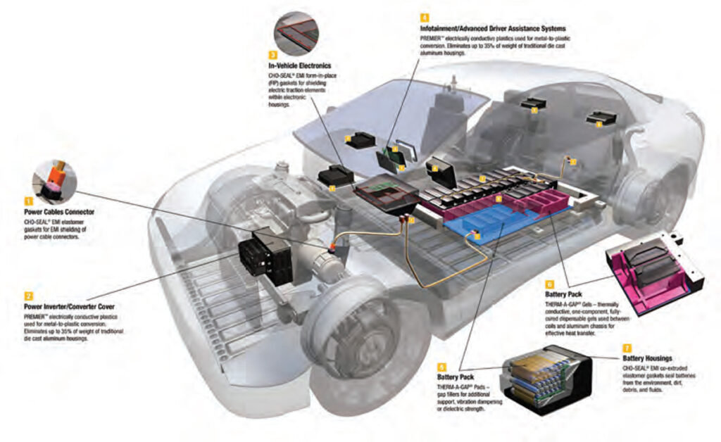
There are many places in an EV where shielding is needed to help suppress EMI
(Courtesy of Parker Chomerics_)
A phenomenon called fluting creates concentrated pitting at regular intervals along the bearing wall. This happens when the discharges occur in a regular pattern, forming ridges that in turn create noise and vibration.
The build-up of charge can be alleviated by spring-pressure grounding brushes made of graphite or metal. These can corrode, however, becoming clogged with debris and requiring regular maintenance. The drag from these brushes can also slow down the rotation of the shaft, so the motor has to draw more current from the battery pack, reducing efficiency.
Another approach to avoiding the build-up of charge on a bearing or shaft involves using a shaft grounding ring. This has conductive microfibres arranged along the inner circumference of the ring to surround the motor shaft.
The fibres can flex without breaking, to accommodate motor speeds of up to 16,000 rpm, with a surface wear of less than 0.001 in per 10,000 hours of continuous operation and no fibre breakage after 2 million reversals of motor direction.
Design tools
Given that there are many different ways to protect against EMI, so there are many different design tools. Some can look across all the subsystems in an EV to assess their outputs and the effect they have on each other.
One tool, developed in China, breaks an EV down into multiple subsystems and turns electromagnetic coupling paths into network parameters. That allows each part to be modelled separately using different technologies, allowing the overall vehicle-level EMI to be predicted during the design phase. The tool can handle calculations of EMI from 150 kHz up to 30 MHz
Other tools, usually from a specific vendor, help to specify ferrite beads, common-mode chokes and inductors for signal lines.

Conclusion
EMI permeates an entire electric e-mobility platform design, from the powertrain through the electronic control units to the bearings in the motors. It can – and should – be addressed from the very start of a design, using topologies that reduce the high-speed currents that produce the unwanted radiation.
Consideration of the architectures used in DC-DC converters, onboard chargers and power distribution units can minimise the radiation in the first place. Design tools can show how EMI from one area impacts on others, allowing developers to focus on the most vulnerable subsystems.
Using active and passive filters across the different electronic units can reduce the impact of EMI on more sensitive equipment, to avoid any compromise in performance. Care has to be taken though with the rising temperature of ECUs and its impact on components such as ferrite beads.
Then there are materials that can further mitigate the impact of EMI. Flexible circuit boards can reduce the weight of the wiring harness at the same time as protecting the signals against EMI. The lighter weight and smaller size also allows more signal lines to further mitigate the effects.
New 2D materials can be used to coat both the casings and components in ECUs to further protect them from EMI in the system, or to protect the bearings from damage from the build up of charge.
Acknowledgements
The author would like to thank Akihiro Ohno and Uwe Mirschberger at Murata, Allesandro Amaducci at Schaffner Automotive, Philip Johnson at Trackwise Designs, Koo Chong-Min at the Materials Architecturing Research Center in the Korea Institute of Science and Technology (KIST), and Cunxue Wu at the School of Automotive Engineering in Chongqing University for their help with researching this article.
ONLINE PARTNERS
