")


")


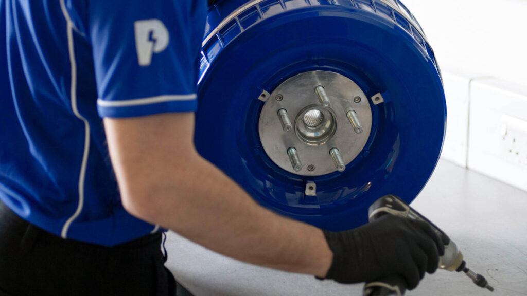
Protean Electric PD18 in-wheel motor
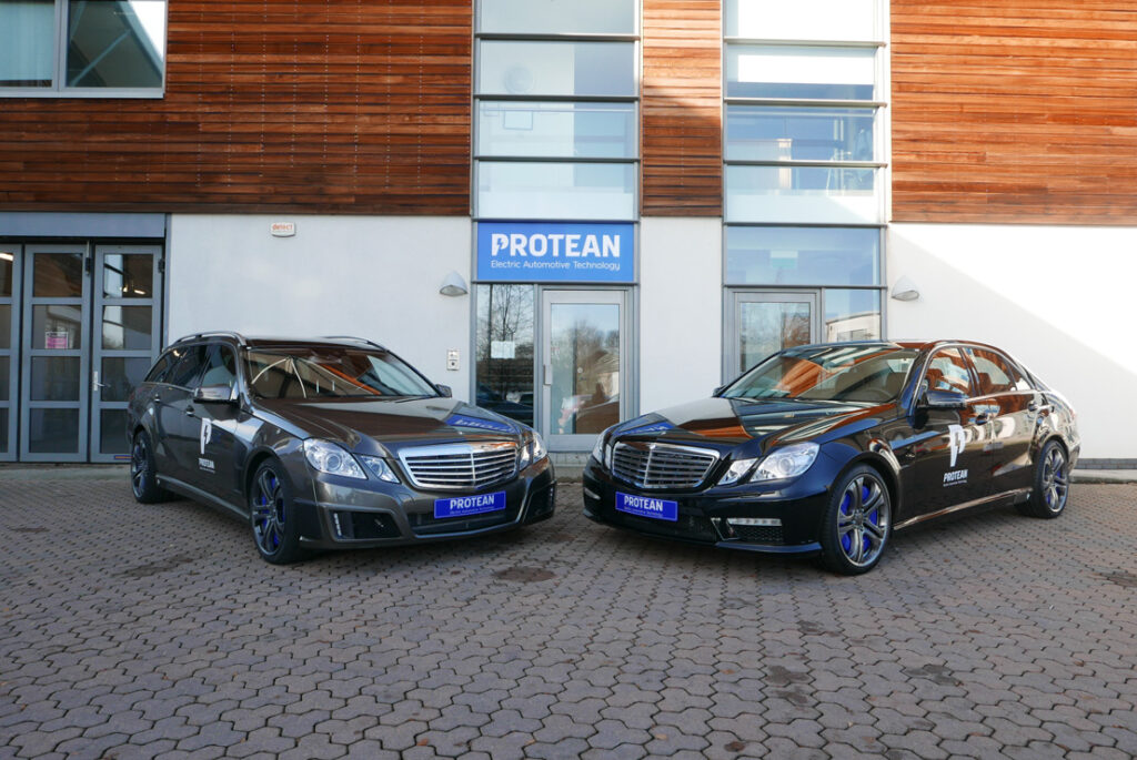
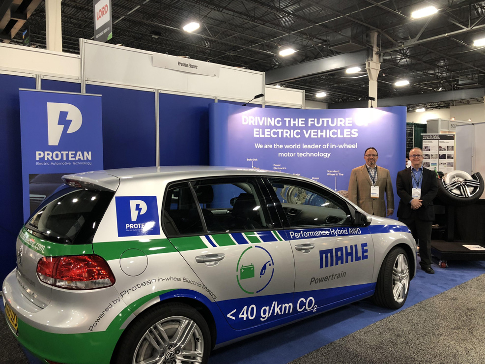
Just two of more than 30 vehicle models in which the PD18 has been demonstrated
Protean’s PD18 has a crucial advantage over other in-wheel motors – it can be retrofitted to existing vehicles. Wayne Ward reports.
Fit for the future
Pure electric vehicles are rapidly changing from being a niche purchase to one that will soon become commonplace. With the imperative that legislation places on the car manufacturers to reduce emissions comes a need to select a technology around which these vehicles will be designed.
Despite hybrids having been available from mainstream manufacturers for more than 20 years, this is a relatively immature sector from a technical point of view, if one judges maturity by convergence around a single, successful solution to passenger car propulsion that does not rely solely on an IC engine. In terms of converging on a single or small number of technologies that prove to be the most efficient, the most economical and which are reliable and safe, this journey is still very much only part way through.
So far, a common factor among carmakers entering the fray with hybrids or EVs is that the electric machines have been chassis-mounted, with the drive taken along conventional driveshafts to the driven wheels. That is understandable to some extent – early development can be done with some pretty conventional motors, and much of the existing vehicle hardware can be retained.
However, the packaging is not great. The motors, gearboxes and power electronics take up room on the chassis that might be put to better use, specifically for extra batteries. With ‘range anxiety’ being one of the major concerns among those purchasers still clinging to their IC engines, putting more batteries where the centrally mounted motors are might help here.

Step forward Protean Electric, a company set on another path, namely putting motors in the dead space currently occupied by the brakes on a conventional vehicle, leaving the centre of the chassis free for other components (batteries, capacitors or fuel cells for example). While Protean is not the only company looking at using in-wheel motors, its products have a key advantage: in many cases they can be retrofitted to existing vehicles, providing that the wheels are large enough in diameter.
The space on the chassis where an electric motor and transmission would normally be fitted can then be devoted to other functions. For full electric conversions, the chassis will not have to cope with the many and various demands that IC engines and ancillary systems place on it. A primary driver of chassis design will be how to package the maximum amount of energy storage systems safely and efficiently on the vehicle.
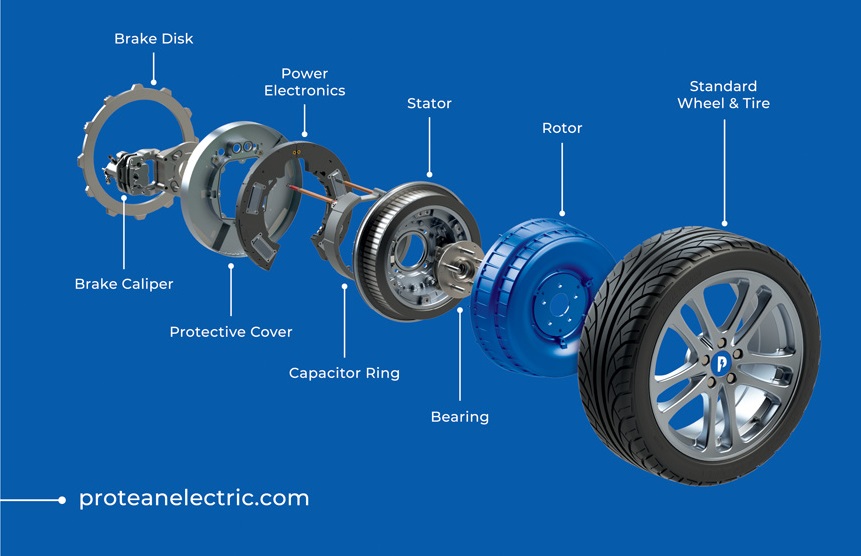
The Protean PD18 motor is unlike most of the electric traction motors that we are familiar with. The most obvious difference between a wheel motor and a conventional traction motor is the relationship between the rotor and the stator.
In a conventional motor, the stator surrounds the rotor, but in a wheel motor this relationship is reversed – that is, the stator is surrounded by the rotor. The Protean motor, in keeping with its design ethos of being a real retrofit, incorporates a disc brake developed in conjunction with UK-based brake specialist Alcon. The motor also incorporates all the power electronics, so the only connections required are for the high-voltage cables from the battery, the cooling circuits connections and the control systems wiring for the vehicle control unit.
The PD18 is already well-developed and has been successfully deployed in a number of technology demonstration vehicles, from small family hatchbacks such as the VW Golf, through the Mercedes E-Class and the Ford F150 pick-up to Vauxhall/Opel Vivaro vans. There have also been two- as well as four-wheel-drive applications, and pure EV and plug-in hybrid demonstrators.
The simplification aspect of using wheel motors is not to be underestimated. With hybrids still enjoying popularity, chassis are being developed that are required to mount engines, hydrocarbon fuel tanks, and large cooling systems for water and oil, in addition to traction motors, power electronics and (where applicable) gearboxes for the traction motors.
In the future though, with the envisaged widespread adoption of pure EVs, we will see chassis designs being optimised for energy storage. If the chassis is no longer required to mount electric machines and so on, battery or capacitor energy storage can be maximised, or perhaps a rangeextending fuel cell and hydrogen tank can be put into the space where the motors would be mounted.
The freedom allowed to designers of pure EV chassis has thus far resulted in a relatively close consensus in design philosophy. Tesla, Nissan, BMW, Jaguar and others have gone for an effectively flat and wide battery pack that forms the main part of the chassis, while the VW e-Golf and others such as the Mercedes e-SLS have opted for a spine design.
By choosing to design a motor to run at the same speed as the road wheels and be capable of delivering sufficient torque, the Protean system has dispensed with the need for any transmission. Also, through space-efficient packaging of the power electronics, it has come up with a combined motor/electronics unit that allows the chassis design team to concentrate on housing just the batteries, battery management and cooling systems.
Vehicles equipped with in-wheel motors (which therefore run at road speed) do not suffer from some of the mechanical inefficiencies that affect those with a central motor, transmission and driveshafts. These have been quantified in an SAE paper by Watts et al (1), who through a combination of data from Tesla and modelling work show that above about 15 mph the losses are greater for a typical rear-wheel drive equipped with a central motor than one with wheel motors, with drivetrain losses at 50 mph being 50% greater.
The chart in Watts et al shows that, by 70 mph, the drivetrain losses for a central motor system are around 80% greater compared to a wheel motor system.
To quantify that, when driving at 70 mph for an hour, a wheel motor car would use 2.94 kWh less energy (94 Wh/mile drivetrain losses for the central motor system compared with 52 Wh/mile for the wheel motor system). Essentially, that means the vehicle’s battery capacity is used more efficiently, leading to greater range.
Instead of driveshafts connecting the powertrain to the wheels, the design task is to engineer flexible connections between the cooling system on the chassis and the coolant in/out connections on the wheel motor, and to route power cables to the motor. In systems where the motors are installed remotely from a combined power electronics and battery module, three high-voltage phase cables (one per phase) per motor are required. In the PD18, which combines the motor and power electronics in a single compact unit, only two cables are needed to connect the battery to the integral inverters packaged with the motor.
Electrical design
Conventional radial flux electric motor design produces what are in effect cylindrical machines with rotors that have a length-to-diameter ratio typically greater than 1:1. The overall dimensions of the finished motor, complete with stator and case, likewise generally have a length-to-diameter ratio of 1:1 or greater.
If the aspect ratio of the motor is much less than 1:1 then such machines are usually of the axial flux type, which are characterised by lower running speeds and higher torques (for a given level of power) than their radial flux equivalents.
Having an aspect ratio of around 3:1, the Protean motor is much closer to the space envelope of an axial flux design, but it is a radial flux machine of toroidal form rather than an axial flux ‘pancake’. It has to be a short design because its aim is to fit within the inner diameter of a conventional automotive wheel rim.
As with conventional motor design, the rotor carries the back-iron laminations and magnets, but in this case centrifugal forces are not trying to pull the magnets from the rotor but to force them into more intimate contact with the back-iron. There is no need therefore to provide any retention such as filament-wound sleeves, which might be required on a conventional radial flux motor with an internal rotor.
One electromagnetic advantage of this is that the air gap is correspondingly smaller than would be possible with a conventional motor. A further (small) advantage is that the air gap diameter is maximised.
The stator windings are fully encapsulated with a thermally conductive potting compound. The windings have an unusual configuration in that they are segmented, and the motor is wound and controlled as four separate sub-motors.
This means that in the event of a problem with the motor windings, the problem area can be isolated and the remaining three sections of the motor can continue as normal, with only a minor loss of performance. They can compensate for the loss of torque associated with shutting down a single sub-motor.
In the case of wheel motors, or even twin chassis-mounted motors, the loss of torque from a complete motor shutdown on one side of the vehicle or on one corner could introduce a significant yaw moment and cause the vehicle to veer to one side. The segmented electrical architecture of the motor limits any such instability very effectively.
There are further advantages to the sub-motor winding strategy outlined above and which are outlined in the patent by Boughtwood (2), including lower heat dissipation, faster switching speeds and reduced copper and switching losses.
Mechanical design
The PD18, as an in-wheel motor, fulfils a number of functions, allowing the overall vehicle parts count to remain low. It incorporates not only the electric machine but also all the power and control electronics. Unusually, it also integrates the vehicle brake and the wheel bearing – an attractive proposition for a vehicle producer looking to electrify their fleet, as the packaging design exercise is much reduced in scope, and the motor itself is a true retrofit.
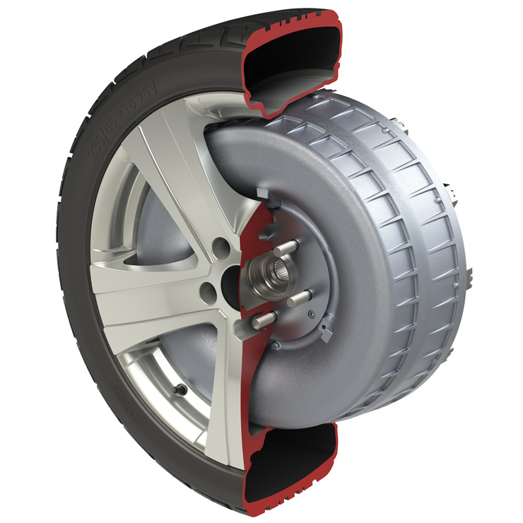
The motor has been designed with the stator attached to the wheel hub and the rotor forming the outer part of the motor. This ‘inside out’ arrangement has a number of mechanical advantages.
First, it has been possible to use the standard vehicle wheel bearing as the motor bearing, thus taking advantage of the excellent reliability of automotive wheel bearings. The bearing stiffness is of critical importance as it affects not only the air gap but also the deformation of the main motor seal between the rotor and the stator.
Second, the rotor components (magnets and so on) require no retention to prevent them becoming detached, as they would in a conventional motor, where they would be placed on the periphery of the rotor. In Protean’s case, the rotor and back-iron form the retention. This has a small benefit in terms of simplification, and helps to reduce the air gap – a key performance parameter.
Fundamental architecture aside, the mechanical design of the motor is conventional. The stator consists of toothed laminations wound with copper wire. The windings are encapsulated, and heat generated in the windings (copper losses), along with a proportion of iron losses, are transferred to the liquid coolant (a 50/50 mix of water and glycol) through the slot liner and iron laminations.
The success of the cooling strategy relies on selecting the optimal materials for the slot liners and the potting compound, both of which must be as thermally conductive as possible while maintaining high dielectric strength. The coolant path is designed to offer cooling to the power electronics too, so there is both a radial and axial aspect to the flow path.
The radial part of the coolant circuit runs between the power electronics and one end of the stator. The axial section of the coolant circuit comprises channels that run lengthwise along the inside diameter of the stator. The effectiveness of the cooling system and the health of the machine are monitored using temperature sensors incorporated into each sub-motor.
The motor is designed for a lifetime of 300,000 km/15 years/8000 hours, and accelerated testing is used to verify that this target is met. It is vital that such durability is engineered into a new product if the end-customers for new vehicles are to be convinced of the benefits.
The overall design is very compact and has some clever packaging, but it is also worth considering what the design omits. With an in-wheel motor acting directly at wheel speed, there are no transmission inefficiencies to factor into energy loss calculations or cooling requirements, and there is of course no transmission to package in the chassis along with the motor.
There are also no CV-jointed driveshafts, which are a further small source of inefficiency. However small the gains made by deleting the CV-jointed shafts, such improvements in fuel economy would be welcomed by producers of IC-engined vehicles, or electric vehicles with chassis-mounted motors, as a significant development. Being able to delete components that produce mechanical losses is important, and it is only with wheel motors that such losses can be eliminated.
Some interesting results were presented to the Cenex-LCV conference in 2017 that showed the improved efficiency of a BMW i3 equipped with Protean in-wheel motors compared to the OE BMW powertrain.
It is not possible to dissect the results to show exactly where the efficiency gains came from, but the average energy consumption over a combined USHwy, USDDS and US06 drive cycle was 3.6% lower with the Protean system. Much of this will have been due to the PD18 being able to dispense with the losses associated with the OE transmission, differential and CV-jointed driveshafts.
The Protean motor, requiring no transmission and having incorporated the power electronics, means it is a simple mechanical installation job to convert an existing IC-engined car to a hybrid or full EV, as there is only the battery and some cooling to package on the chassis.
It is this ease of installation and vehicle integration that has allowed Protean and its installation partners (such as Mahle Powertrain) to produce the wide range of technology demonstrators mentioned earlier.
Brakes
The space inside a conventional wheel on an IC-engined vehicle is fairly uncluttered, and is usually occupied by a brake disc and caliper; in fitting a wheel motor to a vehicle, the major concession that needs to be made is to remove them. It is unrealistic for a motor to provide all of the braking needs for a vehicle without becoming too bulky or requiring some other method of dissipating the electrical energy if the battery is already fully charged.
In making a wheel motor that displaces a conventional brake system, Protean needed to provide a mechanical alternative, which has been achieved in conjunction with well-known brake manufacturer Alcon.
The brake system has an ‘inside out’ design that comprises a brake disc fixed on its periphery to the Protean rotor case. Two calipers per wheel are attached to the back of the stator housing on a bracket. The brakes are hydraulically actuated.
Such brakes have been used previously, notably by Buell on some of its production motorcycles. For Buell this fitted well with its unusual design philosophy, and the load path from disc to tyre is short and very direct, but for Protean this design is simply good sense. It would be much harder to try to replicate the usual set-up for an automotive brake disc, and the result would be heavier as well.
The attachment of the brake disc to the rotor case is via floating bobbins, which again is another feature of motorcycle brakes. In the case of the Protean motor, the use of these bobbins is not to aid race bike design but a sensible solution to keeping heat away from the motor. Tests involving repeated heavy braking during brake durability testing showed that the bobbin system is very efficient at protecting the motor from brake heat.
The choice of two calipers rather than the one found on most production vehicles is also based on sensible engineering choices. The space for the brake disc is radially narrow and, inorder to have sensible pad life, the use of a single caliper would in turn require using long, narrow pads.
Two calipers also make sense from a mechanical loading point of view. Splitting the braking load reduces forces and moments that will affect the air gap between stator and rotor, causing it to change locally during braking.
By halving the braking forces transmitted at any single point of the disc means the stiffness of the rotor casing does not have to be increased to the same extent as for a single-caliper brake system. This system therefore produces a motor of lower overall motor weight and inertia than would be possible in a single-caliper arrangement.
Sealing
Compared to a conventional motor, the in-wheel motor is much more demanding when it comes to sealing. A conventional radial flux motor will not find itself partly submerged when driving, but that can happen to the Protean motor if it meets water that’s appreciably deeper than the depth of the tyre sidewall.
The rotor casing is effectively a dish, and it is at the rim of this dish that a seal is needed to protect the motor’s internals. Protean has developed a seal that is tested in various ways, including spraying it with grit-laden water. A second line of defence after this seal is the potting of the windings and the power electronics, and coating other components.
The seal is rated to IP67 and IP69K ingress protection, which means it can withstand being submerged in water or drenched with high-pressure, hightemperature sprays such as heated pressure washers.
Unsprung weight
The initial (and natural) reaction of many engineers to the idea of a wheel motor is to mention undesirable increases in unsprung weight compared to a conventional car with driveshafts. There is indeed an increase in unsprung weight, but it has been shown by Anderson and Harty (3) that with the usual optimisation and suspension tuning work that would be done during vehicle development, the ride and handling characteristics with significant additions of mass at the wheel differ little from those of a production car.
After much predictive modelling, subjective and objective test work, their conclusion is that the ‘modern development toolbox’ available to vehicle dynamics development engineers is undoubtedly capable of providing good dynamic performance to a vehicle equipped with in-wheel motors. Their work looked at all aspects of vehicle dynamics, and assessed the performance of a standard car versus one with additional mass at each wheel, focusing primarily on roadholding and ride comfort.
The application of normal engineering development processes would overcome any real disadvantage of additional mass at the wheel, and it was noted by Anderson and Harty that there is significant scope for improving vehicle response and dynamics by controlling each wheel motor individually. Examples of how the control of wheel motors can help would be techniques such as torque vectoring and ESP braking, and work has also been done (4) on how inwheel motors such as the PD18 could help with roll stability control and yaw stability control.
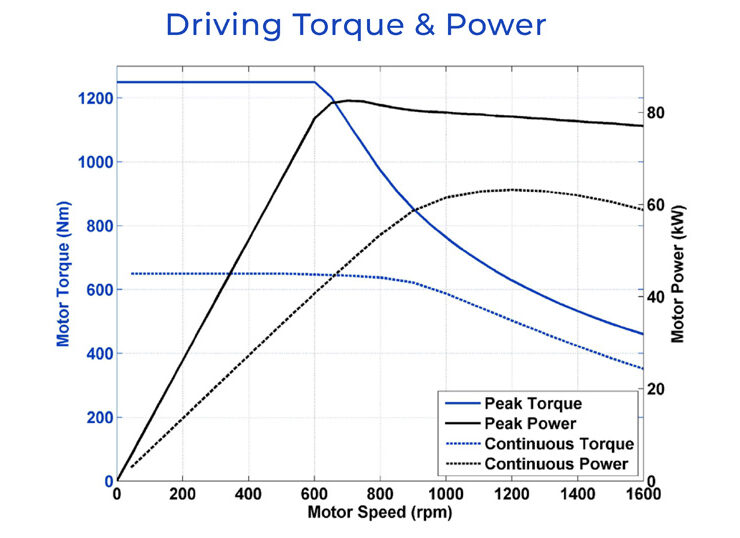
Motor performance
The nominal performance figures for the Protean motor are a peak torque of 1250 Nm per motor. That is close to the maximum torque that could be applied to one tyre in perfectly dry conditions for a typical 2000 kg car without breaking traction, assuming a coefficient of friction of 0.9 between road and tyre.
The continuous torque is 600 Nm, and the peak and continuous power ratings (based on a 400 V DC supply) are 80 kW (107 hp) and 60 kW (80 hp) respectively. The motor, including the power electronics, has a peak efficiency of 93% in both drive and regenerative braking modes.
Summary
Having provided an electric machine that offers very attractive packaging and impressive efficiency (both electrical and mechanically for the overall drivetrain), the Protean wheel motor is at the higher end of the scale of technology readiness level, as evidenced by the wide range of technology demonstrators of various types that have been produced.
Companies with big ambitions such as Local Motors and Fisker, who are looking to produce vehicles for ‘Transport as a Service’, find the packaging advantages of the Protean motors particularly attractive for their planned autonomous vehicles.
The fears about additional unsprung mass have been largely disproved through simulation and real-world testing using simple representative masses. Anyone who in the past would have simply brushed off the suggestion of a wheel motor because of such concerns now have authoritative reports to show that they are certainly not insurmountable.
Anatomy of the Protean Drive PD18
Motor type: radial flux permanent magnet, external rotor
Operating voltage: 200-400 V
Power output: maximum/rated, 80/65 kWTorque output: maximum/rated, 1250/650 NmMotor weight, including power electronics and brake: 36 kgLength: 125 mm
Diameter: 433 mm
Number of phases: three
Number of poles: 32 (four sub-motors, eight poles each)
Casing material: aluminium
Stator material: laminated steel/copper windings
Winding type: distributedCooling: water/glycol
Power electronics: IGBT
The PD18 is a radial flux, brushless, permanent magnet electric machine. Its general form is toroidal, with the permanent magnet rotor forming the outer diameter of the machine and the inner fixed to the suspension upright.
The aluminium die-cast rotor case contains the laminations and permanent magnets. The outer rotor casing also forms the mounting for the brake disc, which is integrated with the motor.
The rotor attaches directly to a conventional wheel hub that contains a conventional automotive wheel bearing. This bearing also acts as the bearing for the rotor. The motor is a conventional three-phase machine, but it is novel in that the stator is effectively wound as four sub-motors, allowing the others to function normally if a ‘quadrant’ develops a fault. Control of these four motor quadrants is via four inverters that are also packaged as an integral part of the stator.
The stator also acts as the reaction structure for the vehicle brakes. The caliper mount for the two diametrically opposed brake calipers, which have been developed specifically for this application by Alcon, is attached to the inboard side of the stator.
The brake calipers are unusual in that they clamp the disc from the inside rather than the outside. Each twin-piston, sliding-type, hydraulically actuated caliper houses two conventional brake pads.
The brake disc is mounted to the rotor with a bobbin system akin to that found on many motorcycles, in order to limit heat transfer from the brakes to the rotor. The load path from the brake to the tyre is via the rotor case.
Some key suppliers
Electronics: AB Micro
Wheel bearings: SKF
Wire: Essex
Winding machine: MarsilliPotting machine: HubersAssembly tooling: ATS
Castings, stampings: undisclosed
Plastics: undisclosed
Protean background
Protean was founded in 2008 and now employs more than 100 people in the US, the UK and China. Its business model is to develop wheel motors to the point where the technology can be licensed to OEM or Tier 1 customers, allowing them to control manufacturing and costs.
The business was born out of a company already well-versed in developing electric machines, which enabled Protean to focus purely on developing the PD18 in-wheel motor, which integrates the motor and the power electronics in a simple and compact package.
Protean has invested well over a million hours in developing its wheel motors (there is a less powerful and smaller PD16 version which is compatible with 16 in wheels), and has covered more than 675,000 km in vehicle trials and testing with the PD18. The motor has been developed in 31 different types of vehicle, which shows the versatility of its design.
In designing and developing the PD18, the company has been awarded more than 130 patents. It had 25 patents before 2015, and by this year a further 75. Over that period, the motor torque from its 18 in designs has risen from less than 800 Nm to 1250 Nm.
References
1. Watts et al,“The Technology and Economics of In-Wheel Motors”, SAE Paper 2010-01-2307, 2010
2. Boughtwood, M.,“Electric Motors”, US 8688346, United States Patent and Trademark Office, April 1, 2014
3. Anderson, M., and Harty, D., “Unsprung Mass with In-Wheel Motors – Myths and Realities,”AVEC 10, the 10th International Symposium on Advanced Vehicle Control, published by Loughborough University, 2010, ISBN 0-9049-4765-3
4. Kawashima, Kiyotaka & Uchida, Toshiyuki & Hori, Yoichi. (0002),“Rolling Stability Control Based on Electronic Stability Program for In-wheel-motor Electric Vehicle”, World Electric Vehicle Journal, vol 3, issue 1, 2009, ISSN 2032-6653
ONLINE PARTNERS


