


")


")


Welding
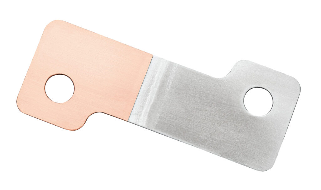
(Courtesy of PST Products)
Nick Flaherty explains the pros and cons of the various welding techniques for connecting cells to form battery packs.
Bonding session
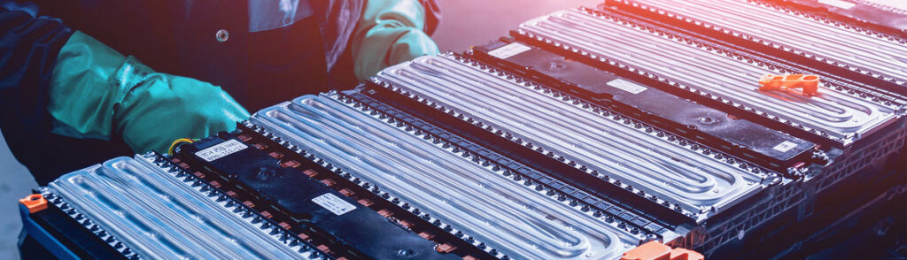
A battery pack in an EV consists of a large number of individual battery cells that are held together mechanically and connected electrically. Making those mechanical and electrical connections poses several challenges, including the joining of multiple thin, highly conductive materials of varying thicknesses and potential damage through thermal or mechanical shock.
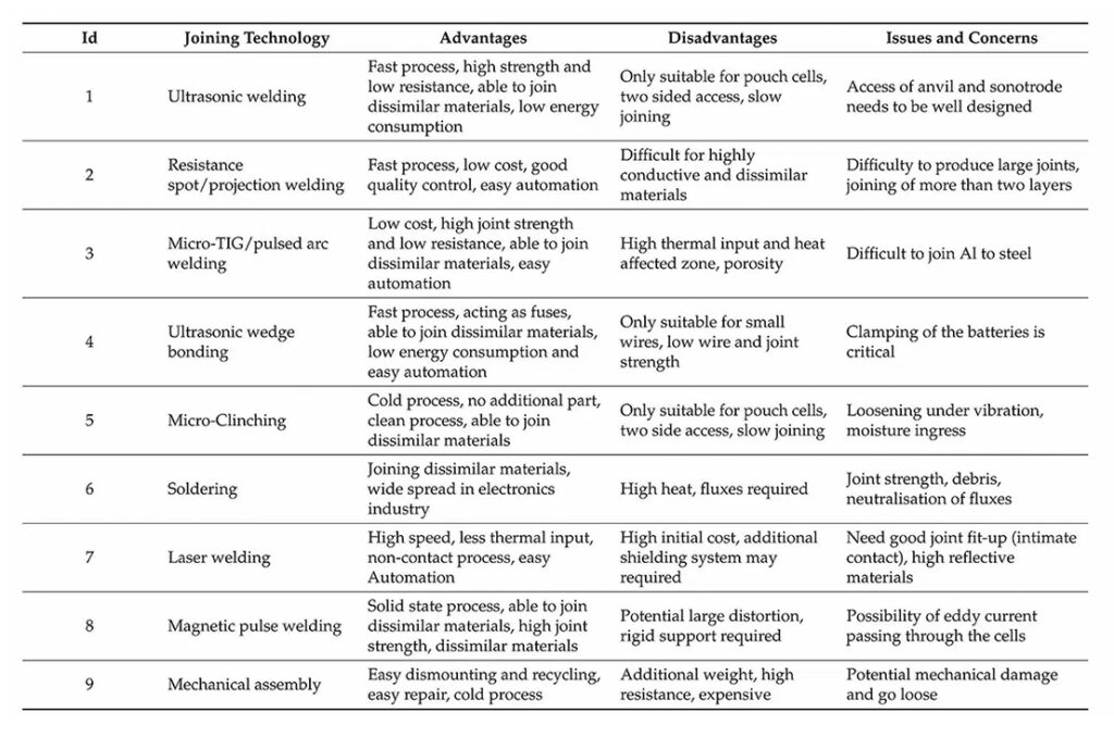
These factors drive the range of techniques for constructing a battery pack, from resistive and ultrasonic welding to micro arc welders, highpower lasers and even high magnetic fields.
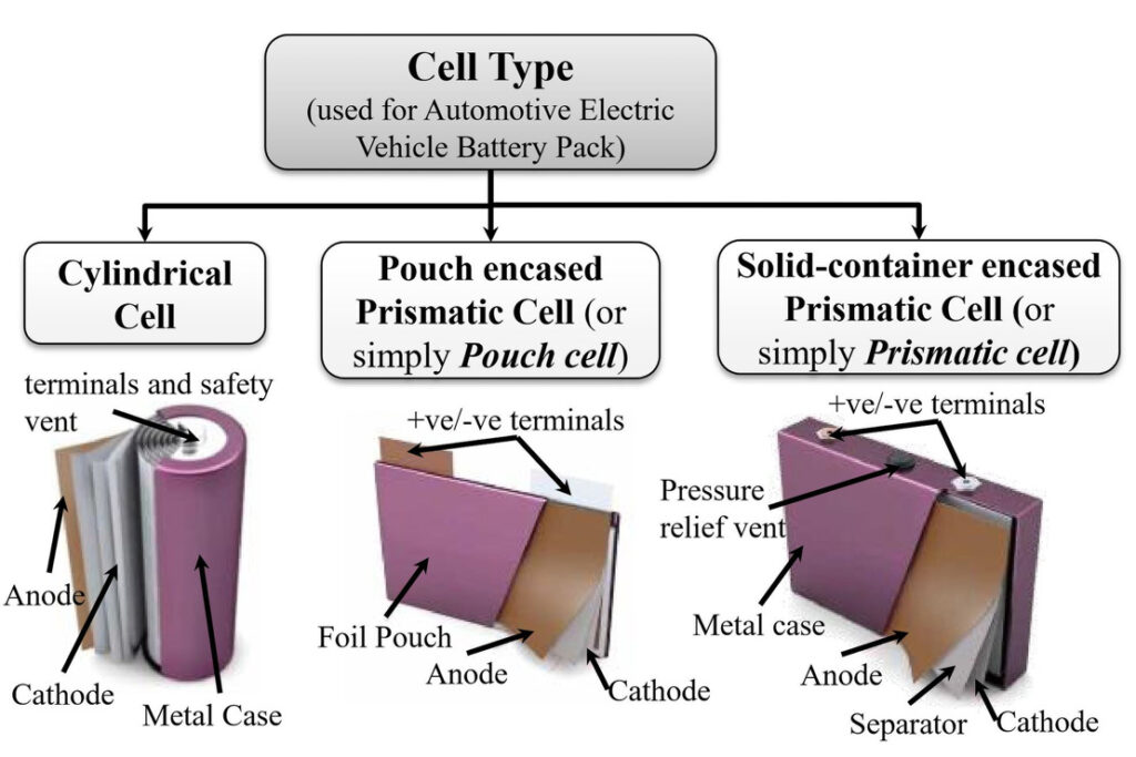
The choice also varies with the type of cell, whether it be cylindrical, pouch or prismatic. The different cell types have different mechanical requirements, but they all need to be protected against high temperatures during the construction process.
Electrical challenges
The key aim for the electrical connections is to produce a joint with a low electrical resistance to reduce the energy loss through resistance and thermal heating, and so maintain the efficiency of the pack. This also helps to keep the temperature of the pack as low as possible during operation.
A high-temperature process such as resistive welding can expose the cell to enough heat to melt or disturb the safety vent, compromise seals or cause internal shorting in the cell. It can also create more fatigue in the cell, compromising the long-term reliability.
Materials challenges
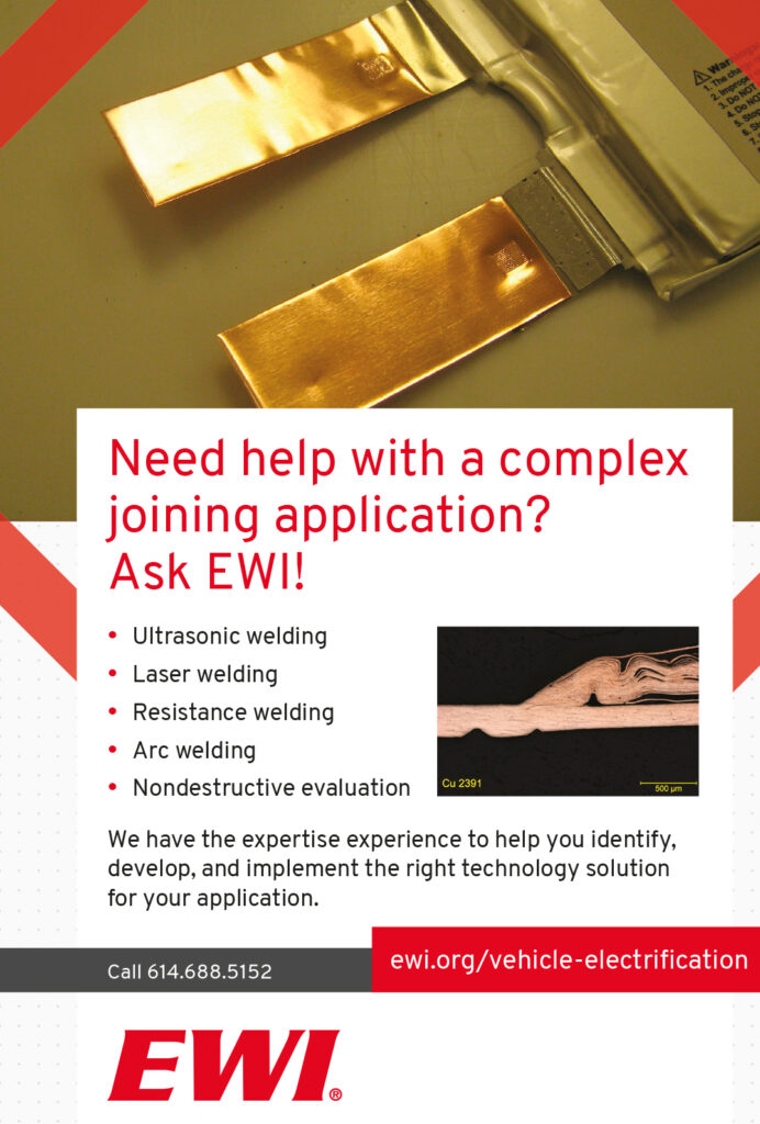
A battery pack has to use different materials, and this creates a challenge for joining dissimilar materials. It can create brittle intermetallic layers with higher electrical resistance and a brittle nature compared with the parent materials. Highly reflective surfaces can be a challenge for processes such as laser welding, while surface coatings or oxide layers can be a challenge for resistive or ultrasonic bonding.
The joint strength is of course vital, and a stronger bond takes longer to create with many techniques. However, the bonding has to be created with minimal vibration that can be transferred into the cells – a key challenge for ultrasonic systems.
Ultrasonic bonding
Nevertheless, ultrasonic metal welding is one of the most commonly used methods. It has been used for various electric cars, including the Nissan Leaf and GM’s Chevrolet-Volt, Spark and Bolt, says Abhishek Das, senior research fellow at the University of Warwick’s Warwick Manufacturing Group (WMG) in the UK.
The method uses high-frequency ultrasonic vibration, typically between 20 and 60 kHz, to join substrate materials by creating solidstate bonds when clamped. The highfrequency vibrations create progressive shearing and plastic deformation between the metal surfaces, producing an atomic bond.
However, the clamping needs access from both sides of the join, with a sonotrode – which creates the ultrasonic vibrations – on one side passing the ultrasonic energy through the join.
Ultrasonic welding can be used for multiple thin foils, dissimilar materials or highly conductive materials such as aluminium or copper, especially for pouch cells. However, it may not be suitable for terminal-to-busbar joints of cylindrical or prismatic cells, as vibration under pressure can cause damage.
Ultrasonic welding is most commonly used for bonding the wires, with bondable surfaces made from electrolytic nickel, aluminium and ENIG or ENEPIG (electroless nickel immersion gold and electroless nickel electroless palladium immersion gold). In the battery pack of a Tesla car, for example, each cell has two wires that act as fuses (one each for the anode and cathode) and are connected using ultrasonic wedge bonding.
For prismatic applications, wire bonding is a common connection method for the voltage sensing signal. This is usually from a busbar onto a PCB. The busbar metallisation is typically 3003-quality aluminium while the PCB is ENIG or ENEPIG.
(Courtesy of the Warwick Manufacturing Group)
The aluminium for collector plates and busbars is usually of 3000-series quality. For cylindrical cells such as 18650 or 21700, the bondable surface is typically electrolytic nickel.
Round wire is commonly used for cylindrical cells, but for prismatic cells ribbon bonding could be more beneficial, says Dirk Siepe, head of process technology at ultrasonic equipment maker Hesse Mechatronics. Aluminium ribbon bonding is a more robust process, not just for current capability but also mechanical stability and thermal conductivity.
The aluminium ribbon would be a much stronger interconnection method when bonding from the prismatic cell onto the busbar. If there is an aluminium tab connection to be made to the busbar, the wire bonder could be used as an ultrasonic interconnection machine, which doesn’t have wire or ribbon beneath the bond tool – it ultrasonically attaches the two metals together.
Once wire bonds are completed, they are subjected to various tests. The most common, the pull test and the bond shear test, are destructive.
For the pull test, a hook is placed mid-span between the two bonds and pulled until the wire breaks. The optimum scenario is that the wire breaks mid-span. The secondbest scenario is the wire breaking at either bond. It is not desirable to have lifting, where the entire bond wire lifts away from the surface.

The main reasons for doing a destructive pull test are to check for adhesion, heel strength, loop height, correct wire diameter and contamination detection. For bond shear testing, this test is for wire diameters larger than 100 microns.
The basic concept is that a shear tool pushes the bond from the side until it removes it from the surface. The force is evaluated, as well as the remnant. A general rule of thumb is that the minimum bond shear force is the tensile strength of the wire and at least 25% remnant, but more than 50% is preferred.
The shear test’s main goal is to measure adhesion of the wire onto the surface. Other items that the bond shear test is useful for is detecting contamination and die cratering.
Hesse has patented a quality monitoring system for ultrasonic wire bonders called Process Integrated Quality Control, says Siepe. This calculates a quality index for each bond based on real-time feedback signals of mechanical oscillation of the bond tool, friction at the bond surface, transducer current, ultrasonic frequency and bond deformation.
If the bond does not meet or exceed the quality threshold, the wire bonder can be set up to do a non-destructive pull test on that particular bond, stop the machine or flag that part for further evaluation.
Resistance spot-welding
Resistance spot-welding (RSW) exploits the electrical resistance at the mating surfaces when high current passes through them to create localised heating and fusion of materials under pressure. This can be used to join different tab materials up to 0.4 mm thick, including steel, nickel, copper and aluminium. Using aluminium and copper together can be difficult, because of their high electric and thermal conductivities and the oxide layer on the surface of aluminium.
A variant called projection welding uses projections on the tabs that act as energy concentrators for the weld and also greatly increase electrode lifetimes, because a flat-end RSW electrode can be used instead of a domed one.
Despite offering easy automation and good quality control though, RSW has challenges arising from the different melting points of the materials and the heat generation, especially with highly conductive materials.
(Courtesy of the Warwick Manufacturing Group)
The assembly process for cylindrical cells requires joining methods at two levels: electrode foil-to-tab joining and terminal welding from the tab to the case.
Alongside ultrasonic techniques, resistance welding is commonly used for both of these, although laser welding is increasingly popular for the foil-to-tab connections. Terminal welding may be less common if the line of sight is obscured owing to the design of the pack.
External current collectors are added to connect cylindrical cells to the pack, and these can reduce the contact area, resulting in more concentrated heat generation and allowing faster welding at a lower current compared to spot-welding.
More stable high-frequency power supplies with more accurate control allows for tungsten inert gas (TIG) welding – otherwise known as microTIG – as another option. The more stable arc from micro-TIG systems allows for finer pulsed arc welding for copper-to-copper joining.
Pouch cells
In pouch cells, the internal electrode stack is contained within a soft plasticaluminium laminate package. Current collectors are welded internally to terminal tabs that protrude through seals to allow external connection. Use of plastic-metal laminates for the cell pouch reduces the amount of packaging but needs a more complex module structure to constrain the cells.
During fabrication of pouch cells, the electrode current collectors are connected to the positive and negative terminal tabs and to the case. The electrode-to-tab welds are conventionally made using ultrasonic technology because of the need to create a joint through a stack of foils, and RSW is not appropriate as RSW electrodes are prone to picking up highly conductive cell terminal/ electrode and tab materials, says Das at the WMG.
However, laser welding technology can be used for pouch cells if the foils are in close contact and a pulsed laser is used to avoid overheating. In the case of pouch cell case sealing, typically a compact heat sealer is used to seal aluminium-polymer laminate films.
At the pack level, module designs typically position positive and negative terminal tabs either at opposite ends or at the same end of the cell according to series or parallel connection requirements. This means the cells are joined either by tab-to-tab or tab-tobusbar connections, which suits ultrasonic welding. Here, RSW projection welding or micro-TIG pulsed arc welding can also be used.
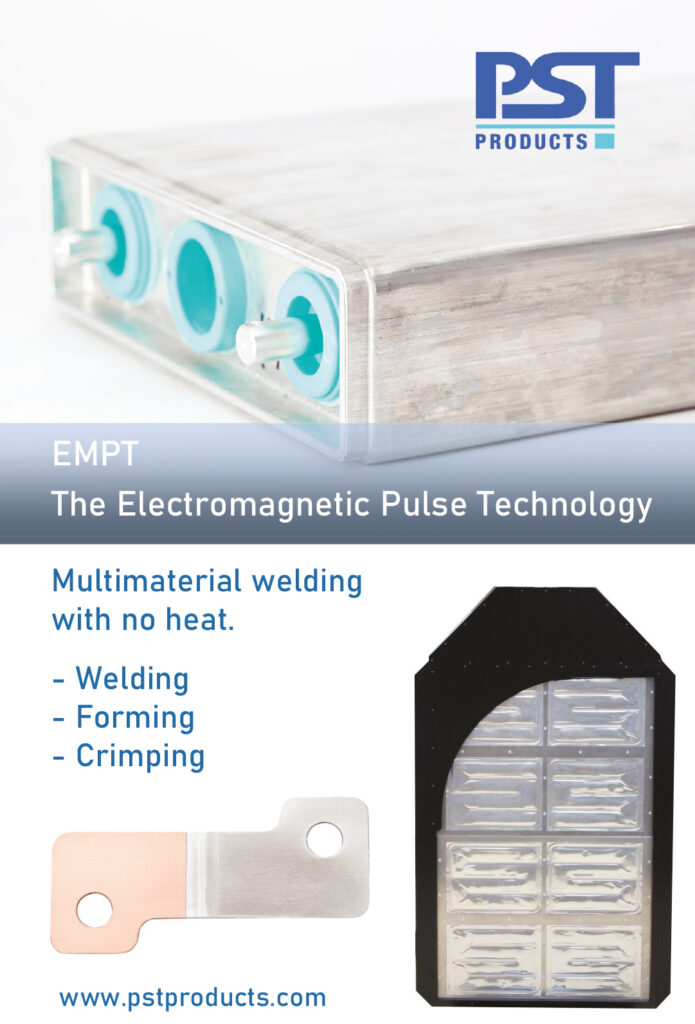
It is in this area that magnetic welding or electromagnetic pulse welding can be used for joining pouch cells tab to tab or tab to busbar without creating heat or vibrations.
Prismatic cells
More battery pack makers are looking to use prismatic cells, which have more of a structure than a pouch cell and are larger than cylindrical cells. The metal container of the cell ensures structural stability, mechanical robustness and humidity protection.
In addition, it allows for the use of safety features such as pressurerelief vents, which are not possible in pouch cells. In some cases, prismatic cells can allow packaging to be more efficient than with cylindrical cells
(Courtesy of PST Products)
The connections for prismatic cells are similar to cylindrical cells – between the current collector tabs and electrode foil using ultrasonic welding, the collector tab and battery terminal using RSW, and the case using RSW or laser welding.
Module and pack-level joining is performed mainly using mechanical nut-and-bolt fasteners or clip fitting. These can be easily disassembled and have a higher joint strength compared with other joining techniques, but there can be issues with high contact resistance and the maximum torque on the nuts and bolts to avoid internal damage.
In some cases, laser welding has also been used for connecting cell terminals to busbars. Ultrasonic wedge bonding and micro-TIG between terminal and busbar may be feasible for prismatic cells.
However, the design of a prismatic pack may have to be changed if ultrasonic bonding is chosen, as the cell terminals are not directly connected with busbars.
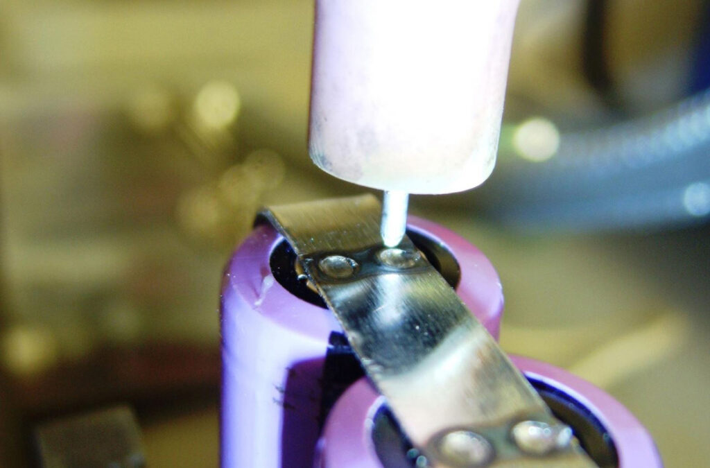
Spot-welding strips and tabs onto batteries in order to make battery interconnections and larger battery pack assemblies is a common production technique. Typically, battery interconnections are made from nickel strips, often designed with splits and projections that are then resistance-welded using parallel gap or step welding methods.
For the best and repeatable results, such methods rely on the quality of the weld heads, electrodes and the power source.
Battery pack manufacturers are looking for methods to attach more conductive interconnects, such as aluminium and copper, while trying to reduce costs by simplifying the interconnect design. Such requirements mean resistance welding can’t be used, as the interconnection is simply too conductive.
TIG
Micro-TIG welding is a highly efficient non-contact method for generating localised heat. Like resistance welding, a controlled and therefore easily monitored current is passed into the elements to be welded.
Unlike resistance welding, the heat generated is due to the resistance of the electric arc and its associated current, and hence is independent of the product’s conductivity and is more localised. This therefore provides a highly controlled method of developing localised welding temperatures that are suitable for joining materials up to 0.5 mm thick onto conductive battery cans.
The TIG battery welding process has been tested and proven with a number of battery pack designs using nickel, aluminium and copper flat. The high degree of control offered by the power source enables the resultant spotwelds to be optimised to size while minimising heat penetration into the battery can.
Precision micro-TIG welding requires a controlled current to be passed into an electric arc. The heating effect is directly proportional to the current and resistance of the arc, which itself depends on the arc gap. With a fixed gap, the arc resistance develops a voltage across it by virtue of the welding current. This can then be used as a process monitoring variable.
MacGregor Welding Systems, for example, provides a range of closed loop controlled current micro-TIG welding units that are suitable for welding conductive material to battery packs.
In combination with custom TIG torches that provide electrical return contacts and arc shielding, these units are readily configured for manual pack assembly or highvolume, multi-spot pack assembly with automatic step-and-repeat torch positioning.
Copper tab battery welding
The 250i2 EV from Sunstone, for example, is a copper tab battery welder with a motorised weld head. This allows for solderless connections where the metals are fused together at the weld spot for a continuous connection and no voltage drops.
During the welding process, surface contaminants are burnt off, allowing for strong, clean welds, and the heat-affected zone is very small and localised to ensure no degradation to the battery.
For nickel tabs, Sunstone‘s CD400DP spot-welder is combined with its WH2125 parallel weld head. The first pulse heats the weld surface to eliminate contaminants and to seat the welding electrode tips. The second pulse then performs a strong spot-weld. This process is designed specifically for battery pack spot-welding.
Spot-welders provide the ability to fine-tune the energy for welding nickel tabs to batteries while also providing enough power to weld thicker terminal tabs. The WH2125 provides fine control of weld pressure from 3 to 15 lb. Each electrode’s pressure setting can be adjusted individually.
Laser welding
Laser processes can be adapted to most of the joining tasks on the cell, module or pack. Laser beam welding is used to join similar or different materials without the need for filler material, for example aluminium to aluminium for sealing prismatic cells or copper to aluminium to connect the tabs of the cells to the pack’s terminal. Additional filler material can be useful when building battery frames.
A significant challenge for lithiumion battery packs in EVs is the complexity of their manufacture. This is not a single battery but an assembly of individual cells that are connected electrically and structurally with a range of different metals. This has an impact on the construction techniques that can be used.
(Courtesy of Sunstone Welders)
High-precision laser processing heads can speed up the cutting welding and brazing process for a range of operations with minimal mechanical or thermal impact on the material or the cells. Battery welding with lasers is much faster than with conventional welding tools such as resistance spot-welding or ultrasonic welding.
The process is contactless and, unlike resistance spot-welding, requires access to only one side of the part, enabling greater flexibility, lower cost and simpler and faster methods of clamping down parts.
A key advantage of laser welding is that the process temperature distribution on the workpiece can be controlled very precisely with laser power and beam intensity profiles, enabling welding of a wide variety of sheet thicknesses and materials, including dissimilar materials.
The laser heads have a range of lasers depending on the application, and the key is in the optics and the control system for the welding head to withstand the heating effect of the high power lasers.
The HIGHmotion 2D remote processing head from II-VI, for example, has a power rating of 6 kW for a continuous wave laser for aluminium-to-aluminium and aluminium-to-copper welds, where the back-reflections that are typical when welding highly reflective materials can be a problem.
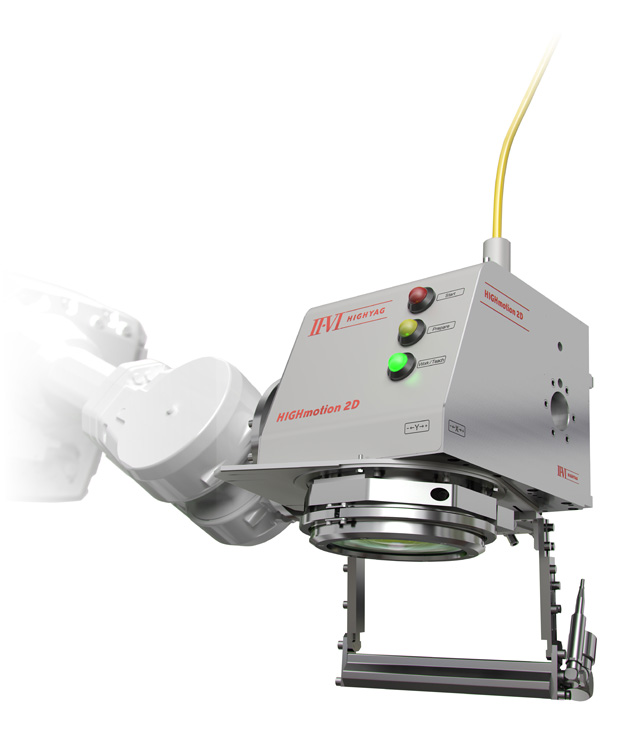
(Courtesy of II-VI)
As a result, the head can be used for cutting anode or cathode foils and sealing the prismatic or cylindrical cell using seam tracking or image recognition. It can also be used to weld tab-to-terminal foils to busbars, busbars to busbars and the lid to a battery.
The system uses reflecting optics based on zinc sulphide and fused silica materials for welding and cutting. Zinc sulphide has a high thermal conductivity to reduce the thermal focus shift, and a relatively high index of refraction that reduces the number of required optics.
Magnetic welding
An emerging approach is magnetic welding. This uses a magnetic force from large electrical coils discharging a very high current in a very short time to produce a magnetic field. The capacitors driving the coils charge up to 16-25 kV and discharge in 25 µs into the welding tools, creating several gigawatts of power to deform and weld metals.
This cold-press welding is different from thermal welding as no heat is induced, although eddy currents can be induced in the battery pack. The weld size is typically 10-20 mm wide with an overlap of 5 mm, but the nature of the welding means the complete weld length has to be designed into the tool as it is applied in the 25 µs magnetic pulse.
For a typical 20 mm weld the tool will be perhaps 300 x 300 mm and 400-500 mm high, as the welding zone is small, says Oliver Marschner, technical sales manager at PST Products. The head is then connected to the pulse generator, which operates at the 16-25 kV.
The technique can also be used to form the metal of the pack in shapes with very clearly defined edges that are not otherwise possible. This can allow the pack to fit more closely into a space in a vehicle, eliminating voids and maximising the number of cells that can be accommodated.
Pack maker BYD, for example, uses the technique for welding busbars, combining aluminium with copper. This avoids creating intermetallic phases with different thermal and electrical conductivities.
The other area where magnetic welding is a benefit is cable crimping, which is also driven by e-mobility. As the diameter of cables gets bigger and bigger, the mechanical forces needed for crimping causes problems for terminals that are usually hexagon-shaped. Using a magnetic field creates a homogeneous round shape with no air gap to crimp the large cable harnesses.
Conclusion
There are many possible techniques available for the construction of a battery pack. Building a pack reliably and efficiently without creating electrical, mechanical or thermal problems in the cells is a major challenge that can be solved in a number of different ways.
The content of the pack – whether cylindrical, pouch or prismatic cells – has a significant impact on the choice of bonding technology, and this in turn has an impact on the design of the pack. Newer techniques such as electromagnetic pulses are increasingly being adopted alongside ultrasonic, resistive and laser bonding where appropriate.
ONLINE PARTNERS


