")


")


Battery Testing
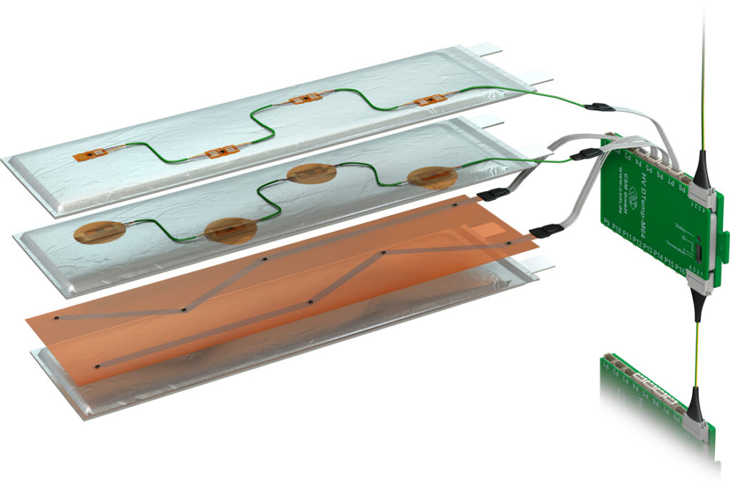
Silicon temperature sensors on a flexible substrate provide digital data for measurements throughout a battery pack
(Courtesy of CSM)
Battery test systems are proving key to speeding up the development times for new batteries, as Nick Flaherty explains…
Time is money
At the heart of testing battery cells, modules and packs are the levels of voltage and current. Temperature and pressure are increasingly important conditions to test at the pack level, while improving the underlying accuracy of the fundamental measurements is naturally a key trend.
Over and above the vital task of improving the accuracy of measurements though is the time factor. Reducing measurement time is increasingly important for tasks ranging from quality control of the materials in cells to new ways of parallel-testing the temperature in modules and packs. It is also about reducing the overall time for soak-testing a wide range of cells and packs.
Many different materials, and combinations of them, are being investigated, and they need to be tested over many thousands of hours. That creates a significant test challenge.
New test techniques, modular test systems and techniques for modelling the battery performance are all helping to reduce the test time of battery packs. This is leading to calls for new standards on how to test effectively and quickly. At the same time, gigabytes of data are generated every day, which needs to be synchronised, analysed and quickly recalled.
Cell and materials
A key driver for the development of a battery cell is to speed up the r&d process and reduce the time taken to develop and characterise the cell.
“If you have an electrode sheet, there’s the cathode material and the dye material on top, and to measure this you measure the interface resistance between the cathode material and the active material,” says Kai‑Scharrmann at Hioki Europe, which supplies test systems to engineers.
“When creating a cell you need the smallest possible internal resistance, and what we can do is help minimise that resistance at an early stage.
“That means you don’t have to finish the cell; you can measure at an early stage and get an indication of the resistance. We take certain measurements of the surface resistance and put them into a 3D mathematical model on a PC.”
The test system uses electric impedance spectroscopy, with the measurement of the current at several frequencies. The key is a probe head that is 1 mm2 with 42 pins and a matrix of voltages and currents that are applied to the material. “There are no limits to the material’s thickness, but you need to know its thickness for the model,” Scharrmann says.
The Hioki system can be used for developing new lithium-ion cells, particularly in Europe but also in Asia where most cells are developed and produced.
The system can also be used for quality control, when buying sheets for manufacturing the cells and for testing the quality of incoming cells. Here the test time is vital.
“When you buy the anode and cathode as sheets with the foil to put together for a cell, you need quality control for cell manufacturers that don’t make the dye themselves,” Scharrmann says.
Other test systems are used in other areas of cell development, such as the combination of the electrodes and the electrolyte.
Here a system called a PAT cell is used for testing. Sebastien Muller at test equipment supplier El Cell says, “We come in at what kind of electrode materials can be used with what combination of electrolyte, so we are a step ahead of the fundamental research but behind the guys that do manufacturing tests.
“The key is that you can look at various materials using the same basic assembly in the lab. You assemble the model battery, put it into the PAT cell and characterise it using our testers,” he says.
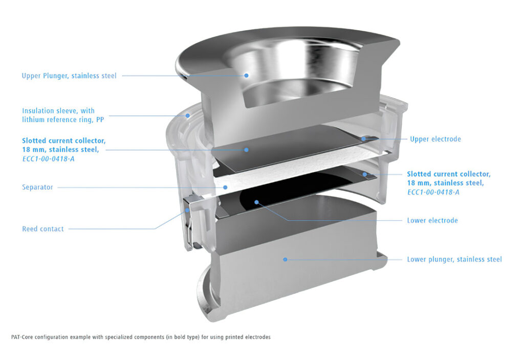
“With layers of electrolyte and anode materials on a carrier foil, you punch electrodes into it and connect to the system,” Muller says. The technique uses impedance spectroscopy to characterise the resistance of the cathode and the anode using a reference electrode.
“Usually the anode is tested against a lithium reference electrode, and the cathode is tested separately against the lithium reference. We do both in one run, with a full cell with the lithium cell alongside – that gives much more information than half-cell measurements.”
Calibration is also a key part of the test process. Many systems have to be sent away for calibration or require a visit from an engineer.
“There is no way to calibrate the absolute potentials; all you can measure is potential difference,” Muller says. “We have an RC network as a test set-up that defines the series and parallel circuits to calculate the response functions of the network behind it. That is used for checking and calibration, and then the testers implement their own calibration procedure so there is no need for site visits.”
Module and pack tests
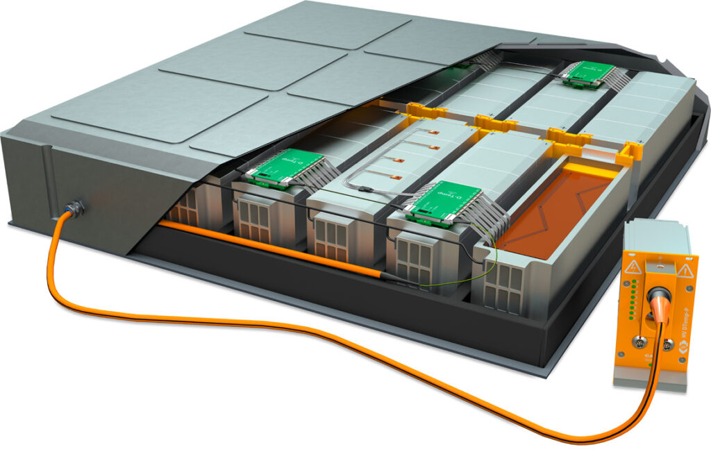
Measuring the temperature of thousands of cells in a battery pack quickly and accurately is a considerable challenge.
“With so many cells, you need hundreds of measurement points in the pack,” says Dr Jurgen Braunstein at test house CSM. “Then you run into space problems, so you need to bring the sensor measurements out, and then you have hundreds of holes in the battery pack, and that’s a mechanical issue.”
“The traditional approach, using a PT100 sensor or thermocouple, runs the cables out of the pack,” he says, “You can combine four or eight signals but that’s still lots of cables to the signal processing outside.
(Courtesy of CSM)
“Instead we replace the analogue sensor with a digital sensor that measures the junction voltage of a semiconductor and so determines the temperature. These are 1 x 1 mm and 0.5 mm thick, with a digital bus such as I2C, so we take these chips and put them on a flexible PCB with a digital controller that converts the data to a bus format such as CAN.
“This allows you to assign names to each channel via the ID of a chip so you know exactly which sensor you are measuring,” says Braunstein. The flexible PCB also matches the geometry of the pouch cells that are stacked in a battery pack, with the sensors in between.
The thin, flexible substrates survive the packaging and cells’ expansion over hundreds of cycles while retaining accurate positioning.
“The challenge of putting all the sensors in the pack requires meticulous placement to 0.1 in, but using the PCB technology allows this and provides galvanic isolation to 1 kV,” he says. “We can have 512 measurements on one cable so there is only one hole in the pack.” These measurements are all brought out to a measurement unit that then connects to the rest of the test system.
While this system is used in r&d, the resulting data is vital for the production line. “We can determine the locations where the production sensor has to be to measure the temperature efficiently, for example to find any hotspots,” Dr Braunstein says.
Test labs
“As a test lab, for us there are challenges and concerns that the battery makers don’t always appreciate,” says Rich Byczek at Intertek. “Personal health and safety for lithium, new designs, higher energy density – often the testing we are doing is to make sure those hazards don’t happen as we push batteries to their operational limits and beyond.
“This requires robust internal health and safety procedures, staff training, the right facilities and an understanding of the limitations of the equipment to handle a battery safely.”
Such test labs provide assurance services, assessing the quality of manufacturing issues for third-party cells, providing failure analysis of cells and helping to do pre-test compliance tests. All of this provides assurance that the battery is as intended, comparing different suppliers against a ‘golden sample’ with known properties or datasheet, either at the paperwork level or going deep into the assembly of the cell.

One issue is obtaining samples as quickly as possible for testing: shipping lithium cells by air is subject to strict rules, as they can catch fire when they short-circuit. “We try to address that by having labs around the world to reduce air shipments, especially of prototype batteries and test samples,” Byczek says.
“Another issue is the architecture of a battery, for example if it’s possible to ship a module rather than a full pack. If we can qualify at the module or cell level then that’s less restrictive and reduces the potential risk in the lab.”
“There are a lot of benefits with a modular design. This is becoming a higher priority challenge in the testing industry – if you cannot break the pack down into building blocks with safety circuits able to operate at a module level then there’s a problem,” he says. “A modular test gives you better granularity of the test data.”
Brand new technologies have to go through a vetting stage, looking at the capacity reduction over time, and lifecycle testing over multiple discharge rates and multiple temperatures, to build a matrix for predicting the battery’s life.
As a vehicle designer adopts new chemistries and cell manufacturing processes it becomes critical to revaluate the ageing factor. That means manufacturers have to go through multiple qualification processes, even with the same cell and pack. However, new chemistries and designs don’t have test data for comparison, so the test lab has to build that quickly.
Lifecycle testing also helps to flush out any manufacturing issues. As long as the lifetime is predictable across a range of cells, consistent ageing across them is expected, so any cells that are out of range are an indication of faults in manufacturing.
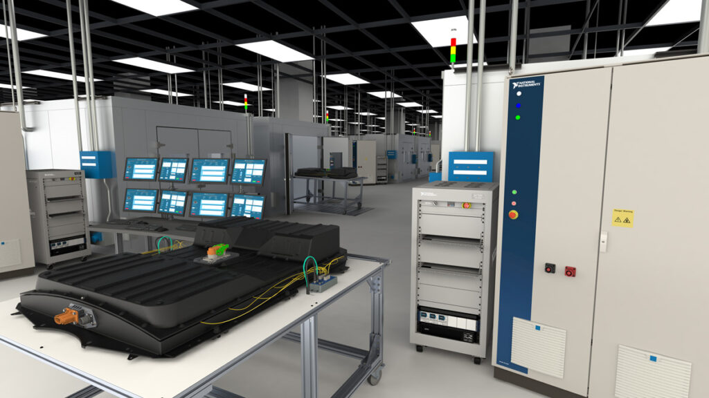
With so many different e-mobility platforms, from e-bikes and off-road vehicles to mainstream cars and electric construction equipment, the battery pack can be subject to different regulations around the world. “There’s a wide variety of vehicles on the market, and therefore a huge range of battery packs that need to be tested,” says Siavash Dezfouli at test lab operator AVL.
“Lithium-ion batteries face specific challenges such as the ability to handle a thermal runaway, so battery testing is essential to ensure safety. AVL has its own simulation software and hardware to verify and validate testing of thermal runaway.”
All this helps determine which tests are required and which design limitations come into play. For example, the test lab has to understand the global market and the differing regulations in Germany, the US, Canada or China. There may be different restrictions on the layout of the battery, plus temperature and environmental concerns.
Global network
With multiple vendors of equipment for a global network of labs, having similar scripting software – the automation portion – is more important than having common hardware platforms. The focus is more on the acquisition and software interfaces.
Lab operators also have to consider serviceability and maintenance, as hardware suppliers may have maintenance personnel in a region; if not, the lab operator may have to look at other suppliers. This is especially relevant for suppliers of large test systems such as vibration systems and temperature cycling equipment, which tend to be local.
The wide variety in vehicle segments in the market creates a huge range of battery packs that need to be tested. Areas such as fire safety and abuse testing are key, and these can be time consuming.
“Most of the focus for testing is on validation and verification, sitting between the design team and production test team, so there are needs for efficiencies on both sides,” says Nate Holmes at test equipment maker NI (formerly National Instruments).
(Courtesy of AVL)
“The validation team have the issue of connecting to the design teams and dealing with fast-changing designs as the technology changes,” he says, “Every time the design changes, the test requirements and the equipment change. The test goals for validation are looking at characterising the battery pack, how long it will last, how it handles extreme conditions, and investigating and exploring the boundaries, whereas in production the question is, ‘Did I make this properly?’”
Those different goals lead to very different test requirements. On the production line for example, the test system has to put full power through the batteries to check there are no bad connections, so there needs to be a multiple test battery cycler for fast testing.
In contrast, validation looks at ageing effects and lifecycle analysis, and tests last from a couple of weeks to a few months to over a year. Because of that, test engineers have to build many duplicate test stations to get the statistical data, which means multiple stations working in concert. Then there is a data management issue – some labs have hundreds of parallel testers all running different versions of the tests.
“Take the case where the design team is testing three variants with three different parameters – that can’t be done serially on a tight schedule,” Holmes says.
“We see one approach to bring everything together in an enterprise level database, where the data can be automatically updated, so technicians don’t have to go to every test cell to take the measurements,” he says.
“It’s also important to make sure the data is searchable so you can run analysis while the tests are still running. You can see the trends in the data and catch any test failures early, so you don’t have something that invalidates the test on day 2 of a 75- day test.”
The central need in such test systems is data aggregation and remote access.
“Depending on the tests, there may be 10-20 Gbytes per day per test cell. How are you saving that – to a raw data file as a bundle of values; is it structured or do you need to do a lot of post-processing? It’s about putting some thought into the data structures.
“You have to have a thermal chamber as well, as the battery’s performance is temperature dependent. You also need a battery cycler, to provide the power levels to and from the pack, and then you need comms to a battery management system [BMS] and to measure the temperature and voltage at the cell, module and pack levels.

“We are seeing the trend to higher voltage levels, from 400 to 800 V or even higher, and the aim is to deliver a higher peak power to service the demands of the vehicle,” Holmes says. “Even if you have an 800 V device the peak power may be much higher, and the test system has to be able to deliver that peak as well as the average power. The test system also needs to be upgraded each time you make that jump.”
For pack and module tests, the key is designing the test station to be as flexible as possible to deliver on the aggressive schedule and still get the required test coverage.
“The actual measurements aren’t that hard,” Holmes says “The difficulty comes in the long test times and getting the confidence of the design and development teams that the system works and that we can change the designs, the bus voltage, and how the BMS works. The test team can adapt to that without extra cost and time.”
Accuracy
Then there is the accuracy of the measurements to consider. To take one practical example, the WT5000 Precision Power Analyser from Yokogawa is being used by Solar Team Twente to maximise the battery life of its solar-powered EV, the RED E. The WT5000 was instrumental in reducing its power consumption.
“We were looking for that extra 1% efficiency to give us an edge over other race cars,” says Rob Krawinkel at Solar Team Twente.
“When you are already at better than 95% efficiency, eliminating any remaining losses is really hard. You have to be able to look at a detailed level at tiny deviations in voltage or current. That means you need a really accurate and sensitive power measurement system.”
(Courtesy of NI)
To validate the accuracy of the battery ‘fuel’ gauge, the car’s onboard sensor measures the battery’s state of charge. The system measures the current flowing into the battery from the solar panels and flowing out to the motor. This provides the residual charge in the battery.
“With the WT5000, we also discovered that the current sensors in the fuel gauge circuit had an offset, which was making the car’s state of- charge measurements inherently inaccurate,” Krawinkel says. “By compensating for the offset, we could confidently provide the driver with a vital extra 1 or 2 km of range from the battery at a given speed.”
The WT5000 has a measurement accuracy of ±0.03%, with a measurement bandwidth of 10 MHz for voltage and 5 MHz for current. The maximum sampling rate of 10 million samples per second exceeds the data refresh rate required to validate the RED E’s fuel gauge system.
Leak testing
Many battery packs require complex cooling systems, and one key area for testing is to ensure they do not leak. They can use air or other gases but require significant control. Again, speed of test on the production line is vital but, unlike traditional engines, every vehicle design can be very different.
“The largest testing requirement for the battery pack is leak testing,” says Gordon Splete at Cincinnati Test. “In packs, modules and cases the subassembly can have coolant, so they all need to be air-leak tested, and as they get larger the leak rates increase. This follows the ideal gas law where thermal change can be an issue.”
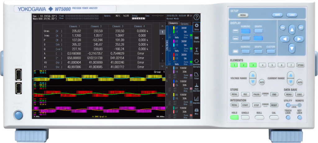
(Courtesy of Yokogawa)
Air-leak testing has to be performed before the functional test (where the battery pack is powered up) as this generates heat. For the ideal gas law the temperature has to remain constant, so if there is a thermal increase it is not repeatable. “For a case-leak test, if there is heat left in the system it’s a really hard test because of the thermal issues,” Splete says.
Another approach is to use pressure decay testing. This uses a differential pressure decay to get a finer resolution on any leaks, so the test can be performed faster. Here the pressure change over time is calibrated to a flow rate.
“We can see pressure changes down to 0.007 Pa,” Splete says. “We use a differential 24-bit transducer analogue to- digital converter to refine the signal, because you can see the difference between a known good part and an accepted part more quickly. That depends on the air volume, so larger parts take longer. For production testing, this can take seconds rather than minutes.
“If you need more throughput, for example with multiple test stations, we will look at other technologies such as trace gas testing. But there are drawbacks with using a trace gas, as well as an associated cost. When you evacuate a part and backfill with helium or a forming gas, and use a tuned leak detector to measure trace gas leaks, it can be a faster test and can reach lower reject rates.”
There are ways to recover and reclaim the gas, but at lower pressures. For example, a powertrain will be tested at 3500 psi while a battery pack will be tested at 1-2 psi.
Mass flow testing is another technique used to test large parts such as battery cases. “When you have a large surface area that can change temperature, you hold the pressure constant and measure the amount of air that goes in to keep it at that pressure,” says Splete.
“There are a lot of tricks to making that work correctly, such as measuring and compensating for atmospheric pressure, but it is all based on the resolution of the flow meter.
Thermal test
For thermal testing of lithium-ion battery packs, researchers at Imperial College London have developed a metric to compare the thermal performance of battery packs.
The technique measures the temperature gradient across the layers in a lithium-ion cell during operation. This allows a comparison of different cooling techniques for the packs in EVs without giving away details of the pack.
Heat-transfer specialists favour the Biot number, which describes a body’s ability to transmit and dissipate heat. Mechanical engineers prefer definitions of thermal conductance and thermal conductivity though, which define the rate of heat transfer that can be achieved through a material for a given temperature gradient.
Neither method can calculate the temperature gradient across a cell when it is in operation, because electrochemical cells generate heat throughout their own volume. However, the cooling coefficient is straightforward to measure in the lab using temperature sensors.
(Courtesy of BMW)
The team investigated the large pouch cells used in the Nissan Leaf, which have a cooling coefficient close to 5 W/K. Small cylindrical cells, such as the ones in the Tesla Model 3, perform less well, with a cooling coefficient of less than 0.5 W/K.
That will help designers evaluate trade-offs between thermal management and energy density, improving the working performance of the whole pack. Computer simulations might be helpful for assessing the potential of cells as well.
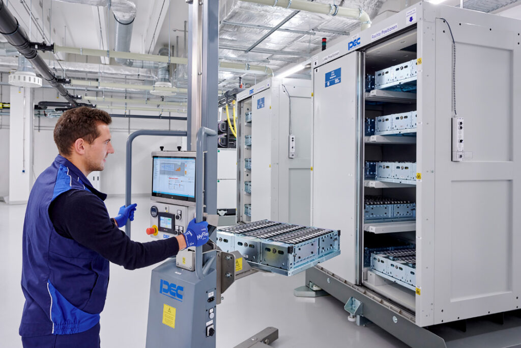
Production tests
For faster production tests, Keysight’s Scienlab equipment is being used for a battery cell production test system at the BMW Group Battery Cell Competence Centre in Munich, Germany.
The system uses the Scienlab battery test equipment to provide precise measurement results, coupled with Keysight’s PathWave Lab Operation software.
This manages the planning and execution of test procedures including schedule definition, management, control and monitoring of the battery test systems and device under test. It also analyses test results as well as the overall efficiency of the lab to identify potential improvements. This helps to minimise the test time.
ONLINE PARTNERS


