


DC-DC converters
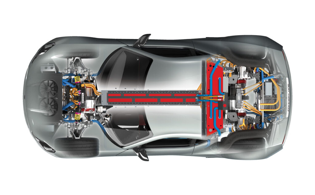
(Courtesy of Rimac)
Peter Donaldson investigates the technology that underpins these essential voltage switching devices.
On the level
In modern pure electric and hybrid vehicles, battery voltages of 300- 400 V is becoming common, 600 V is gaining ground and 800 V systems are starting to emerge, all to help produce more power yet keep current flows and cabling manageable. However, these voltages do not suit all the electrical loads aboard the vehicle, so a means of converting them to lower or sometimes higher levels efficiently is essential. That is the role of the DC-DC converter.
Also known as auxiliary power modules (APMs), they can be found in every EV or hybrid with a high voltage battery. Fundamentally, this is because direct electronic conversion between voltages is much simpler and more efficient than the indirect alternative of taking a feed from the high-voltage inverter to power a motor and belt drive for a low-voltage alternator. In functional terms there are basically two kinds of DC-DC converter – one to bring high voltages down, the other to convert between different voltages at the low end.
A vehicle’s main DC-DC converter typically takes a battery’s voltage down to 12 V for common car loads such as headlights, window motors, pumps and so on. It also has to be adjustable, as some loads may need outputs in the 12.5 to 15.5 V range, while 42 V might be needed by power steering systems, for example. Power outputs range from 250 W to 3.5 kW, although some onboard chargers (OBCs) handle more than 6 kW; about 7.4 kW is regarded as the practical limit.
Critical loads on the low-voltage side, such as steering, are driving an increase in functional safety requirements for converters, while reliability demands are also growing because vehicle OEMs want to reduce the size of the low voltage battery.
In some applications, APMs also convert a voltage upwards to help start a hybrid vehicle or provide back-up power, which requires a bidirectional capability. This type of arrangement is typically found in mild hybrids, converting between 14 and 48 V.
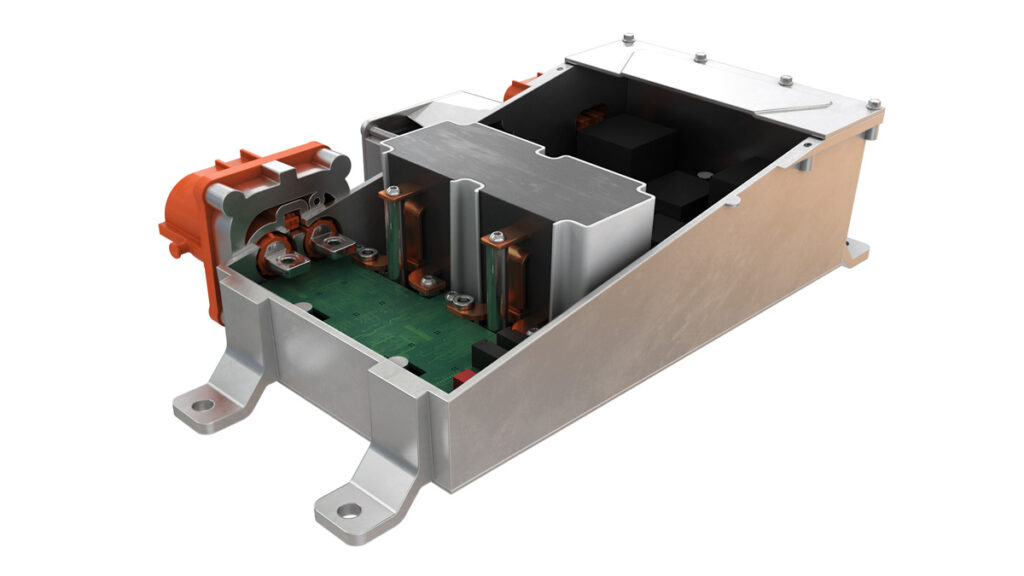
What’s in the box?
Inside the enclosure of a modern step-down DC-DC converter is a set of components including electromagnetic devices such as transformers that reduce the voltage at the input, capacitors that store energy, semiconductor switches that regulate the output and capacitors that filter it. Digital control logic implemented in devices such as FPGAs is also included, because a lot of computation is required to take full advantage of the increased switching frequencies enabled by new semiconductor technologies.
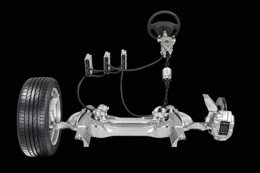
(Courtesy of Infiniti)
These all have to be integrated and packaged in a compact manner while still managing thermal losses to keep temperatures down. The smaller the converter the more concentrated the heat loads become and the greater the challenge involved in extracting that heat efficiently.
Development challenges are the familiar interrelated ones of size, weight, efficiency, reliability, electromagnetic compatibility, high voltage isolation for safety, and robustness against the often harsh operating environments to which vehicles are subjected.
One specialist consulted in connection with this article stresses that customers are pushing for greater power densities in particular, which means a move to much higher switching frequencies. With higher switching frequencies come shorter switching cycles, which means that other converter components, such as the magnetics in the transformer for example, do not have to hold power for so long and can therefore be made smaller.
DC-DC converters are evolving to provide other functions such as pre-charging, which involves using the low-voltage supply and boosting it to begin powering up high-voltage loads. Another is active discharging, in which circuits in the converter are used to bleed down high voltages in other components as the vehicle powers down. All of these require reliable protection and communication with the vehicle’s primary ECU.
Voltage versatility
Vehicle OEMs are also asking for greater freedom to adapt to manufacturers’ different electrical system configurations. There is a growing demand as well for multiple output voltages on the low-voltage side, all controlled by intelligent software and with facilities for data recording.
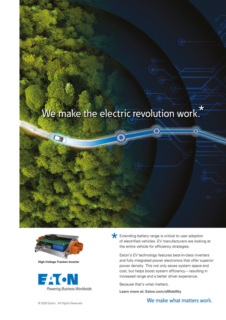
(Courtesy of Eaton)
DC-DC converters are essentially devices that perform auxiliary functions in an EV, so engineering efforts are directed towards making them as small and efficient as possible to minimise their impact on the overall architecture. However, they must still be able to service the growing number and variety of electrical subsystems as electric actuators continue to displace hydraulic and pneumatic systems.
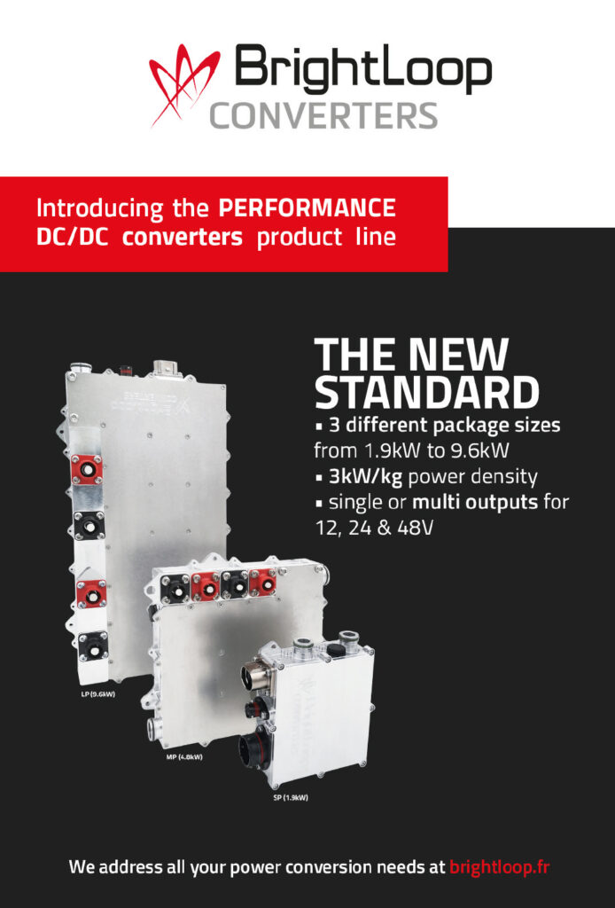
One specialist supplier we consulted has a product line ranging from a 1.9 kW converter for use in small vehicles such as single-seat race cars and motorcycles to a 10 kW unit aimed at large SUVs and electric hypercars. The smaller device weighs just 600 g, says the company.
SiC, transit to wide bandgaps
Technological progress in recent years has come from two main areas – advanced topologies and advanced semiconductor materials.
While there are many topologies in use, they fall into the two broad classes of fixed-frequency pulse width modulation (PWM) and variable frequency quasi-resonant zero-current switching (ZCS). PWM is generally simpler but sacrifices switching efficiency as switching frequency increases, which is a disadvantage when the EV industry is pushing for higher frequencies in pursuit of power density.
ZCS converters eliminate switching losses by ensuring that there’s no current flowing when the switches operate, which is achieved by setting up resonances with capacitors. Because of this ‘soft’ switching, ZCS converters are much quieter electromagnetically and acoustically than PWM devices.
The materials are the wide-bandgap semiconductors silicon carbide (SiC) and gallium nitride (GaN), out of which the solid-state switches are made, either in the form of IGBTs or MOSFETs.
Bands in solid-state physics are energy levels that electrons can occupy. Electrons in the valence band govern how atoms form bonds with others, while those in the higher energy conduction band are free to move in electric currents.
Solid-state electronic devices exploit the fact that in semiconductors electrons can be made to jump between the valence and conduction bands, switching currents on and off. A bandgap is an energy range that, under the laws of quantum physics, no electrons can occupy.
While semiconductors such as silicon have bandgaps in the 1-1.5 eV range, the values for wide-bandgap materials are in the 2-4 eV range. That means it takes more energy to make electrons jump from the valence to the conduction band, in turn allowing devices made from these materials to operate at much higher voltages, frequencies and temperatures than those using conventional materials.
(Courtesy of BrightLoop)
While more expensive than silicon, SiC is cost-effective because it enables higher efficiency, smaller size and higher switching frequencies than silicon, which in turn permits the magnetic components in the converter to be made smaller. GaN is expected to enable further performance improvements.
One expert calls the emergence of these new materials game-changing, because they allow one of the most important components in any DC-DC converter – the heavy and bulky transformer – to be made smaller and lighter, while reducing losses.
However, increasing the switching frequency means everything else about the converter design has to be reconsidered, including the magnetics, integration and digital control. The result, he says, is a dramatic fall in the volume of the converter compared with the best available a decade ago.
The direct effect of increasing the switching frequency, he explains, is the amount of reactive energy in the inductors, capacitors and transformer components. Impedance increases with frequency, he adds, so doubling the switching frequency allows the size of the capacitors, inductors and transformers to be halved.
He cautions, however, that the increase in frequency also brings parasitic side effects, which affect magnetic components in particular and make the copper conductors less efficient. In PWM converters it makes switching events sharper and noisier, increasing the risk of electromagnetic interference.
Anatomy of a charger
At this point it is worth looking at the design of an advanced DC-DC converter – a 6.6 kW SiC OBC that runs at a switching frequency of 500 kHz, built by one of the companies we consulted – and comparing key elements of it with more conventional practice.
To give it its full description, it is a capacitor-inductor-inductor-inductor capacitor (CLLLC) series resonant dual active bridge (DAB) converter. The converter’s winding structure, core arrangement of the series inductor and transformer, and the shape of the heat sink, have all been designed to minimise core volume, transformer intra-winding capacitance and eddy current losses caused by flux fringing – the tendency of a magnetic flux flowing through a core to spread out into the surrounding medium near an air gap.
In a conventional LLC transformer, the frequency would be around 100 kHz and the inductance around 100 μH, and noise increases with frequency. With the CLLLC design, however, the primary inductance can be reduced even as frequency rises. Lowering the inductance also allows the converter’s components to be made smaller.
Higher frequencies can also cause losses associated with the ‘skin effect’, in which the current flow is concentrated near the surface of the wire with very little through the core. That reduces the wire’s effective cross-section and thereby increases its resistance because of eddy currents generated by the changing magnetic field.
A further problem is parasitic capacitance, which is the unwanted storage of electric charge in components that are close enough to affect each other with their magnetic fields. It reduces voltage conversion efficiency as well as causing EMI issues.
Core losses can also increase at higher switching frequencies, as a magnetic core is subject to alternating magnetisation that causes eddy currents and hysteresis – where the magnetisation lags behind the field producing it – resulting in unwanted heat building up and lower efficiency. At high frequencies, these core losses tend to exceed those in the windings.
Core design concepts
The new OBC’s DAB topology exhibits symmetry between its primary and secondary sections to enable higher switching frequencies. Also, it uses several other pieces of detail design that depart from the conventional to minimise the losses and make the charger as compact as possible.
The first of these differences is in the core design. Whereas a traditional converter would have a ferrite core shaped like an open-sided cube with a central pillar around which the wire coils are wound (an ER/PQ core), the DAB OBC has a low-profile UU-type core (two U-shaped cores facing each other) with two separate coils wound onto the converter’s main PCB to create the transformer.
Drawbacks of the traditional core design include poor use of space for the winding and poor heat dissipation for both the winding and the central pillar. The advantages of the UU core configuration meanwhile include a larger surface area for faster and more uniform heat dissipation, and direct winding onto the PCB that allows the use of very thin copper to reduce AC losses. The simple symmetrical shape of the UU core also helps with heat distribution, as the uniform magnetic flux eliminates hotspots.
The next step involves integrating the two resonating primary and secondary inductors, reducing size by sharing a magnetic path and using a winding structure designed so that magnetic fluxes cancel one another out to reduce core losses. These are arranged on an E-shaped core mounted above the transformer. This enables the resonating inductors and the transformer to be closer together without causing mutual interference.
The UU core configuration that separates the windings into two parts also reduces the intra-winding capacitance. It does so by arranging the winding structure to keep opposing current flows as far apart as possible to minimise the voltage difference between the winding layers.
Selection of the core material also plays an important role. DMR50 was chosen because it exhibits the lowest losses within the design frequency and magnetic flux ranges, with further loss reduction achievable if its temperature is kept at around 80 C.
Cutting losses at the fringe
Overall, keeping losses down involves minimising air gaps to reduce flux fringing, keeping the windings away from gaps to avoid the fringing that remains, keeping flux density low to limit core losses, and reducing the region subject to high losses by enlarging the thickness at the top of the inductor ‘E’ core.
Further design measures include removing specific areas of the (aluminium) heat sink that would be affected by the remaining flux fringing to avoid additional AC losses, and extending the heat sink to improve heat dissipation from the inner cores.
The above description applies to the OBC’s power transformer and integrated inductor, the planar form of which reduces the height of the device, although the cylindrical capacitors that share the PCB and flank the transformer and inductor are relatively tall.
The role of those capacitors is to work with the inductors to set up resonance as current flows back and forth between them. The resonance is coordinated with the MOSFET switches to store energy to enable the zero-current switching that minimises both switching losses and noise.
This OBC is a bidirectional converter that can also send power from the vehicle to the grid if necessary. In general, bidirectional converters are more complex than unidirectional ones, as the latter can be based on an analogue regulation loop, while the former have to be digital because they need additional control features to send the current in both directions. This is more demanding in terms of design, control logic and safety architecture, one expert points out.
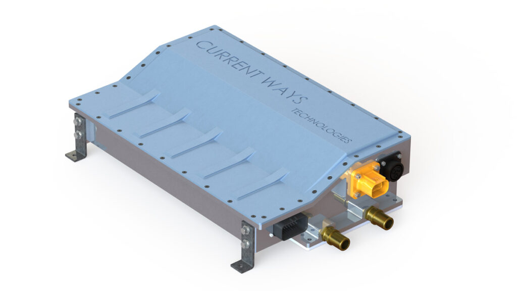
(Courtesy of Current Ways)
Another expert notes that bidirectional converters need both hardware that can drive the current in each direction and software suitable for controlling the current flow. He adds that, in the past, low-cost converters were based on diodes that handled the rectification. Since diodes allow current to flow in only one direction and are also quite lossy, they have largely been replaced by FETs in these applications.
FETs can be driven to act as assisted rectifiers and also as transistors to control the power flow. Most converters therefore have the switching hardware they need to be bidirectional, but they then need effective software to control them, which can be challenging to write.
Another hardware feature required for bidirectionality is symmetry in the electromagnetic components, such as the relative numbers of turns in the input and output windings of the transformer. Where a unidirectional step-down transformer would have fewer turns on the output side than the input, with a step-up transformer a bidirectional converter has an equal number of turns in its input and output windings, and therefore relies on the switches – specifically their switching frequency and period – to change the voltage and power output.
Another important parameter in DC-DC converters is the voltage range over which they operate efficiently. This is defined by the magnetics, particularly their turn ratio, and both the switches and capacitors must also be sized accordingly, one expert says.
Another says the input and output ranges are always translated into a duty cycle or a switching frequency variation, in order to adapt the impedance to different voltages, cautioning that with power electronics you can do anything but nothing comes for free. It is a question of managing trade-offs, as the wider the voltage range over which a converter is designed to work, the less efficient it will be at any given voltage.
Pursuing power density
Power density – kW per unit volume and/or mass – is also a key attribute for power electronic devices including converters, and this is largely determined by efficiency. By definition, high efficiency reduces losses, which emerge as heat and which directly affect how small the package can be made. The topology and cooling method used also play their parts. The magnetics are the most important drivers of size, however, as they require the most space.
While increasing the switching frequency drives up power density, to a point, in converters that use PWM schemes in particular there are trade-offs to be made against efficiency, because switching losses increase with frequency. With wide bandgap semiconductors, one supplier explains, components of any given size and current rating can use lower switching frequencies, so converters can be made smaller without losing efficiency.
He adds that it takes a great deal of know-how and expertise to take full advantage of high switching frequencies. Another benefit of doing so though is that in increasing the switching frequency through the control frequency it is possible to reduce the capacitance so much that chemical capacitors are no longer needed; they can be replaced with ceramic capacitors, bringing significant advantages in terms of weight, volume and reliability.
This supplier claims to have achieved a power density of more than 3 kW/kg in its converters, while incorporating liquid cooling into its latest design.
Closed-loop control
Closed-loop control is a must for modern DC-DC converters. In principle it is straightforward: the standard control logic architecture is used to set up a command, sense the system’s output and then adjust the command to achieve the output target. The key, one of our experts says, is to be able to run this control loop fast enough to control switching frequencies of several hundred kHz (or more) safely and efficiently.
The control software tends to be run on FPGAs or microcontrollers. In either case, they have to sample the voltage in the converter in real time and compute the duty cycle for the next switching operation to close the loop, repeating the process for every switching cycle.
Two things are critical for closed loop control – execution time and deterministic computing. Switching at such high frequencies provides very little time in which to complete complex calculations, so a deep level of coding optimisation is essential to perform the calculations as quickly as possible.
As this is real-time computing, controlling several hundred thousand switching operations every second, even if they are correct 99.9999% of the time the converter will not live for more than a couple of seconds. The calculations therefore have to be 100% perfect and always completed within the allotted time. That can be very difficult if the architecture is not properly designed.
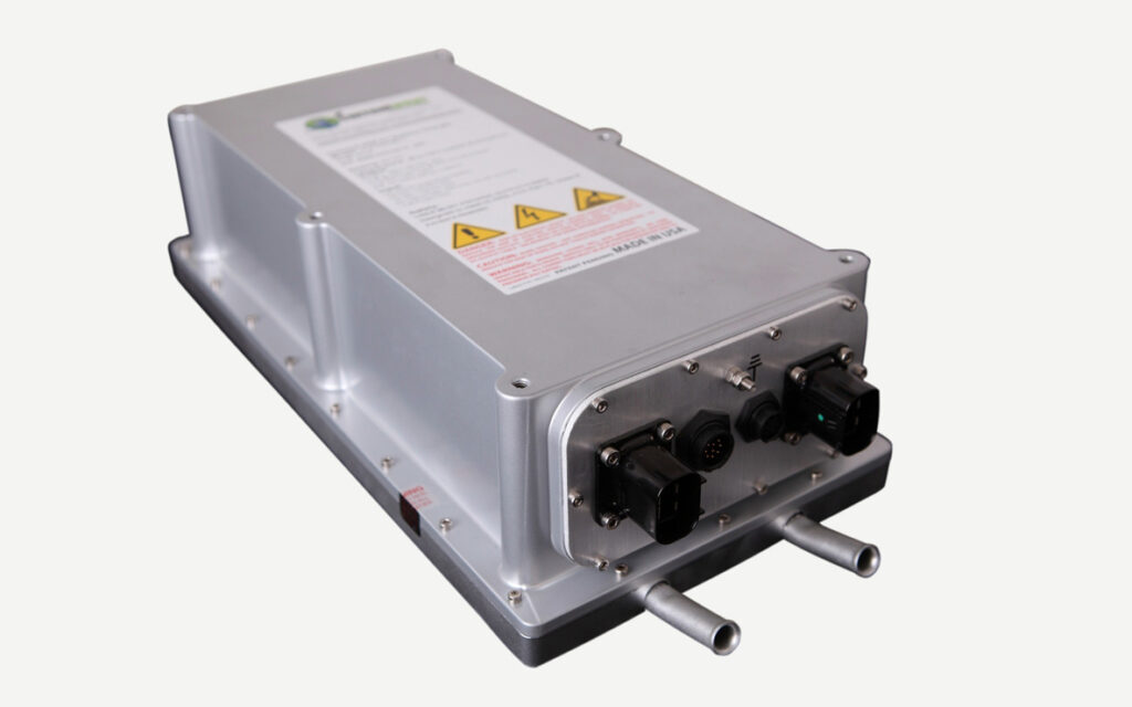
(Courtesy of Current Ways)
Our expert cautions that closed loop control may look simple but it is not, and the know-how required to make it work reliably and efficiently is at the heart of converter developers’ intellectual property. He adds that his company has demonstrated a current loop frequency of more than 2 MHz, meaning one cycle every 0.5 μs.
Also, there is a great deal of scope for optimising the digital control algorithms, which are becoming increasingly sophisticated in the effort to gain power density. Our expert emphasises that because these algorithms are implemented in software, there are performance gains to be had at no additional cost in hardware, creating opportunities to boost the price-to-performance ratio and make products more competitive.
Isolation issues
As DC-DC converters convert electrical power between high and low voltages, whether in one direction or two, they are the points at which the high-voltage and low-voltage circuits come into closest proximity. For obvious safety reasons, principally to avoid the dangers of electric shock, fire and smoke, the converters must maintain reliable separation between voltages.
This is known as galvanic isolation, and is one of the core functions of the converter’s transformer section, as it couples the high- and low-voltage sides via magnetic flux without allowing current to flow between them. Other components can be used in galvanic isolation schemes, however, including capacitors, relays, magneto-couplers, Hall effect sensors and opto-isolators. These last two enable signals to cross voltage isolation barriers.
Safety standards mandate that users must be protected in case of any single failure of isolation inside the converter, a specialist notes. This translates into the need for reinforced isolation, he adds, and is achieved with the above isolator components that send signals across the barriers and in power conversion components such as the transformer.
Safety isolation is another area in which there is scope for innovation to keep overall dimensions down while adding extra creepage distance between the high- and low-voltage sides, he says. Creepage distance is the shortest path between two conductive parts, and designers seek to make it as large as possible to minimise the risk of, for example, a loose piece of solder shorting out a pin carrying high voltage to low-voltage point in the circuit, or moisture or dust bridging the gap.
In a transformer, for example, that gap might be the distance between the primary and secondary windings. In addition to maximising that distance, a physical barrier can be placed between them.
Such a barrier might be formed from a piece of structural plastic that serves as an electrical insulator while allowing magnetic flux to pass through, another specialist explains. This kind of barrier will also provide protection against physical shock that might otherwise force the two sides into contact in an accident.
In most EV applications these days, DC-DC converters are liquid-cooled because that gives good thermal performance and useful reductions in size. However, air-cooling is simpler and remains an option. In low-power applications with efficient converters it can even operate without a fan, simplifying the integration task, although higher power applications generally require forced air-cooling with a fan.
Most of the time though, the converter is sited close to equipment that needs liquid cooling, such as the high-voltage battery and the inverter, and can therefore be plumbed into the same cooling loop fairly easily.
What could possibly go wrong?
While modern DC-DC converters have proved to be very reliable, failures can occur, and if the failure is in the isolation it can put people in danger. Also, the converter is critical to the operation of an EV, otherwise there is only the small capacity low-voltage battery to operate all the equipment that does not run from the main battery via the inverter. So it is worth looking at some of the things that can go wrong.
Overheating can lead to the most serious problems, which is why so much attention is paid to cooling. As well as obvious failures such as insulation and even windings melting and causing major electrical shorts, more subtle things happen as components get too hot, such as core losses increasing.
That not only reduces efficiency, it will also push temperatures up further still and can lead to thermal runaway. That in turn causes inductors to crack and the inductance to fall suddenly, perhaps from 20 to 5 or 6 μH, one expert explains, with control of the voltage and current being lost and damaging other components such as the switches.
When integrating a converter into a vehicle’s electrical system, load sequencing issues can arise when various components that put loads on the circuit come from different manufacturers. There is always work to be done by the systems integrator to ensure everything is properly coordinated.
(Courtesy of Infineon)
With SiC transistors, the instantaneous rate of change of voltage over time, known as dV/dt, is much higher than in converters using switches based on IGBT technology, and this can be a significant source of noise in the car, an expert notes.
He adds that, so far, there is no unified standard for optimising dV/ dt on the high-voltage bus. Until such a standard is established, it is up to the vehicle integrator to work out how much EMI filtering is needed, and it is quite common to encounter EMI when multiple components are installed in the relatively small volumes available.
While heat kills power electronics, the use of design simulation tools, automated assembly processes and components that allow for operation at higher temperatures have all contributed to better reliability. Beyond that, it is important to match the load factors of all the components to ensure that none of them are overloaded, and to avoid any component types with limited service lives, such as chemical capacitors.
Observing these precautions means that service lives of more than 10 years can conservatively be expected.
Future efficiency
Although more is always better where efficiency is concerned, modern DC-DC converters typically manage 94-95%, and chasing the remainder becomes prohibitively expensive as far as automotive customers are concerned. However, the implementation of GaN transistors is likely to change that.
Acknowledgements
The author would like to thank Matt Nolan, Laurent Collin and Bruno Reynard at Eaton, Chris Hsiao and Patrick Ku at Delta Electronics Cyntec, and Florent Liran at BrightLoop Converters for their help with researching this article.
References
Yu, S.Y., Texas Instruments, and Hsiao, C., and Weng, J., Cyntec, “A High Frequency CLLLC Bi-directional Series Resonant Converter DAB Using an Integrated PCB Winding Transformer”, Texas Instruments, Cyntec, 2020 Nardone, K., Curatolo, T., “DC‑DC Converter Technologies for Electric/Hybrid Electric Vehicles”, Vicor Corporation, 2011
ONLINE PARTNERS

