


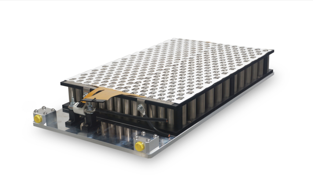
Busbars and interconnects
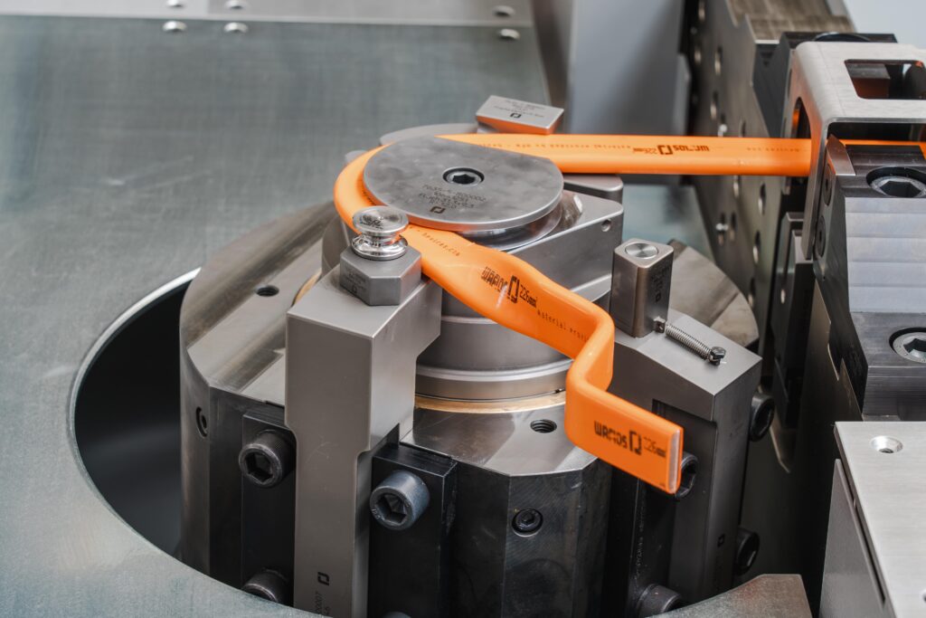
(Courtesy of Wafios)
Joined-up thinking
Peter Donaldson explains the factors at play in designing and producing busbar and interconnect systems
Large EV battery packs can contain thousands of cells that have to be connected to form modules and packs, then connected via busbars to other driveline components such as inverters and DC-DC converters to make robust and reliable connections quickly and efficiently in confined spaces while keeping costs down.
That has made the design and construction of busbars and interconnect systems an important subject of r&d as voltages get higher and the thermal conductivity of their components becomes increasingly important to cooling. Engineers therefore face a set of challenges in designing and manufacturing these systems, particularly in mass-production environments.
General application areas such as automotive, aerospace and marine present similar demands on busbars and interconnects in terms of performance, reliability and safety, but with different emphases. A leading power transfer, management and materials developer highlights the priority given to vibration resistance in automotive applications, weight reduction and space saving in aerospace, and resistance to corrosion in marine environments – although all are important to some degree in all applications.
In terms of regulation, aerospace applications face the most demanding requirements, but they also benefit from the redundancies those regulations mandate, according to a major electrical, industrial and power management company. Performance and reliability are also critical in the automotive sector, as customers increasingly expect zero defects, and being stranded owing to battery issues is unacceptable.
Further, making safe parts efficiently for millions of passenger vehicles at a competitive price is in its own way just as challenging, says a major chemistry and specialty materials provider. Taken together, the charge and discharge cycling requirements, the shock and vibration stresses and the cost targets associated with automotive applications represent a unique set of demands that have to be met with inventive approaches and high efficiency, both in performance and manufacturing, notes a precision metal stamping and ultrasonic welding specialist.
Materials challenges
With a wide diversity of battery technologies and architectures, engineers are expected to provide a large and versatile range of solutions with no compromise on safety, an expert from the power transfer company says.
Conductor material selection is a fundamental task, in which weight, cost and conductance are key factors to be balanced, according to the electrical, industrial and power management provider. Busbar packaging is another hurdle, as space is limited in battery disconnect units and batteries because of creep and clearance requirements. It is also important to offset the applied stress at the electrical interfaces owing to the different rates of thermal expansion and contraction of modules, and to ensure that batteries can be serviced and repaired.
“Huge cost savings can be realised if individual cells can be swapped rather than having to replace an entire cell array,” the company’s expert says.
With busbars, one of the most important considerations is electrical insulation, which is critical to the integrity of the whole electrical system, both in normal operations and in mitigating the effects of thermal runaway, for example, according to an engineer from a major chemicals company. There are many different approaches on the market, the most prominent being extrusion coating with alternatives, including direct overmoulding and the securing of busbars to housings using insulated clips.
There are also many classes of insulating material, with the choice between them being affected by different battery concepts and busbar geometries. Further, the busbars and their insulation need to be designed to handle high currents and voltages, and to dissipate heat efficiently, especially during fast charging.
“A deep understanding of the application and its requirements, and knowledge of advanced materials are needed,” the company’s expert says. “This is the only way to make the right materials decision and is also relevant in terms of scalability and costs – factors that are important for mass production.”
Most current collectors are aluminium, with interconnects being nickel or aluminium alloy. Busbar materials will vary, depending on application, between copper and aluminium. While copper is still ‘king’, one expert reports that interest in aluminium and copper-clad aluminium is starting to grow, while tin, silver and nickel are all common plating materials.
As application requirements become more challenging, and production volumes needed to meet market demand grow, manufacturing techniques are moving towards greater automation and higher levels of control. That means managing process variability and reproducibility are essential.
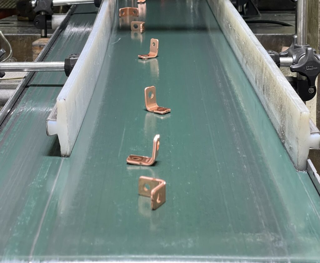
(Courtesy of Wiegel)
Manufacturing evolution
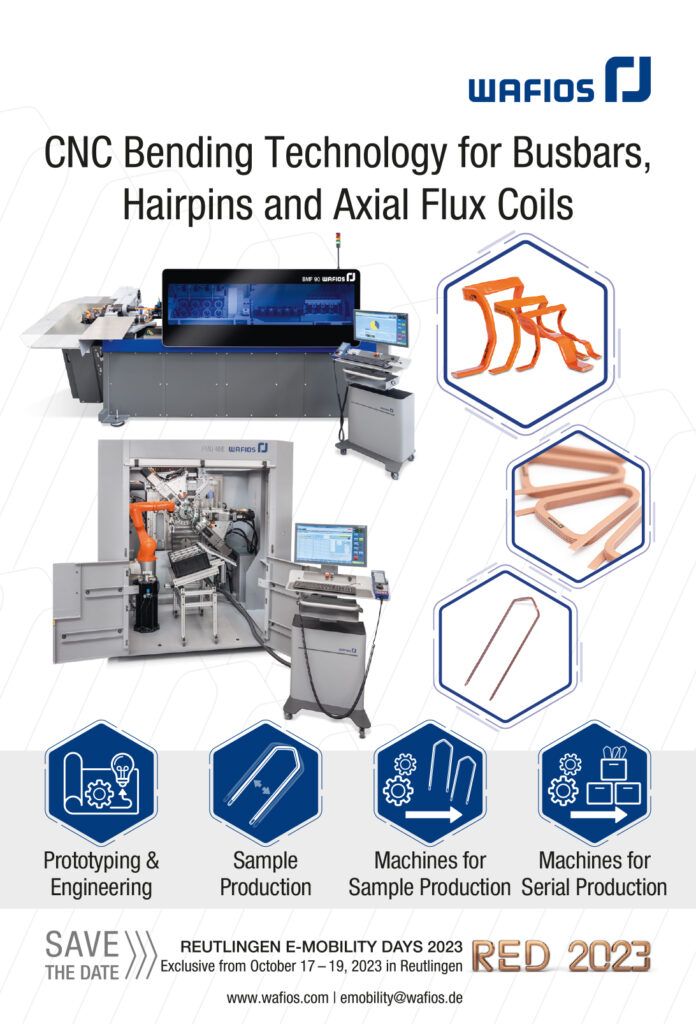
The experts we consulted note that while the techniques for manufacturing busbars have not changed much over the years, the equipment used has evolved significantly. For example, servo-driven stamping presses and CNC bending equipment have increased accuracy and efficiency. On the other hand, no single manufacturing technology has won out, and battery systems rely on numerous technologies within the pack.
In addition to stamping and bending, these can include forming techniques such as photochemical machining or etching, plus the creation of flexible busbars built up from thin layers of coated copper formed in a stack and covered with an insulating coating. Where possible, however, CNC-bent busbars are progressively replacing stamped ones, which reduces waste and capital expenditure.
With the feasibility of mass production being particularly critical in automotive applications, this trend towards CNC bending is becoming significant. CNC bending works with aluminium as well as copper conductors, in both bare metal and plated forms. The technology is flexible, economical in terms of materials and relatively easy to automate, according to a company specialising in the technology.
Busbars are often made from thick wire that is both rigid and flat, the latter meaning it is wider than it is thick, and it routinely has to be bent across its width as well as through its thickness, or even twisted. CNC bending can handle copper and aluminium conductor material that already has its insulating coating in place, making automation easier.
The process is flexible, because the angles and directions through which the wire is bent or twisted, and the length of material that passes through the tool before the bend is made, are controlled by software, says the CNC bending company’s expert.
That means multiple parts with different lengths and configurations of bends and twists can be produced on the same tooling, so long as the dimensions of the stock are within the range it can accommodate, and changes to the design can be implemented as quickly as they can be put into the software. In contrast, with most common alternatives of stamping, the sizes and shapes of the parts are dictated by the tools installed in the stamping machines, and any changes to the busbar design require expensive new tooling.
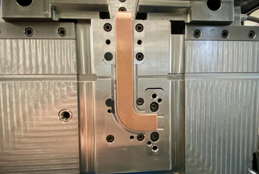
The stamping process starts with a flat sheet from which the tool cuts thin strips; the rest of the sheet, about 50%, is waste. While waste copper and aluminium are routinely recycled, the process requires energy. With CNC bending there is almost no waste, the expert adds, although some of the insulation on the ends of the busbar has to be removed by mechanical or laser stripping to leave clean metal for electrical connections.
Insulation choices
The choice of insulating coatings is wider, with options including the polyamides PA6, PA66 and PA12, polyether ether ketone, polybutylene terephthalate, polyphthalamide (PPA) and polyphenylene sulphide (PPS), all of which are thermoplastics.
For applying electrical insulation, there are several widely used techniques on the market including direct overmoulding, extrusion coatings and clipped housings, in which insulated mounting clips provide a stand-off distance between busbar and housing. So far, there is no clear trend towards one particular technology, according to the expert from the chemicals company.
“If anything, the extrusion coating is slightly preferred for longer connections, which will probably disappear due to battery architecture optimisation,” he says.
“We see manufacturers choosing between extrusion and injection moulding, but many are not choosing just one process because they see the need for expertise in different manufacturing processes. Companies need to master multiple processes to handle diverse customer requirements. It comes back to being flexible enough to make safe, high-performance parts for different types of battery architecture.”

He adds that the challenge with such insulating coatings is that metals and thermoplastics do not naturally adhere to each other, so considerable expertise is required to ensure the bonds between them will survive thermal shock testing.
“We have our own moulding technology and equipment for thermal shock testing, and for thermal runaway equivalent testing,” the expert says. “Sometimes we show parts at trade shows or in meetings where the parts failed thermal shock testing.
“Why show a part that failed? Well, we have plenty of samples of perfect parts, but we also want people to recognise that we have ‘walked the walk’ in doing the tests and going through trial and error and trial again, so that they don’t have to.” That also involves partnering with manufacturers and collaboration in design, he adds.
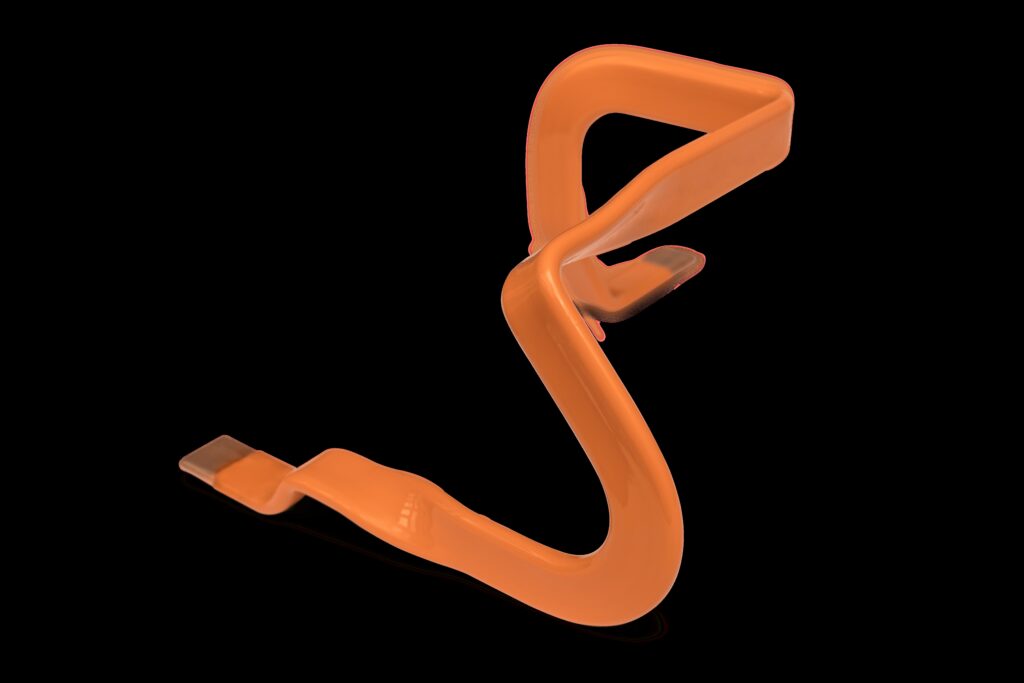
(Courtesy of Wafios)
Reliable connections
Making connections within and between interconnects, current collectors and busbars can be seen as a straightforward process, both in routing the conductors and ensuring reliable electrical contact. However, as battery and powertrain technology develops and increasing energy and power levels require higher standards of reliability and safety, the connection technology has to meet them.
At the same time, battery and powertrain integrators are also looking to reduce costs and cycle times. Such connections are typically made using techniques such as bolting and welding, and there is now also the choice of new types of mechanical connectors that support automated assembly, says the expert from the electrical, industrial and power management company.
With rapid market access a priority, cell interconnection technologies have been kept relatively simple with the use of plastic overmoulded solutions and wire harness. With more recent demands for performance, integration, weight and optimisation, however, laminated busbars have been gaining in popularity, according to the power transfer, management and materials specialist. These are engineered components consisting of layers of fabricated copper separated by thin dielectric materials and laminated into a unified structure.
In battery interconnects, wire bonding and ribbon bonding appear to be the most common means of making permanent electrical contact, but the expert from the precision metal stamping and welding specialist is trying to change that with a patented ultrasonic welding process he describes as an improvement on the status quo.
(Courtesy of Celanese)
Sensing issues
Modern BMSs monitor multiple parameters at the cell, module and pack level, and the need for sensors and associated wiring inevitably has an impact on the main conductors. With busbars for example, voltage sensing leads are now needed to ensure battery management strategies can be realised. While these changes add cost, they help OEMs improve system performance, the electrical, industrial and power management expert notes.
In bent metal busbars, the main requirement to support such measurement systems is to ensure that the areas from which insulation material has been stripped are as clean as possible to ensure there is an absolute minimum of resistance between the busbar and anything connected to it.
In the latest battery platforms, safety requirements and lifetime management require more and more accurate monitoring of both temperature and voltage, along with other methods of detecting early-stage failure modes.
“Those sensors need to be placed as close as possible to battery cells, directly integrated within a laminated busbar, for example,” says the power transfer, management and materials expert. “Also, space constraints in battery modules have required designers to investigate better integration methods, such as moving from wire harnesses to flexible printed circuit board assemblies.”
Architectural impacts
Busbars and interconnects will also be affected by architectural developments such as the adoption of cell-to-pack (CTP) and cell-to-chassis (CTC) battery configurations. CTP and CTC batteries are often structural, and tend to require much larger current collectors, but the basic architecture is generally the same regardless of size.
They can, however, simplify the design of a battery and reduce the number of components required. Eliminating modules will naturally remove the need for module-to-module connections and therefore reduce the number of busbars. Eliminating these interconnections will also reduce the number of heat sources and improve heat dissipation.

“Due to their very specific integration methods, with limited capability to change defective parts or modules, CTC or CTP solutions will increase expectations related to lifetime optimisation and monitoring,” argues the power transfer, management and materials specialist.
Some of the busbars will have to be physically flexible, the expert from the electrical, industrial and power management company notes, and as competing technologies go through the process of maturing, numerous manufacturing technologies will continue to be needed.
The CNC wire bending specialist notes that busbar manufacturers often operate in a “build-to-print” manner, meaning they don’t always know what the final application will be. They receive orders to make parts that can be of any size and shape, and so long as they can be made from the wire stock and the designs conform to guidelines that govern factors such as the relationship between material thickness and bend radii, they will make them.
Regardless of the battery type, routing of the busbars is always the last step in the design, one of the company’s experts notes. “You have your cell configuration and now it is up to the designer to collect plus to minus,” he says.
Sometimes, shapes that cannot be made in a single CNC bending process can be accommodated with one or more additional steps on different machines, but occasionally, he says, they are asked to bend a bar through a radius that is just too small. For example, making a 2 mm radius bend over the “high” edge of a 20 mm wide bar would not be possible with CNC technology.
“There is physically no chance of making such a sharp bend over the high edge, so we normally recommend that the bending radius standard is one times the dimension, so it would be 20 mm with the radius at 20 mm. If a customer wants such a sharp radius, we can use a combination of methods.”
He adds that one emerging trend is for long busbars known as backbones made from wire measuring 40 mm x 6 mm thick or 45 mm x 4 or 5 mm and up to 2 m long. A set might include five to 10 of these mounted close to each other.
At the same time, the new architectures create a demand for the design of flexible busbars and co-extruded long busbars that meet the needs of CTP and CTC designs. This will mean that suppliers will need to work with customers to explore material solutions or new busbar designs.
“Suppliers will have to be extremely flexible, even when they want to optimise manufacturing efficiency by making millions of just one type of part,” the chemistry and specialty materials company’s expert says.
Materials suppliers will perhaps have to be, if anything, even more flexible, as well as being very familiar with the advantages and challenges of the different types of architectures. “We need to speak the technical language of our customers, and understand what they want to achieve, so that their projects can continue to be rapidly developed,” he says. “So the need for expertise across multiple EV battery architectures is a challenge throughout the supply chain, at every level.”
(Courtesy of Mersen)
Moving heat
Electrical conductors in batteries and around the powertrain are of growing importance to thermal management, thanks to their ability to conduct heat as well as electric current. That is leading, for example, to busbars that are larger than they would be if their current capacity were the single factor that went into their sizing. Increasing the cross-section is also a simple way of reducing resistance and therefore heat generation in a busbar, further aiding thermal management.
The CNC bending specialist started with round wire, but has since developed multiple dedicated machines to handle rectangular material. “We see a trend to bigger cross-sections, and greater height-to-width ratio, so we have just developed a bigger bending machine,” one of the company’s experts says.
“Our first machine was able to bend wire of up to 150 mm² in cross-section, but the new one can handle 300 mm² material.” The external dimensions of this larger wire are 51 mm x 5 mm, requiring large machines to bend them rapidly and accurately into shape.
The downside of larger conductors, argues the expert from our chemicals company, is additional cost, weight and bulk that might be undesirable in many designs. “Those are good reasons to find other means of heat dissipation,” the company’s expert says. “This problem could even get worse if the material chosen for busbars is aluminium instead of copper, because aluminium has a lower electrical conductivity than copper, so the heat generation would be higher.”
Ideas about how to overcome this problem include the use of thermally conductive adhesives to dissipate excess heat onto a metal housing, for example.
Incorporating conductors into thermal management strategies brings opportunities to capitalise on new battery pack materials such as advanced thermoplastics. In designs where the metallic conductor can be cooled by a fluid, or indirectly cooled through a thermally conductive thermoplastic, there are multiple avenues to improve designs for thermal management, notes the chemistry and specialty materials company’s expert.

“Thermally conductive thermoplastics help provide electrical insulation and thermal conductivity to conductors and the surrounding components,” he says. “We have also developed the means to test and analyse thermal maps of different conductors in the lab, where we can help manufacturers accelerate understanding of different configurations for the thermal management of such conductors.”
Dimensional stability is critical to ensuring that systems perform as designed, our electrical, industrial and power management company’s expert says, citing the use of graphene in busbars to enhance such stability. This variant of carbon made up of single layers of carbon atoms joined in a network of hexagons can be processed into busbars of extreme flatness, which helps transfer heat out of the system via passive cooling mechanisms, he explains.
Many new applications need high currents because of demanding e-mobility drive profiles and fast charging requirements. Reducing ohmic losses and managing their heat dissipation effect in confined areas are becoming increasingly important aspects of many designs.
“Thermal simulation tools are increasingly used in the very early stages of a thermal management project to take into consideration the whole system architecture and optimise heat dissipation and conductor designs,” the power transfer, management and materials expert notes.
While the cell form factor used in a battery does not affect busbar and interconnect designs in any fundamental way, battery architectures and cell connection systems have had to adapt to cylindrical, prismatic and pouch cells, and the placement of terminals is important, he points out. “Positive and negative terminals are usually at opposite ends of a cylindrical cell, but newer configurations that put both polarities on the same end are gaining popularity in in the market,” he says.
Each form factor has a particular connection solution that the industry has more or less converged on, the precision metal stamping and ultrasonic welding provider’s expert notes, although packs based on cylindrical cells still exhibit significant variation in current collector geometries and design.
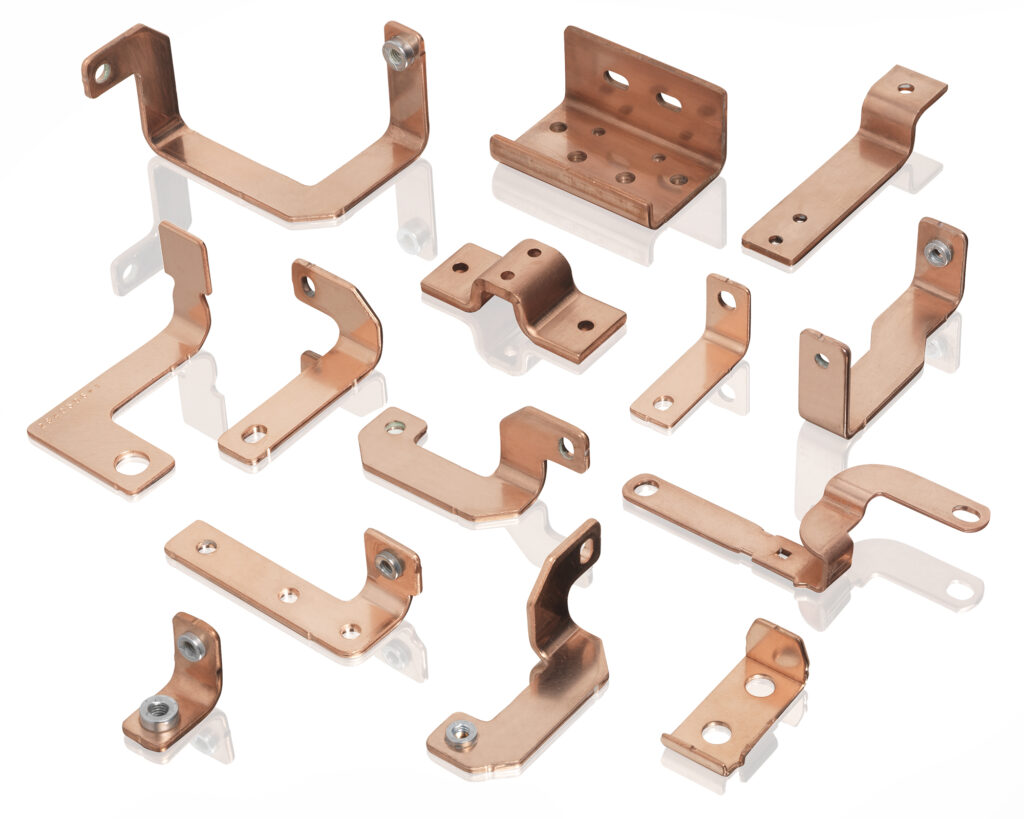
(Courtesy of Wiegel)
Design tools
Design tools such as FEA, mould flow analysis, CAD, CAE and computer aide optimisation (CAO) are as important in the area of conductor design as in any other aspect of engineering an EV powertrain.
A design will usually start with CAO completed with several simulation tools to adapt and optimise the component at the system level, the power transfer, management and materials expert points out. Supporting this will be the interpretation of results from thermal and vibration simulations, which helps to accelerate design cycles.
The CNC bending specialist says its customers can design their busbars in any CAD program they like, so long as they use the design guidelines the company provides to ensure the bars can be successfully bent into the required shape. When the CAD file comes from the customer, it is imported into and analysed by the company’s in-house programming system that checks for feasibility, looking at minimum lengths and bend radii, for example, as part of a full CAD/CAM integration.
“We have an integrated simulation tool, so we can run a simulation of the part to check for collisions [with other areas of the part or the tooling] and run rates,” one of the company’s experts says. Knowing the run rates is important for calculating manufacturing times. “This is available on the bending machine itself as well as in an office setting, so that the customer’s engineers can check parts and run simulations,” he adds.
“This all happens before bending. Then, after the first busbar is bent, it goes into a measuring cell that checks it in three dimensions so that inspection software can compare the results from the 3D measurement cell with the original 3D model that was fed into the machine.
“The software then generates correction data for the second production run, so within two or three cycles you get a part that matches your 3D master. Then, data from whatever you have done on the bending machine and then measured can be exported and fed back into the customer’s CAD system.”
Another of the company’s experts emphasises the importance of getting from the first CAD file to a ready-to-use bus bar very quickly, so the company developed its software to support that goal. “In the recent past, 10 or 15 years ago, the operator had to program the geometry manually, but now it is almost completely automated,” he says. “You just push a few buttons and the system checks, simulates and finally produces a part that is very quickly corrected.”
The chemicals company provides customers with close support with what its expert describes as a very accurate simulation of the thermal stresses between busbars and plastic insulation during temperature cycles. The stresses lead to cracks during thermal shock testing. “With our simulation model we are able to predict the location of cracks and can propose countermeasures for customer-specific geometries,” he says.
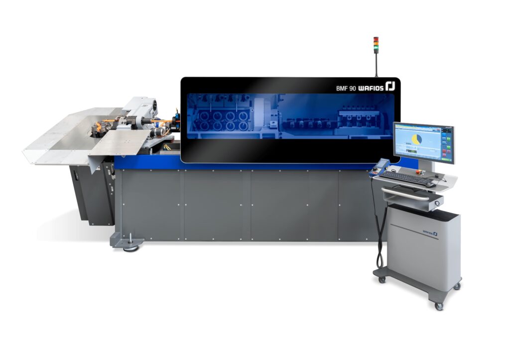
(Courtesy of Wafios)
Improvements and future directions
The technology in and around busbars, interconnects and other major conductors is still evolving, with numerous improvements to products and processes emerging.
For example, busbar insulation inside the battery pack has to be coloured a specific orange for safety reasons. However, when subjected to heat ageing, some material classes turn dark brownish, the expert adds, so the company has introduced new materials designed to ensure that the high-voltage conductors retain their colour throughout the product’s life cycle.
Meanwhile, a range of improved crack-resistant materials for overmoulded busbars – especially for those in e-motors and power electronics – has been introduced by the chemistry and specialty materials supplier. They are based on toughened polyphenylene sulphide, and exhibit “superb” high temperature dielectric properties and perform far better than reference grades in thermal shock testing. Other solutions based on different grades of PPS are in development, as are solutions based on high-temperature nylon PPA.
The company has also developed tools for its own use to validate material performance, one of which is a scouting tool to help find candidate materials and the other a representative busbar for thermal shock testing. The best candidate materials have proven to be free of cracks even after more than 1500 cycles from -40 to +150 ºC, its expert says.
“However, prediction is as important as scouting and testing, since the better you can simulate and predict outcomes, the more time you can save,” he says. “With that in mind, our colleagues have developed new methodologies for predicting busbar failure, and to evaluate how the processing, design and materials all work together.”
The electrical, industrial and power management expert sees value in multiple busbar manufacturing processes, and continues to develop and refine its ability to extrude insulation onto flexible busbars, which are quick to develop, eliminate engineered waste and easy to customise.
The power transfer, management and materials supplier recently launched a new design of laminated busbar with integrated monitoring that is designed to ease assembly and improve battery module safety, along with one using insulation that resists high temperatures for new applications.
The precision metal stamping and ultrasonic welding specialist has patented a new means of producing busbars of variable and compound thickness that enables cell-to-busbar connections to be produced quickly and at low cost. The company’s expert emphasises that providing a current collector complete with cell connection tabs enables customers to eliminate a step at the pack assembly stage.
In future, thermal management will remain a critical issue, stresses the chemicals provider, and busbars might come to active cooling technologies such as liquid cooling, advanced thermally conductive materials or other new concepts. As voltages get higher, aluminium could come to replace copper, according to the chemistry and specialty materials expert, as the self-heating effect will not be as significant as it is at lower voltages, although higher voltages bring their own challenges.
“Perhaps aluminium will harden over the many temperatures cycles, but if heat can be extracted efficiently from them through heat sinks and thermally conductive insulators, they might become a relevant conductor and alternative to copper in the coming years,” he says. “If that’s the case, we’ll be ready.”
Acknowledgements
The author would like to thank Jasmina Simon at BASF; Fabrice Giaume and Yun (Katie) Ling at the Automotive Electrification Center of Excellence laboratory at Celanese; experts at Eaton; Pierric Gueguen at Mersen; Martin Bauer, Stefan Munz and Torsten Luik at Wafios; and Mark Lakis at Wiegel for their help with researching this article.
Click here to read the latest issue of E-Mobility Engineering.
Some suppliers of busbars and interconnects
France
USA
American Power
Amphenol
Celanese
CelLink
Cognex Corporation
Eaton Corporation
Molex
Wiegel
Vietnam
+1 800 759 7833
+ 1 203 265 8900
+1 972 443 4000
–
+1 855 426 4639
+1 440 523 5000
+1 800 786 6539
+1 630 595 6550
ONLINE PARTNERS

