


Battery separator materials

(Image: Cupra)
Specialised separation
Peter Donaldson examines the essential properties of battery separator materials
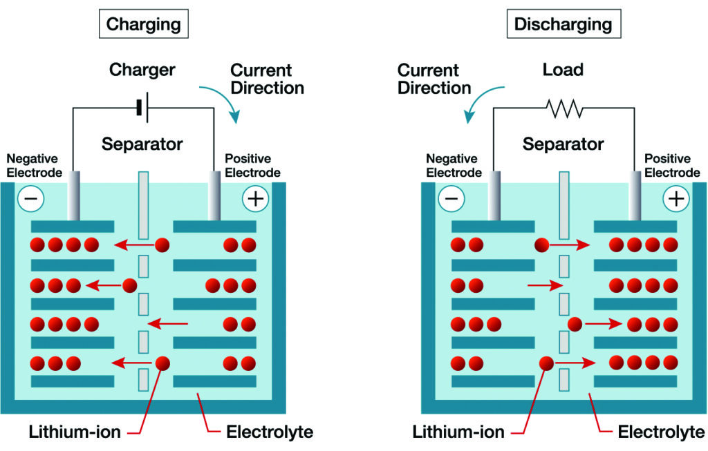
Every lithium-ion cell has a separator between the electrodes, an often overlooked but fundamental component with three key functions. The first is electrical isolation in that it must prevent physical contact and electron flow between the anode and the cathode to avoid an internal short circuit. The separator also serves as an ionic conduit, specifically permitting lithium ions to move through pores in the material between the electrodes during charging and discharging. It also has a vital safety function in lithium-ion cells in that should the cell begin to overheat, the separator can be designed to shut down the cell by closing the pores through melting of the separator material.
Material trade-offs
Various trade-offs must be managed when engineering a separator, and the behaviour of materials is central to them all. The first involves balancing thinness and mechanical strength because thinner separators increase energy density by making room for more active material within the same volume. However, thinner separators are at greater risk of tearing during winding/stacking and of being punctured by lithium dendrites.
Another key trade-off is between porosity and emergency shutdown performance. High porosity is needed for low ionic resistance and high power because the quicker the ions can get from one electrode to the other, the more power the cell will develop. The material and pore structure must also be designed to melt and close predictably.
Ensuring uniformity in pore size, shape and distribution is crucial to ensuring a consistent ion current across the entire electrode surface. At the same time, the separator must have sufficient wettability to avoid dry spots that would increase resistance.
The separator must also be dimensionally stable throughout the range of temperatures to which it will be exposed, meaning that it must not shrink, distort or melt during fast charging, for example. Ceramic coatings improve this complexity and cost.
Inside, cells are electrochemically aggressive, with a strongly reducing environment at the anode and a highly oxidising environment at the cathode, and the separator must resist both.
Material selection has huge influence on performance, safety, durability and cost. Today, most lithium-ion cells have separators made from microporous films of polyolefins such as polypropylene (PP) and polyethylene (PE).
Typically, PP films are made in a ‘dry’ process in which the film is stretched to create the pores, resulting in a microstructure with high figures for both thermal resistance and melting point (around 165 C), as well as excellent mechanical strength.
In the ‘wet’ process – the most common for EV batteries – a plasticiser is mixed with the base material (mainly PE), then extracted to create a highly uniform structure and excellent porosity, wettability and shutdown capability, with PE melting at approximately 135 C. The downside is lower figures for both mechanical strength and melting point than those of dry process alternatives.
Use of the wet process is predominant in the production of separators for EV batteries owing to its superior pore structure, more on which later. Also known as thermally induced phase separation (TIPS), the wet process is used primarily for producing PP and some PE/PP composites. At the mixing stage, the plasticiser added to the PE pellets is a liquid hydrocarbon such as paraffin oil that, along with other additives, forms a homogenous molten mixture. This is then extruded as a thin film and cooled. As the temperature drops, the TIPS process occurs, in which the polymer solidifies and the plasticiser forms liquid droplets throughout the polymer matrix. The film is then stretched in both length and width, which pulls the polymer chains straight and aligns them in a grid-like pattern. This makes the pores more uniform in size and shape, and increases both the strength and the dimensional stability of the entire structure. The plasticiser is then extracted by washing the film in a volatile solvent, leaving behind a network of pores where the plasticiser droplets once were. In the final step, the film is dried to remove any residual solvent and may be annealed to adjust the crystallinity.
Ceramic coatings are a standard enhancement, usually consisting of a layer of alumina (Al2O3) or silicon dioxide (SiO2) applied to one or both sides of the base PE or PP film. They prevent thermal shrinkage at high temperatures, thereby maintaining the separation between electrodes. Ceramic coatings also improve wettability because their particles are hydrophilic and therefore are better than the polyolefin surface at absorbing electrolyte. Furthermore, their hardness improves their resistance to dendrite penetration.
A typical separator today consists of a wet process PE film with a ceramic coating on the anode-facing side. The ability of the wet process to create a highly porous and uniform structure makes it the preferred choice for most automotive-grade battery cells. However, the superior strength achieved via the dry process leads to its use as a component in composite separators for specific high-energy applications.
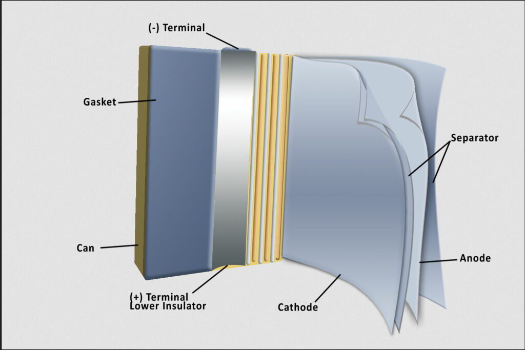
The separator keeps the anode and cathode apart and blocks electron flow while allowing ion flow. Advances are focused on precise, reliable safety shutdown and structural integrity
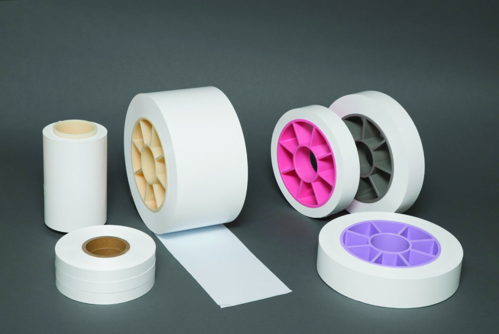
(Image: Entek)
Shutdown sandwich
One of these applications is the PP/PE/PP ‘shutdown sandwich’ – a composite separator designed for enhanced safety in high-performance cylindrical and prismatic cells. If the cell starts to overheat, the PE layer melts and its pores collapse, blocking ion flow and halting the electrochemical reaction. Meanwhile, the PP’s higher melting point and greater mechanical strength allow the outer layers to retain their structural integrity, preventing the anode and cathode from touching.
While a simpler PE separator with a ceramic coating is adequate for many cells, composite separators are important for high-performance cylindrical and prismatic cells because of the inherently greater risk from their higher energy and power densities, the demanding mechanical environment to which the separator is subjected, and the premium on safety and reliability in high-end e-mobility applications.
In a high-performance cell, any internal short circuit or thermal event will release more energy much more quickly than would a lesser cell. A separator failure can escalate into a fire or an explosion in seconds. In cylindrical cells, the jellyroll is wound under high tension during manufacture to maximise energy density, meaning that mechanical strength of the separator is essential to prevent tearing. During cycling, furthermore, anodes undergo significant expansion and contraction, pushing against the separator, so the robust PP layers in a composite separator must resist puncturing under repeated stress reversals.
High-performance prismatic cells are subjected to similar mechanical stresses. Their electrodes are stacked under pressure to ensure good contact and minimise resistance to ion flow, but they also swell during their service life because of gas generation and electrode expansion.
(Image: Asahi Kasei)
Wet and dry abuse
Cells of both formats must also withstand vibration and impact in vehicle operation. A recent study by a German team compared the performance of five commercially available separators under severe mechanical abuse in the laboratory [1]. Some examples were made using the wet process and some using the dry process – some with ceramic coatings or fillings and some with nonwoven structures.
The researchers found that the wet process, ceramic-coated PE (C/PE) separator demonstrated superior mechanical integrity, significantly delaying internal short circuits and TR, while traditional dry process polyolefin separators failed at lower loads. They stated that standard material-level tests, such as tensile and biaxial punch procedures, are insufficient predictors of cell-level safety performance, emphasising that understanding the failure mechanisms is more important.
The PP separator was a monolayer component made using the dry process. It had slit-like pores and was strong in the machine direction (MD) – the direction in which the separator base film passes through the coating machinery – but weak in the transverse direction. The tri-layer PP/PE/PP separator was also formed using the dry process, had smaller pores than the PP separator and exploited PE’s 135 C melting point as the shutdown mechanism. The third separator tested was made of PE with an Al2O3 ceramic coating and produced using the wet method. This C/PE component was equally strong in all directions (isotropic) thanks to its highly cross-linked mesh pore structure.
The final two separators were both PET parts produced using a different – ‘wet-laid’ – process and described as nonwoven. The ceramic-filled CF/PET separator contained 71% by weight of Al2O3 in the form of fine (400 nm) particles, and exhibited high thermal stability. The material used for the final separator tested (CC/PET) had a coarse (>2 μm) Al2O3 coating with an even higher ceramic content by weight (76%), which also showed high thermal stability.
Mechanical abuse testing to failure was based on crushing the cells with a hemispherical punch, and ranking their performance regarding the load and deformation they could withstand before a hard internal short circuit and thermal runaway (TR).
The wet process C/PE material was the clear winner, withstanding 33% more load and 25% greater deformation before TR compared with a separator made from pure polyolefins. The CP/E’s isotropic strength and ceramic coating prevented pore opening and electrode contact, stabilising the cell structure.
The nonwoven separators (CF/PET and CC/PET) were described as good performers, demonstrating around 17% higher load capacity than that of pure polyolefins. Despite brittle PET fibres cracking, the high ceramic content and thermal stability insulated short-circuit spots and prevented TR propagation, allowing for further deformation.
The dry process polyolefins (PP/PE/PP and PP) were the poorest performers in the crush tests, failing at the lowest loads and deformations. Under biaxial stress, their slit-like pores opened in the transverse direction, causing early internal short-circuiting. The low thermal stability then allowed these ‘soft’ short circuits to escalate rapidly into hard shorts and (TR).
Correlation of the results between the crush tests of complete cells discussed above and both tensile and punch tests of material samples was mixed. The C/PE separator’s superior cell-level performance was accurately predicted by its material tests, which revealed excellent and isotropic tensile strength and biaxial puncture resistance. However, the material-level tests were poor predictors for the other separators. The nonwoven samples (CF/PET, CC/PET) performed worst in tensile and biaxial punch tests but did well in the cell crush test, while the dry process separators (PP, PP/PE/PP) had high MD strength but performed poorly in the cell test.
Understand failure mechanisms
The main implication of this low correlation, the researchers argue, is that relying on standard material parameters (such as MD tensile strength) is misleading, and that understanding the failure mechanism (pore opening in the transverse direction or fibre cracking, for example) is crucial for assessing real-world safety.
Their analysis of the different separator materials’ impact on TR behaviour – onset time, discharge time, maximum temperature, gas emissions and mass loss – was also revealing.
The TR discharge time is the time it takes for the cell voltage to collapse from its normal value to near zero after TR has started. It is a crucial metric for understanding the violence and rate of energy release during a runaway event. Rapid voltage collapse signifies a massive, uncontrolled internal short circuit through which the cell’s electrochemical energy is dumped as heat and electric current. In this situation, exothermic chemical reactions (electrolyte decomposition, cathode breakdown, etc.) are running away, generating even more heat; thus, a shorter discharge time means that this energy release is more rapid.
With polyolefin separators, TR onset was almost instantaneous at 2–7 seconds after the first internal short circuit, while the nonwoven samples did better because their high thermal stability delayed onset for 17–19 seconds after the first short.
Separators with ceramic coatings (C/PE, CF/PET, CC/PET) extended the TR discharge time by up to 44%, indicating higher electrical resistance in the short-circuit path, which can slow energy release.
The researchers explain that ceramics help lengthen discharge times because they increase electrical resistance at the location of the internal short circuit, even under the high pressure of a crush test, acting as insulating spacers, even as the polymer base (PE or PET) fails. The inert, non-conductive ceramic particles physically keep the anode and cathode apart. They also ensure that the short is less efficient by making the current path more tortuous with higher resistance, which limits current flow and slows the rate of electrochemical energy release. By slowing the electrical discharge, they also slow the initial heating, which in turn slows the subsequent chemical reactions.
In engineering battery packs, cells with longer TR discharge times are highly desirable because failing cells are less likely to set off their neighbours, they give safety systems a better chance to work as designed and the overall hazard severity of a single cell failure is reduced.
The researchers also measured peak surface temperature (PST) during the TR events they triggered. PST is a direct consequence of the total heat released from the cell and its rate of release, serving as a proxy for the violence and severity of the internal failure. A higher PST directly increases the heat flux to adjacent cells, making it much more likely that neighbouring cells will be heated past their own thermal stability thresholds, initiating their own TR.
Ceramics also limited PST for the same reasons that they increased discharge times, and cells with ceramic coated separators reached lower PSTs (around 456–469 C) than those with pure polyolefin separators (about 493–506 C). At pack level, designers use these data to model heat transfer and design cooling systems, thermal barriers and spacing between cells to withstand these temperatures and prevent propagation.
Gas emissions are also affected by the separator material and have major safety implications. Pure polyolefin separators were found associated with double the concentrations of carbon monoxide (CO) and hydrocarbons compared with the nonwoven materials.
Mass loss is measured to gauge the severity of a failure by quantifying the material ejected from the cell during TR, to which all cell components contribute. The liquid electrolyte consisting of salts and solvents vaporises and is violently vented out of the cell. Exothermic reactions decompose the electrolyte, electrodes and separator into gases such as CO, CO2, H2 and hydrocarbons. Solid matter is also ejected in the form of tiny particles of electrode active materials, and metal fragments from the current collectors and other cell components are expelled with the venting gases.
Using thermogravimetric analysis, the researchers found that almost the entire mass of a PP/PE/PP separator (with no ceramics) can decompose and contribute to mass loss. With a C/PE separator (33% ceramic), however, a significant portion of its mass is inert, while the CF/PET and CC/PET separators (71–76% ceramic) are mostly inert and the bulk of their mass remains behind as ash inside the cell carcass.
The amount of mass a cell loses during TR is a crucial parameter in battery pack safety engineering because more mass lost means more hazardous material released into the battery pack or environment. A design that consistently shows lower mass loss under abuse conditions is safer.
Emerging innovations are focused on enabling next-generation chemistries, such as silicon anodes and solid-state electrolytes, along with faster charging.
One direction of research and development focuses on the use of very strong materials such as aramid fibres in composite separators. Aramid is a very strong and thermally stable material, which has a melting point above 500 C and the ability to resist shrinking and retain its structural integrity above 400 C, allowing for even thinner separators without sacrificing safety. These features are crucial for high-energy-density cells with dendrite-prone chemistries, but r&d effort centred on aramid in several forms is ongoing to overcome limitations.
(Image: Hahn et al)
Aramid and clay
For example, a group of Chinese researchers recently reported on their work on the combination of aramid nanofibres (ANFs) and montmorillonite (MMT) clay in a composite separator [2].
While correcting the problems exhibited by conventional commercial polyolefin (PE/PP) separators, namely the poor thermal stability, limited wettability and lack of dendrite suppression, earlier ANF-based separators have had problems of their own. The first of these is excessive density. Strong hydrogen bonds form between the nanofibres during membrane formation, leading to low porosity, and the dense packing hides the functional groups that help transport lithium ions, so ionic conductivity is poor. Cycle life also suffers, as exemplified by the 47% capacity retention after just 50 cycles.
The researchers’ composite separator made from ANFs and MMT clay is designed to overcome these problems with the complementary strengths of these very different materials. The ANFs serve as a structural scaffold with exceptional thermal stability, mechanical strength and electrochemical stability. The MMT clay, which is an inexpensive and abundant material, serves as a functional filler, improving porosity by creating a better pore structure for ion flow. It further enhances lithium-ion transport through its layered structure and negative electric charge, which provide pathways and help dissociate Li+ ions, boosting ionic conductivity. It also suppresses dendrite growth and acts as a flame retardant.
Both ANFs and MMT clay play crucial and complementary roles in suppressing lithium dendrites, attacking the problem from different angles. ANFs are analogous to a nanoscale version of the material in bulletproof vests, providing a robust mechanical barrier that physically blocks the sharp, protruding dendrite tips, preventing them from growing through the separator and reaching the cathode.
The MMT clay works on an electrochemical level to create conditions that are less favourable for dendrite formation, which it does through two mechanisms. The first is homogenisation of lithium-ion flux. The researchers explain that MMT has a high cation exchange capacity and a negatively charged surface; properties that allow it to adsorb and release Li+ ions, effectively helping to distribute the ion flow more evenly across the anode surface. This is important because dendrites form when the Li+ flux is uneven, preferentially depositing on hotspots. By homogenising this flux, MMT promotes smooth, uniform lithium intercalation and inhibits the conditions that lead to dendritic lithium plating.
MMT’s second dendrite-suppressing mechanism flows from the first, in that that the material’s layered structure naturally creates nanochannels and interfaces that serve as ordered pathways that enable the smooth flow of ions.
The researchers published results of electrochemical performance and lifecycle, safety and mechanical strength, indicating the benefits of an ANF/MMT separator.
Electrochemical testing was performed on a ‘half-cell’ consisting of an LFP (lithium iron phosphate) cathode, the separator (and electrolyte) and a stable standardised pure lithium metal reference electrode. Use of such half-cells is standard practice in battery r&d, with the reference electrode eliminating the complexity of a capacity-matched anode and an inexhaustible ion source/sink. The researchers reported that the half-cell retained 92.5% of its capacity after 300 cycles, significantly outperforming a baseline cell containing a commercially available tri-layer (PP/PE/PP) separator, which retained 87.04% of its original capacity.
In the safety test, a pouch ‘battery’ (strictly a cell) with an ANF/MMT separator was heated continuously from the outside to failure. It took 68 seconds longer to ignite than the control cell subjected to the same test. This delayed ignition time provides a crucial window of time between the onset of ‘abuse’ and a potential fire.
The mechanical test was one of tensile strength, measured at around 28.17 MPa, which makes it robust enough to resist penetration by dendrites.
Because it solves the porosity problem of ANFs with the integration of MMT clay, combines excellent thermal stability, mechanical strength and high ionic conductivity, all while enhancing safety though delayed ignition, it is a promising candidate for next-generation lithium-ion batteries.
The most advanced separators available today combine highly mechanically robust and thermally stable structures with shutdown membranes engineered to activate at precise temperatures, providing a more reliable and sharper shutdown response, representing multilayered, redundant safety. The PP/PE/PP tri-layer separator discussed above has become the established standard, while those that also include ceramic coatings are regarded as the state of the art and represent current best practice.
Several more advanced concepts are under investigation in the category of shutdown-functionalised nonwoven separators. For example, nonwoven meta-aramid or polyimide materials provide very high thermal stability (withstanding more than 400 C), and researchers are working on integrating a shutdown component into this kind of matrix. One candidate is thermo-responsive spheres embedded within the nonwoven structure that expand when they reach a precise temperature.
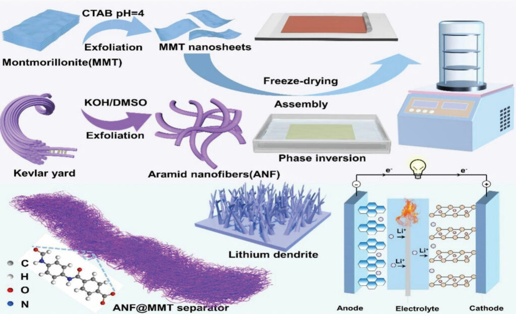
A combination of aramid nanofibres (ANFs) and montmorillonite (MMT) clay: the first serving as a thermally stable structural scaffold and the second as an ion flow improver
(Image: Cheng et al)
Melting microspheres
An example of this approach is found in a patent by another Chinese team, whose separator is based on a polyolefin substrate with thickness of 10–20 μm and porosity of 30–50% [3]. This has two coatings applied. The first coating contains ceramic particles, such as Al2O3, and nanofibres of either boron nitride or cellulose, providing heat resistance and support. The second contains temperature-sensitive microspheres made from a polymer such as PE or ethylene vinyl acetate with a low melting point.
The first coating is applied closer to the substrate than the second, which forms the outer layer, on at least one side of the substrate’s surface. The other side can be coated with either or both coatings. This layered structure avoids performance trade-offs associated with single mixed layers, enabling both fast response and high heat resistance. The nanofibres are 1–4 μm long, the optimum length to form a network, while ceramic particles fill the gaps. This enhances coating integrity, mechanical strength and thermal stability. The microspheres are 0.5–3.0 μm in diameter and melt at 80–130 C.
Samples of coated separator materials were subjected to air permeability tests before and after 3 minutes exposure to the temperature of 130 C to measure the effectiveness of pore closure, and a thermal shrinkage test after exposure to the temperature of 180 C for 1 hour to check whether the separator could maintain its structure and prevent the anode and cathode from touching, even after melting of the shutdown layer. Shrinkage is measured in the MD – the direction in which the separator base film passes through the coating machinery. The film is stretched to strengthen it during the process, but is then prone to shrinkage through thermal relaxation when overheated, so the less it stretches during an overheat test the better.
The tests were carried out on four samples with coatings of different compositions and structures, but with the same set of ingredients.
Air permeability was measured using a standardised test, in which the number of seconds required for 100 mL (s/100mL) of air to pass through a sample with area of 6.45 cm2 was recorded.
Sample 1 had an asymmetric, double-sided coating with the first coating on both sides and the second on one side only, giving a total thickness of 16 μm. Its initial air permeability, measured at 226 s/100mL, increased to 5500 s/100mL after the 130 C overheating event, indicating effective pore blockage (shutdown). After the severe 180 C overheat test, sample 1 had shrunk by only 2.8% – a very good result. With the shutdown coating on one side only, the shutdown performance of sample 1 was directionally biased, responding faster to heat coming from the side with the second coating.
Sample 2 had a symmetric, double-sided coating with the first and second coatings on both sides and total thickness of 17 μm. Its initial air permeability was already slightly less than that of sample 1, at 257 s/100mL, but its post-heating pore blockage put that figure up to 6894 s/100mL and its shrinkage after the severe overheat was identical. With both coatings on both sides, the shutdown performance of sample 2 was symmetrical and marginally more effective.
These were compared with two more samples: one with a single blended coating containing all components on one side of the separator and with total thickness of 16 μm, and another with a ceramic and nanofibre coating on one side and the polymer microspheres on the other, with the same total thickness. At 198 and 215 s/100mL for the first and second samples, respectively, both had slightly greater air permeability before the tests, but neither performed as well in the shutdown test (1568 and 2375 s/100mL, respectively) and both shrank more (46% and 18.3%, respectively).
The performance differences between separators made of the same materials highlight the importance of a symmetrical layer structure for the coatings.
These are just a few of the more promising directions in separator r&d for lithium-ion batteries with liquid electrolytes. In solid-state batteries, the functions of separator and electrolyte merge, but that is another story.

A Chinese team [2] showed that a symmetrical layer structure of coatings – one of ceramic particles and nanofibres and the other of temperature-sensitive polymer microspheres – combined precise shutdown performance with minimal shrinkage in overheat tests
(Image: Li et al)
References:
[1] Hahn, A., Ruf, M., Doose, S. and Kwade, A., “Enhancing Lithium-Ion Battery Safety: A Comparative Study of Separator Performance Under Mechanical Abuse”, Future Batteries, vol 6, p 100064, 2025. doi: 10.1016/j.fub.2025.100064.
[2] Cheng, L., Zhang, X., Cao, Y., Han, L., Kan, Y. and Hu, Y., “A High Thermostability Separator Inhibiting the Growing of Li Dendrites for Interfacially Stable Lithium-Ion Batteries”, Composites Communications, vol 49, Feb 2024, Art. no. 101936, doi: 10.1016/j.coco.2024.101936.
[3] Li, Z., Xiong, D. and Zhang, H.,
“Battery Separator and Secondary Battery”, Chinese Patent CN 117438747 A, Jan 23, 2024.
Some suppliers of battery separator materials
Almatis
Caplinq
Celgard
Entek
Freudenberg Performance Materials
GVS
Pall
Polymer Films
Semcorp
Senior Europe
Sepion Technologies
Tekra
Toray Industries
Click here to read the latest issue of E-Mobility Engineering.
ONLINE PARTNERS
