


Battery Safety

(Courtesy of Polestar)
Cut-off points
The EV battery industry offers a variety of ways to minimise the hazards they can pose, as Peter Donaldson explains.
Proximity to large amounts of energy has always presented hazards, but people have mostly learned to live with them and enjoy its benefits. However, being close to a high-energy electrochemical system such as a 100 kWh battery is still relatively novel. What’s more, a series of high-profile EV battery fires, vehicle recalls prompted by fire risks and the new Chinese government rule mandating 5 minutes’ warning between detecting an incipient thermal runaway and penetration of the passenger compartment by fire to give passengers time to escape have sharpened the focus on battery safety, even though such events are rare.
For obvious reasons, batteries are made from non-flammable materials as far as possible, and their electronic control and thermal management systems provide increasingly tight regulation of operating conditions. Generally conservative design and over-engineering, stringent cell material purity standards, venting and redundant heat transfer pathways all help with reliability and safety.
However, high-energy lithium-ion batteries present electrical, chemical and thermal hazards. Electrical potentials in the 400-800 V range are typical for modern EVs, and with the associated large currents they can induce fatal shocks and arc-flash events if mishandled.
Any breach in the isolation that separates high-voltage circuits from their low-voltage counterparts or other parts of the vehicle is also dangerous. Furthermore, cells contain flammable electrolytes and must be protected against thermal runaway, which is a self-propagating reaction.
Causes of cell failures include overcharging, external heating and external short-circuits, while internal causes include contamination of cell materials, separator failure and dendrite formation. These latter two can cause internal short-circuits by directly connecting the anode to the cathode, for example.
Thermal runaway is the most hazardous consequence of a cell failure, because temperature increases to a level at which it promotes reactions that generate even more heat – more than can be safely dissipated. This can propagate to adjacent cells, starting a cascade effect that can result in fire and explosion.
Industry is working on the assumption that the new Chinese rule is likely to trigger similar approaches from authorities in the EU, the US and other major EV markets. Several cell OEMs and integrators have already made changes to meet such regulations, incorporating directed vents and high-impedance cathodes, for example, along with pack designs that allow for quick disconnection or de-energising individual cells using thermal shunts or voltage-based isolation.
The self-generating nature of a thermal runaway results from the chemical compositions of the cathode and the electrolyte. Most lithium-ion batteries liberate oxygen when they go into a failure mode, a battery testing expert points out. The cathode is made from a lithium metal oxide that decomposes when it gets too hot, releasing gaseous oxygen as the oxide compound breaks up, and even though the electrolyte itself is fairly benign, the solvent is a volatile hydrocarbon.
Generating its own oxygen and fuel, therefore, a burning lithium-ion battery is difficult to extinguish, so much design effort goes into everything from cell construction to electrical control, thermal management and emergency cut-out systems. Safety mechanisms are integrated at cell, module and pack levels, and apply to everything from the design and construction of individual cells to battery cases. They include features such as single-cell fuse systems, integral firefighting systems and sensor/software approaches such as continuous temperature tracking.
One approach is to limit the capacity of individual cells so that there is less energy to release, and vents can be included to relieve pressure within the cell casing.
Other automatic safety precautions typically integrated into cells include a means of temporarily or permanently cutting off the flow of electricity. Non reversible current interrupt devices are often pressure-activated, while reversible types include positive temperature coefficient thermistors, whose resistance increases with temperature. There are also shutdown separators, which melt at specific temperatures to stop the flow of ions through the electrolyte, and ceramic separators between the anode and cathode to improve thermal stability.
At the module level, the temperatures and voltages of all the cells are monitored, with fuses incorporated for non-reversible current interruption. Between the cells, typically, spacers minimise heat transfer from one to the next, along with thermal barriers around modules to protect their neighbours.
At the pack level, the battery management system (BMS) monitors the electrical properties and temperatures of all the cells, controls the thermal management system to keep the battery in its ideal temperature range and can shut down cells and modules if limits are exceeded and then warn the driver.
There are also more fuses, including impact-sensor-activated pyrofuses, which are circuit breakers that can be activated by the same kinds of inertial sensors that trigger airbags for example, and which cut off the current permanently. There are also pack level vents to prevent the build-up of hot, high-pressure gases inside, and thermal protection mats for insulation between the modules and the outer casing.
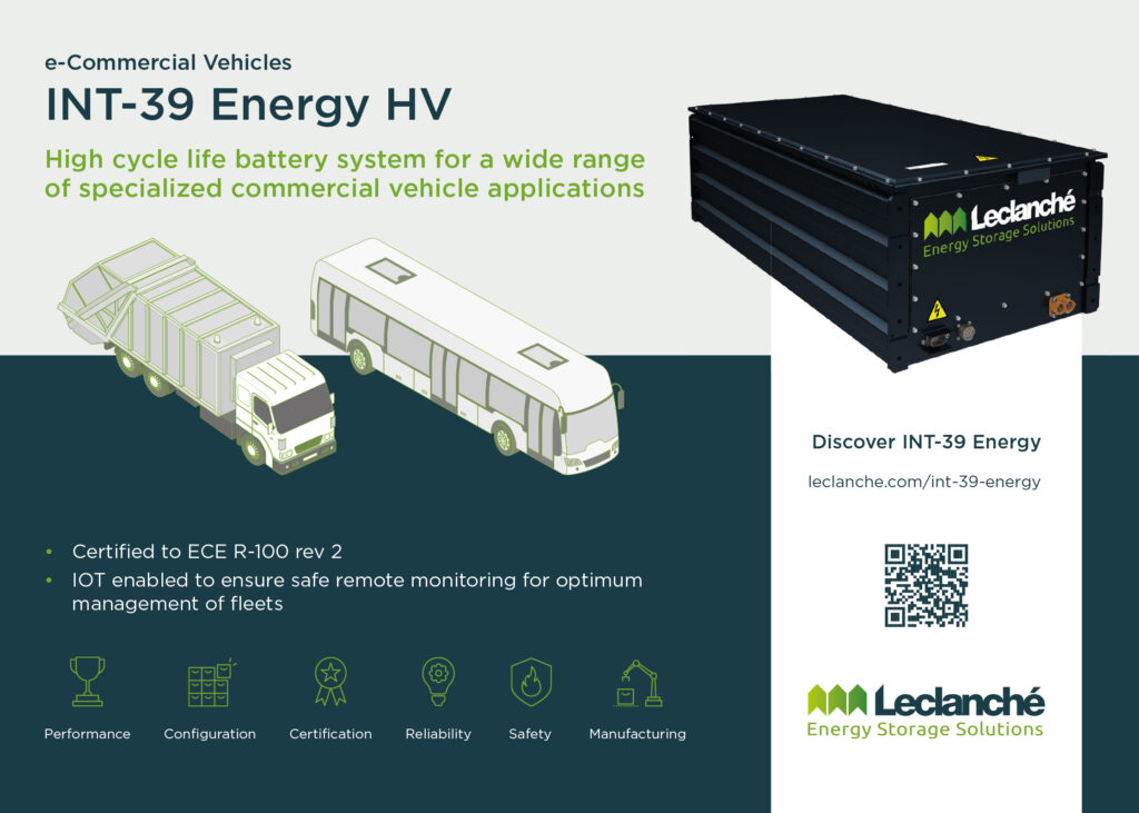
(Courtesy of Leclanche)
Cell form factor effects
The form factor of cells has an important effect on the rate at which they can be cooled or heated, much of which is down to the ratio of surface area to volume. Of the three main form factors used in EV batteries – cylindrical, prismatic and pouch – the first has the smallest ratio and is consequently the slowest to release or absorb a given amount of heat energy.
Both prismatic and pouch cells tend to be thin, flat and rectangular, giving them much higher ratios. Pouch cells also have thin Mylar walls that present less thermal resistance than the aluminium cases of prismatic cells.
Pack design reflects the philosophies of battery suppliers and EV manufacturers, with some preferring cylindrical cells with active cooling while others choose not to provide it, so there is no single way to adapt battery packs to meet the 5-minute escape requirement, says one battery developer, which tackles the problem using a combination of advanced software and sensing.
One approach to managing unwanted thermal propagation in cylindrical cells is to form a cell support structure from a phase-change composite material made of graphite and a substance that melts to absorb excess heat, and then solidifies as it cools, in a repeatable cycle.

Mitigating propagation
Over the past 10 years, a heat-spreading material specialist notes, the battery industry has come to use four main methods of stopping or mitigating runaway thermal propagation. These are encapsulation in a fireproof box, adding insulation material between cells, immersion in a dielectric cooling fluid, and putting heat-spreading materials in close contact with individual cells.
Encapsulation is the quickest and cheapest way to meet the 5-minute occupant escape window requirement, but is the least satisfactory for thermal management. Similarly, insulation can prevent a failed cell’s neighbours from reaching a critical temperature, but it adds bulk and can limit fast charging and/or life. Some batteries also incorporate internal cross-members to isolate individual modules, at the cost of packaging volume and energy density. However, careful cell/pack design and selection of thermal barrier materials mitigate this.
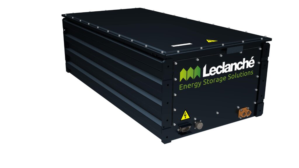
For example, flexible aerogels originally developed for use in the petrochemical refining and thermal power industries are successfully applied as thin-layer cell-to-cell and module-to-pack thermal barriers.
Aerogels are solids derived from gels in which the liquid component of the gel has been replaced by air, an efficient insulator.
As well as providing sufficient thermal resistance throughout the cell’s normal life cycle, aerogels also resist degradation during thermal runaways, and can be flexible enough to accommodate changes in cell dimensions as they charge and discharge, as well as enlarge with ageing.
One aerogel provider notes that cell-face pressures caused by their expansion can reach 400 kPa in pouch types at the end of their service lives, and up to 2 MPa for prismatic cells, and that aerogels must compress but still retain their thermal resistance. They also stand up to mechanical shock in normal driving and are light and thin enough not to reduce energy density significantly.
The third method for mitigating unwanted heat propagation, immersion cooling in a dielectric liquid, is seen as the ultimate in all-round thermal management. However, it comes at the cost of complexity in the cooling system along with the cost and environmental issues associated with some of the liquids.
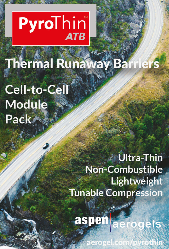
The final method, thermal spreading, can be used in combination with other methods and with thermal interface materials (TIMs). While a TIM would typically be a 2 or 3 mm layer connecting a cell or module base to a cold plate, a thermal-spreading material such as aluminium or graphite is placed between the cells in close contact with their walls, from where it conducts heat down to the TIM layer and to the cold plate.
Graphite is electrically conductive, as is aluminium, so there is a thin dielectric layer preventing direct contact with the cell wall. Aluminium has some benefits in that it provides structural support, but at 200 W/mK its thermal conductivity is fairly low.
When a cell catches fire, the temperature inside it rises to 600- 700 C for about a minute, so the heat spreader, the cold plate and the intercell insulation together have to channel enough of the heat away to prevent runaway propagation to the next cell.
By happy coincidence, our heat spreading specialist says, once the thermal management solution is robust enough to take care of such a thermal event, it is more than adequate in normal use for fast charging and discharging, and for creating an even thermal gradient across the cells to improve life.
(Courtesy of Audi)
Electrical safety
Electrical safety depends to a large degree on the ability to isolate the battery and the entire high-voltage circuit, with different solutions for different situations, one battery developer says.
In normal operation the main contactor relays are used, and there are additional plugs known as service disconnect devices that are used in maintenance and disposal. The main fuse breaks the circuit in the event of an over-current or short-circuit, while pyrofuses are triggered in more severe cases such as crashes, fires or abuse.
Equally important is the high-voltage interlock loop (HVIL), which uses low-voltage signals to monitor the integrity of high-voltage circuits and their isolation from the low-voltage ones, the battery housing and the vehicle chassis. It runs alongside the high-voltage circuit through every component and connector, and any break in it results in the high-voltage battery opening the main contactors.
In communication with the BMS, components including the traction inverter, DC-DC converter and onboard charger also monitor the HVIL current, and if any error is detected they start a failsafe turn-off sequence.
An isolation monitoring device measures the resistance between the high-voltage bus and the parts from which it must be isolated, particularly the low-voltage bus and the vehicle chassis, against a required minimum value, typically 500 Ω/V. If the resistance falls below that threshold, the battery is prevented from connecting to the drive system or, if the vehicle is moving, power is reduced to a minimum.
EVs also feed a crash signal into the system to shut down all the high voltage circuits in the event of an accident, and a disconnect switch must always be accessible to first responders. It is, however, hard to guarantee that such disconnects can always be reached regardless of the position of and damage to a crashed vehicle, which makes automatic operation essential.
Pyrofuses are relatively new devices, and there is no mandatory requirement to fit them, as the regulations simply require the vehicle to be made electrically safe and leave it up to the manufacturer how to achieve that. The technology is still under development, with manufacturers working on their ability to handle higher voltages and currents.
One battery developer tells us it is working on 800 V devices, and is cooperating with academia to develop a reliable means of disconnection between battery packs. The company says most regulations require these fuses to be fitted in a unit outside the battery to ease access for replacement.
However, confidence in HVIL and emergency disconnect systems s high, one of our testing experts reports, emphasising that the approach to isolating high voltage is well understood in engineering terms and that the technology is reliable.
This specialist’s organisation develops battery packs for customers and also tests third-party packs, and therefore has a good view of any issues. He says the company has had no incidents of high voltage not being properly isolated but has had thermal events, which are much harder to prevent.

Post-crash safety
Crash safety is considered in almost all the standards that relate to battery testing, such as ECE R100, GB38031, SAE J2464/J2929 and ISO 12405.
R100 testing for EVs, for example, stipulates that the system must come to a safe voltage within 60 seconds after a crash, although one testing expert points out that it is a self-certifying standard on the part of the vehicle OEM and could be more robust if compliance had to be independently verified. R100 also takes battery housing deformation into consideration.
EVs designers face the challenge of ensuring that the dense mass of the battery pack does not cause any crashworthiness issues, the expert says, adding that more EV-specific crash test requirements are probably needed to take this into account.
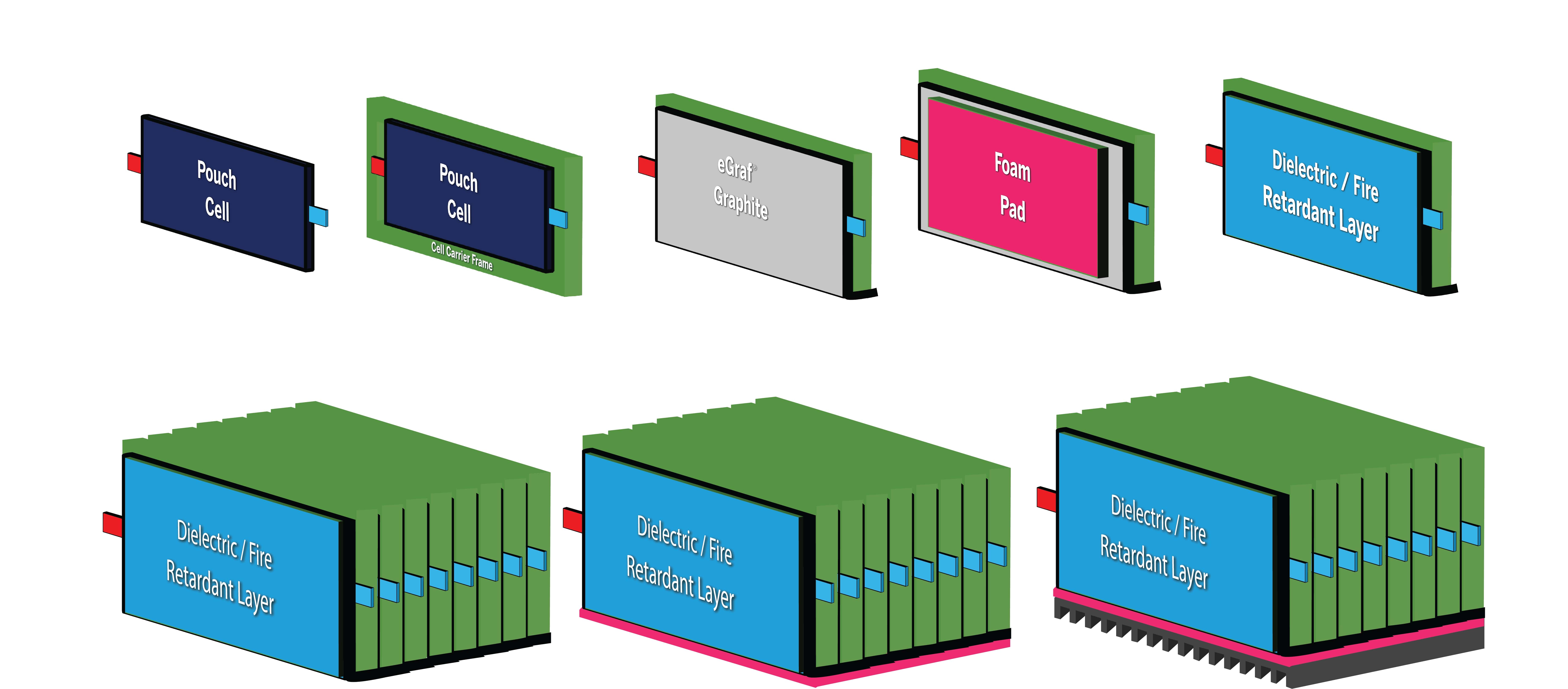
(Courtesy of NeoGraf Solutions)
While EV manufacturers avoid placing any part of the battery system in a vehicle’s crumple zone, the increasingly common ‘skateboard’ EV platform architecture brings the long sides of the battery pack close to the outer edges of the vehicle, an arrangement that might seem to make the pack vulnerable to side impacts. China’s particularly severe GB/T crush requirement subjects battery packs to a 100 kN side pole test, a materials specialist points out, influencing EV designs to have the vehicle structure attenuate crash loads early before transmitting them to the battery enclosure.
However, that is the kind of issue that tends to be caught early in the vehicle design process and corrected in simulations before real hardware is built and tested, a testing expert points out.
Crash-related safety problems that slip through to production vehicles tend to be more subtle than that. For example, General Motors’ early Chevrolet Volts sometimes burst into flames about a fortnight after a crash test because coolant ingress had compromised battery isolation.
Because the aftermath of a collision with an IC-engined vehicle could expose an EV’s battery to burning fuel, most EV safety standards such as UL 2580 and ISO 6469-1, and the United Nations’ GTR and ECE regulations, have an external fire exposure requirement, with a test to prove that it presents no explosion hazard.
External and internal fire protection
The battery pack’s ability to withstand external fires depends on the combination of enclosure materials, coatings, insulation and heat spreading. Most enclosures are steel or aluminium (although polymer composite cases are under development) and, along with interfaces such as sockets, they are typically protected by flame retardants. Also, thermal insulation is enhanced by incorporating air gaps or insulation mats between the cells/modules and the housing.
A materials specialist we consulted says material selection will be impacted by new tests for thermal runaway and external fires which mandate that they withstand 900 C for 5 minutes, potentially ruling out traditional materials such as sheet moulding compound and aluminium.

Designs are evaluated using fire resistance tests in standards such as ECE R100 Annex 8E.
The chemicals industry is working on advanced materials that can form ‘intumescent’ coatings, which are thin under normal conditions but expand to increase their protective properties in a fire. Applied as layers typically between 0.3 and 1.2 mm deep, they first soften when exposed to extreme heat and then expand due to the release of gas from their component pigments.
An outer expansion layer then solidifies due to the carbonisation of the pigments’ organic components, while the remaining inorganic components preserve the expanded coating’s mechanical strength. The coating expands to between five and 50 times its original thickness, and contains insulating air cavities, a coatings expert explains.
For example, with lower energy density chemistries, such as lithium iron phosphate, one intumescent coating protects from external fires as hot as 1000 C. A low-viscosity material, it is applied to the outside of the case, particularly the top cover as most of a battery fire goes upwards in the thermal runaway, and preventing lids from softening or melting is a primary goal.
In tests, an aluminium panel with a 150-micron layer withstood a 1000 C fire for more than 5 minutes while keeping the temperature on the reverse side below 350 C, the expert reports.
The same company also makes coatings that can be applied inside battery packs, sprayed on the underside of pack lids for example, and which can adapt to complex shapes within the pack, making them suitable for volume production. These coatings can withstand temperatures of up to 1500 C and can, for example, prevent the explosion of NCM 811 cells in a thermal runway.
Materials such as graphite can be used to mitigate the effects of internal as well as external fires, our heat-spreading expert says. A burning cell can be considered a point heat source, and if the energy released can be spread though the pack by the graphite while the cell’s immediate neighbours are protected from the concentrated temperature by insulation, then the progress of the fire is slowed and the escape time is extended.
He notes that all his customers so far have wanted to mitigate heat moving from the inside out, but the material would work the same way to protect battery internals from heat moving in the opposite direction.
The application of such materials provides time for firefighters to extinguish the external fire and prevent a battery fire, or at least slow its progress sufficiently for people to get out of the vehicle.
(Courtesy of Webasto)
First-responder safety
The safety of first responders is as important as that of the vehicle’s occupants. While EVs and their battery casings are designed to prevent any penetration of the pack that disrupts the cells in a crash, that is not always possible and the HVIL cannot eliminate the resulting hazards.
What’s more, it remains difficult for first responders and recovery personnel to be certain of the battery’s status if the vehicle is not functional, a testing expert points out. Naturally, they need to know whether it is about to catch fire or is leaking hazardous chemicals, and that has not yet been addressed by legislation or industry, he says.
A possible solution, he suggests, is some kind of common BMS output that would provide battery status information, ideally via wireless comms or some quick and easy way to plug in to the vehicle. He reports that there has been discussion of an open CAN standard that would allow anyone in that position to check battery status quickly.
In motorsport, vehicles are fitted with prominent battery status indicator lights, and there are other possible solutions, but there is no legislation yet for road vehicles that calls for such systems. Also, there is a hesitancy in industry to commit to any particular solution that would require significant investment if there is a risk that subsequent legislation would mandate a different one, he cautions.
Stranded energy, where electrical energy remains in a battery without a means of removing it, presents a potential danger to first responders. According to one expert, the industry, research institutes and others continue to look for practical solutions that can be built into battery systems. Meanwhile, the primary approach to the problem has been through training first responders by using mechanisms developed by the US National Fire Protection Association, for example.
Current practice includes dousing a crashed vehicle with water to keep the battery below its critical temperature, trying to concentrate the hoses on the battery case if it is accessible and even lifting entire vehicles into vats of saltwater carried to the scene by trucks. Making it easier to get water into the pack might help, a testing expert suggests, by means of a port into which a firefighter could plug a hose for example.
Others argue that lithium-ion fires should be put out with foam, CO2 , dry chemical dust, powdered graphite, copper powder or sodium carbonate, water being used only to prevent the fire from spreading. If the fire proves impossible to extinguish, the pack should be allowed to burn out in a controlled and safe manner.
Cell design is improving to make re-ignition less likely in future battery systems. For example, the impact of stranded energy can be further mitigated by better cell- and battery level venting systems that allow hot gases to escape in a controlled manner, as heat extraction is important to prevent re-ignition.
Inside the cell itself, better separator technology and the eventual transition to solid-state cells without liquid electrolyte are promising directions of development. Meanwhile, one focus of improvement in liquid electrolytes is the use of additives to reduce or contain the risk of thermal propagation and fire.
The primary focus of EV battery technology development has been on energy density and cost, with safety an obviously important but secondary consideration, argues one of our testing experts. To support this contention, he points to the use of lithium titanate cell chemistry in military applications because it does not go into thermal runaway, even when damaged by gunfire. It is, however, heavier and more expensive than other lithium-ion chemistries such as NMC and lithium iron phosphate.
(Courtesy of Horiba Mira)
Predictive battery management
Almost regardless of battery configuration, cell type and the combination of thermal management, runaway mitigation techniques and electrical safety features, the BMS plays a critical role in battery safety, with one testing expert calling it the first line of defence.
A BMS monitors multiple parameters, and should also be able to provide a history of the battery’s operating life and adjust parameters to maintain safety. Most EV manufacturers use over-the-air (OTA) monitoring via comms systems that can also support remote updates.
The expert’s testing organisation has been examining the effects of ageing on the battery and the prediction of unwanted lithium plating and the dendrites that grow from it, for example, because that can increase the chances of a thermal propagation event. It is therefore advocating the use of crowdsourced BMS information and more realistic models of battery cells to improve understanding of what is happening inside batteries. However, much of the process is not measurable directly, and measurements such as increases in temperature or changes in resistance may come too late.
The company’s alternative approach is detailed modelling of batteries combined with monitoring of data, with the goal of making accurate predictions. Updates could then enable the BMS to change the way it manages the battery to slow or stop a trend towards failure. While different battery configurations and cell chemistries complicate the picture, the combination of OTA monitoring and predictive algorithms is promising.

(Courtesy of Millbrook)
Safety and ‘abuse’ testing
A deep understanding of battery designs through rigorous testing, adherence to automotive standards and constant analysis in the context of specific vehicle applications is key to improving safety, one developer says. They are often split into ‘safety’ and ‘abuse’ tests, the latter being associated with tests that go beyond normal operating conditions or deliberately causing damage, although one of our experts considers them all to be safety tests because of the need to understand what can happen in extreme but plausible circumstances.
Testing is carried out at cell, module, pack and ultimately vehicle levels, with the cost and stakes involved being higher at each stage. The main groups of tests relate to safety in transit by air, sea, rail and road, as lithiumion batteries are designated Class 9 hazardous materials, and those that relate to use in vehicles.
Vehicle applications are governed by UNECE R100, for example, which covers road-going vehicles with four or more wheels and requires a thermal test that cycles through low and high temperatures including a significant over-temperature plus tests for vibration, shock, short-circuit, overcharge, over-discharge, crushing and fire resistance.
Meanwhile the UN 38.3 regime, which covers the safety of batteries when transported by air, sea, rail and road, mandates many of the same kinds of tests but with different parameters, and adds others such as an altitude test for carriage by aircraft.
Conducting such testing, particularly on high-capacity battery packs, demands a wide variety of facilities and equipment, preferably spread over a sizeable area to provide large safety zones and reliable containment of potential fires and explosions, the expert points out. While some are general facilities in which many different kinds of tests can be carried out, others are more specialised.
For example, one testing organisation has a facility designed to emulate a situation that might follow a crash between an EV and a IC-engined vehicle, in which spilled fuel flows under the EV and ignites. The rig used for this test includes a shallow pan similar in size to the battery pack that is filled with petrol, ignited remotely and moved underneath the pack by a winch system, left in place for a set time and then pulled out.
Other, more general facilities provide safe areas in which different types of test equipment can be connected. To induce an external short-circuit, for example, a high current-capacity, low resistance switch is connected between the battery’s main positive and negative terminals and activated electronically.

Our expert notes that this kind of test tends to by quite boring, as the pack’s internal fuse blows as designed and the only evidence that anything has happened is a short spike in current and a sudden fall in voltage to zero. He adds that things can get more interesting in cell-level tests because typical automotive cells don’t have individual fuses, although that is changing.
Some tests address thermal runaway directly. Under the UL 2850 standard, another expert explains, the battery system must be fully charged for the test and a centrally mounted cell heated until runaway or it is forced into runaway within 10 minutes by any means necessary. Once the runaway is initiated, the mechanism used to create it must be withdrawn. For the battery to pass the test, there must be no explosion that results in ‘projectiles’ falling outside a circular inner perimeter.
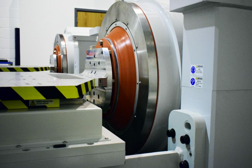
The UNECE R100 rules also include a standard load profile for the shock a battery pack would see in a typical car crash, and manufacturers can also request test pulses specific to their vehicles obtained from their own vehicle-level crash tests or through simulation. Depending on the size of the pack, either a sled or a full vehicle crash facility can be used for the test, either of which can generate a shock with a precisely calibrated time versus acceleration profile. In the latter case, the pack is typically mounted on a wheeled trolley and pulled into the obstacle by a winch.
Other safety-related tests include electromagnetic compatibility to make sure that driving past a powerful radio transmitter for example would not induce dangerous currents in any part of the system.
While the EV industry is still fairly young, the effort going into understanding the behaviour of batteries in extreme situations bodes well for the safety of existing and future EVs, despite the amounts of energy modern systems store and the complexity of the chemistry involved.
Acknowledgements
The author would like to thank Ken Boyce at UL Energy & Industrial Automation, Isidor Buchmann at Cadex Electronics, Greg Harris at Horiba Mira, Peter Miller and Alexandra Mulot at Millbrook, Ramesh Natarajan at Webasto, Shriram Santhanagopalan at the NREL Center for Integrated Mobility Sciences, Christian Theeck at TUV SUD Battery Testing, Brett Trimmer at NeoGraf, Tunji Adebusuyi, Pierre Blanc and Sylvain Chonavel at Leclanche, John Williams at Aspen Aerogels, Pascal Soergel at Voltlabor and Mark Wright at Solvay Specialty Polymers & Thermoplastic Composites for their help with researching this article.

ONLINE PARTNERS

