


Battery safety

(Image: MG)
As safe as Swiss cheese?
Peter Donaldson samples the many layers of defence involved in ensuring battery safety
Lithium-ion batteries present a fundamental engineering trade-off. The technology offers the high energy density that makes e-mobility possible, yet it contains inherent chemical instability – to varying degrees depending on chemistry – that, when triggered, can unleash a self-sustaining cascade of heat, gas and fire. This phenomenon is known as thermal runaway, and preventing it has become the single most critical safety challenge in battery pack design.
For years, the industry has relied on a layered defence model, often compared to slices of Swiss cheese. In this model, no single barrier is perfect; safety emerges when the holes in one layer are covered by the strengths of another. The approach is sound, but it has historically suffered from a lack of specificity. Which holes exist? Which technologies plug which holes? And crucially, as battery architectures evolve toward cell-to-pack (CTP), structural batteries, and higher energy densities, where are new holes appearing?
Here, we address those questions by drawing on technical insights from experts at several companies at the forefront of battery safety who responded to our questions, all acknowledged at the end. Their responses illustrate that battery safety is a system-level property. It requires individual measures such as chemical stabilisers, thermal barriers, structural enclosures and mechanical protection all working in concert. It is worth examining each layer in turn, beginning with the most fundamental: the cell itself.
(Image: Soteria Battery Innovation Group)
Cell chemistry – blocking the first hole
The most elegant safety intervention is one that prevents thermal runaway from starting at all. Two respondents in this review offer fundamentally different but complementary approaches to closing holes in the slices of cheese at the cell chemistry level. One works by chemically stabilising the electrolyte; the other by electrically interrupting internal short circuits.
Raising the thermal runaway onset temperature
The electrolyte-stabilising additive reinforces the earliest safety barriers in the Swiss cheese model. Its mechanism is chemical rather than structural. The additive forms a robust protective layer on the cathode, which helps stabilise the cathode surface and reduces parasitic reactions, which can delay heat generation and mitigate downstream oxygen release. The result is a substantial increase in thermal stability: the onset temperature of exothermic reactions rises by approximately 60 C in controlled test conditions, and heat generation during thermal abuse is reduced by about one third.
This matters because thermal runaway is a cascade. If the first exothermic reactions can be delayed or their intensity reduced, the entire downstream sequence – gas generation, pressure buildup, cell venting and propagation to neighbours – becomes less likely. This additive also stabilises reactive sites that arise from manufacturing variability, reducing the severity of single-cell events. Critically, the developer notes that the additive adds no incremental cost to electrolyte formulation, making it a low-friction intervention for cell manufacturers.
(Image: Henkel)
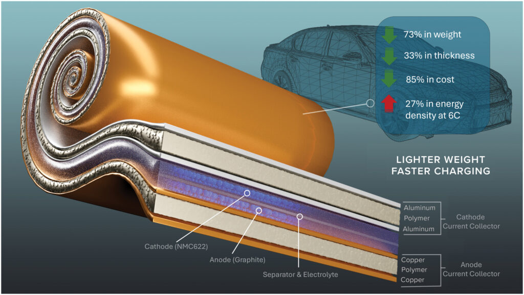
Interrupting the short circuit
Where the additive addresses chemical instability, the other innovation addresses electrical instability. The company has developed a metallised polymer current collector that acts as a built-in circuit breaker. Conventional current collectors use solid aluminium and copper foils. When an internal short occurs, these foils deliver the full energy of the cell to a single point, generating the heat that ignites thermal runaway.
This innovation replaces the solid foil with a polymer film metallised on both sides. When a short circuit occurs, the polymer heats, shrinks and pulls the metal away from the short site. The circuit fails locally, which electrically isolates the faulted region, allowing the cell to avoid catastrophic failure, albeit with some performance degradation. The result is a cell that can survive aggressive mechanical damage – including nail penetration and crushing – without igniting.
This is a radical form of redundancy built directly into the cell. It also brings significant secondary benefits. By replacing six microns of copper foil with one and a half microns of copper on a polymer substrate, this solution can significantly reduce current collector mass (up to ~75% copper reduction), translating to meaningful cell-level weight savings. The technology works across all form factors (pouch, prismatic and cylindrical) and is designed to be compatible with multiple chemistries including lithium-ion, sodium-ion and solid-state systems.
(Image: Envalior)
Critical industry tension
Despite their promise, both technologies face a common challenge: current safety regulations, such as China’s GB 38031-2025, assume that a cell will go into thermal runaway and then test whether propagation is prevented. They do not reward cells that prevent runaway in the first place. As the metallised film developer observes, the industry is “fixing one layer and ignoring the good stuff in other areas.” The result is a regulatory blind spot that undervalues cell-level safety innovations and discourages their adoption in cost-sensitive mass markets.
(Image: Kautex)
Managing heat and preventing propagation
If a cell does enter thermal runaway, the next line of defence is to contain that failure before it spreads to neighbouring cells. This layer operates at the interface between cells and the pack structure. It must perform two distinct functions: first, managing heat during normal operation and fast charging to prevent onset; second, slowing or blocking heat, flame and particle transfer if a cell does vent. Here we examine three promising new technologies that address these challenges.
Interface-level materials for two-stage defence
The first approach focuses on what might be called the “interface level gaps” – the spaces between cells, modules, cooling systems and the enclosure. These gaps become critical as architectures shift toward CTP designs, where separation and error margin shrink.
The company’s materials intervene at two stages. The first is pre-runaway mitigation. Thermally conductive adhesives and gap filler material based on polyurethane grades maintain consistent mechanical contact between cells and cooling units. This ensures efficient heat transfer during fast charging, preventing the localised hotspots that can trigger failure. Potting compounds add thermal mass around cells, absorbing and redistributing heat to slow temperature rise.
The second stage is propagation control. Once a cell has vented, silicone foams and potting compounds block the transfer of heat, flame and hot particles to adjacent cells. One notable formulation is non-intumescent and forms a hard ceramic layer when exposed to flame. This ceramic layer protects against repeated 1200 C
test cycles under the Torch-and-Grit (TaG)-style testing aligned with UL battery fire test methodologies, maintaining the structural integrity of the battery enclosure throughout the event.
Crucially, these materials operate passively and continuously. They do not rely on sensors, algorithms or external power. This makes them robust against the failure of active systems, but it also means that they must be engineered for the specific mechanical and thermal demands of each pack design.
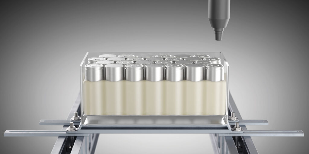
Potting to stop propagation, coating to protect the cabin
Potting and coating technologies are distinct approaches to interface protection. The first is designed specifically to prevent thermal runaway from propagating to neighbouring cells. By encapsulating cells or modules, the potting material contains the event to within a single cell, significantly reducing overall system risk. The material must perform during the venting and flame phases – a window of just seconds to minutes where peak temperatures and particle velocities are extreme.
The second is the application of coating to protect the passenger compartment by reinforcing the battery housing. Unlike potting, the coating continues to provide value even if propagation has already occurred. However, the developer notes a critical dependency: in CTP designs, venting occurs directly onto the coating, subjecting it to direct particle impact and flame impingement. This requires the coating to be not only thermally insulating but also mechanically robust. Performance is highly sensitive to venting design; bottom venting can substantially improve coating effectiveness.
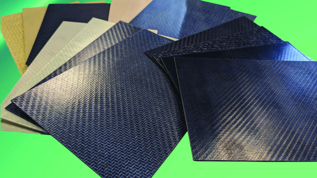
Composite barriers for thermal and particle protection
Continuous-fibre-reinforced thermoplastic composite material is another means of slowing heat flow at interfaces. Positioned between cells or modules, the material acts as a thermal barrier that delays the propagation of dangerous temperatures to neighbouring cells. At the pack level, it helps contain an ongoing thermal event, offering resistance to both heat and particle bombardment.
Validation is critical for any propagation barrier. The developer tests this composite material using the UL 2596 TaG method: a demanding standard that simulates the combined thermal and mechanical assaults of a real-world thermal runaway. At 2 mm thickness, the composite passes up to four test cycles, which is a benchmark that provides engineers with a quantifiable performance metric.
Taken together, these technologies reveal a clear engineering principle: passive thermal management materials must be formulated for the specific failure mode. The polyurethane and silicone formulator addresses interface gaps and ceramic layer formation. The potting and coating developer distinguishes between cell-to-cell potting and cabin-facing coatings. The composite material developer provides structural barriers validated to an industry test standard. In each case, the material’s effectiveness depends not only on its intrinsic properties but also on how it integrates with the pack’s venting design, cooling system and mechanical architecture.
Structural containment and gas management
If a thermal runaway event breaches the cell and the CTP barriers, the battery enclosure becomes the last line of structural defence. This layer must perform three functions simultaneously: contain the fire within the pack, direct hot gases away from passengers and sensitive components and maintain electrical isolation. Two technologies discussed here represent contrasting but complementary approaches at this layer, with one focusing on composite enclosure architecture and the other on protective coatings.
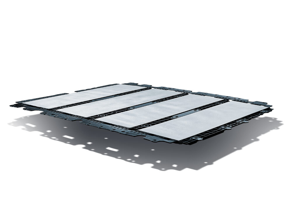
Composite enclosures with integrated venting
The first approach integrates battery cells directly into a structural composite enclosure, removing the intermediate module level to save weight and improve energy density. The enclosure is a sandwich structure combining a composite tray and top cover, with cell holders forming the structural core. This design offers several safety advantages.
First, the composite material is intrinsically non-conductive and non-corroding. Unlike metal enclosures, it offers inherently high electrical resistivity, reducing reliance on additional insulation layers over the full vehicle lifetime without requiring additional corrosion protection.
Second, and more critically, the developer has integrated venting features directly into the enclosure using its one-shot moulding process – a capability that is difficult to achieve with metal designs. When a cell vents, gases are guided downward into a protected gap between the enclosure and an underbody protection plate, rather than allowing uncontrolled side jetting into the passenger compartment or adjacent cells. This separation of electrical terminals from pressure relief channels – a principle echoed in other designs – reduces the risk of arcing and directs flames away from occupants.
The third advantage is that the composite structure has demonstrated robust fire performance. In system-level tests conducted according to GB 38031, the battery enclosure showed no burn-through for more than 15 minutes, exceeding the regulatory requirement of five minutes.
Coatings as a secondary containment layer
A safety coating can provide a second and different form of containment. Positioned on the inside of the battery housing, the coating protects the passenger compartment by reinforcing the enclosure against thermal and mechanical attack, its developer emphasises. Unlike potting materials that prevent cell-to-cell propagation, the coating continues to provide value even after propagation has occurred.
However, the company highlights a critical design dependency that engineers must consider. In module-based pack designs, venting gases travel through internal pathways before reaching the housing. In CTP architectures, by contrast, venting occurs directly onto the coating, subjecting it to direct particle impact and flame impingement. This shifts the performance requirements significantly: the coating must be not only thermally insulating but also mechanically robust enough to withstand high-velocity hot particles. It is worth noting that venting design – particularly bottom venting that avoids direct particle impact – can strongly influence coating effectiveness.
Design implications for engineers
These responses reveal two important principles for enclosure design. First, venting pathways must be engineered as a system, not as an afterthought. The direction, pressure and particle load of vent gases determine the requirements for coatings, barriers and structural elements. Second, material choices have cascading effects. Composites offer corrosion resistance and design flexibility but must be validated for fire exposure – a misunderstanding that the developer actively addresses through demonstrators and real-world vehicle testing. Coatings offer passenger protection but their performance depends on upstream venting design.
Underbody protection
The final layer in the safety stack is also the first line of physical defence. Before a cell can fail electrically or chemically, it must survive the mechanical environment of the vehicle. Road debris, stones, gravel impacts and scraping loads from driving over rocks or curbs can locally penetrate the battery enclosure, initiating cell damage that may lead to thermal runaway hours or days later. Underbody protection addresses this hazard at the source, preventing mechanical intrusion from reaching the cells in the first place.
Our enclosure developer also offers a lightweight, thermoplastic composite shield mounted beneath the battery pack. Its primary function is to distribute and absorb impact energy, avoiding the local puncture that is a common failure mode of metal underbody plates. In defined ballistic impact and penetration tests, the composite structure prevents objects from breaching the protection layer. In scraping and oblique impact tests, it withstands loads without surface penetration.
This shield is scalable across different vehicle platforms and risk profiles.
For lower-severity load requirements, an all-composite solution provides adequate protection with minimal weight. For medium to high load cases – such as off-road capable vehicles or applications subject to severe debris –
a metal-composite hybrid design adds additional energy absorption. For the highest load and energy absorption classes, a hybrid sandwich architecture is available. This scalability allows OEMs to tailor protection to specific use cases.
A notable feature is the potential integration of a sensor mat within the shield. When an impact occurs, the sensor detects the area and severity of any damage, providing data to the vehicle’s safety systems. This allows the BMS or driver alert system to determine whether the battery pack has been compromised, potentially preventing a delayed thermal runaway event and avoiding pack replacements when no damage has occurred.
Supporting thermal runaway venting
The underbody shield also serves a secondary, less obvious safety function during a thermal event. The company has designed its system so that the enclosure’s venting features guide hot gases downward into the protected gap between the enclosure and the shield. The shield then forms a protected evacuation path, channelling gases to an emergency vent and outside the pack.
Limits of mechanical protection
One respondent’s perspective provides a necessary caution. Even with perfect underbody protection, cells can still fail internally owing to manufacturing defects, ageing or electrical abuse. Mechanical protection is necessary but not sufficient. A truly safe battery requires layers that address electrical and chemical hazards at the cell level, not just mechanical hazards at the underbody. Robust enclosures and shields prevent one class of initiation mechanism; they do not eliminate the need for robust cell chemistry and thermal management layers above it.
Emerging hazards, future gaps
Looking five years ahead, the five companies identify a range of emerging hazards.
One points to the interaction between ultra-fast charging, battery ageing and second-life applications. As batteries are pushed harder earlier in life and then repurposed for stationary storage, factors such as material fatigue, swelling and thermal unpredictability become more pronounced. The company is responding by developing materials that maintain performance over extended service lives and support disassembly for repair and recycling.
Another warns that all-solid-state batteries, often promoted as inherently safe, may have underestimated fire risks, emerging evidence suggests. The company is conducting its own fire tests on new chemistries before they reach market maturity, rather than relying on vendor claims.
A third identifies a different bottleneck: the shortage of recycled raw materials. Customer requirements for recycled content in plastic components will soon exceed global recycling capacity. Its response has been to establish mechanical and solvent-based recycling programs for end-of-life enclosures to address this.
Safety rating gap
Perhaps the most fundamental critique, however, is that the industry lacks a battery safety rating system comparable to crash-test stars for vehicles. Currently, a battery either passes a regulatory standard or it does not. Passing conveys no information about how much safer one cell is than another. As one respondent observes, every battery that catches fire has passed the existing cell-level standards. This creates no incentive for manufacturers to exceed minimum requirements.
The consequence is that cell-level innovations – such as the circuit breaker or the electrolyte additive – are undervalued in cost-sensitive mass markets. The industry is perfecting pack-level propagation prevention while assuming cells will fail, rather than rewarding cells that prevent failure in the first place. Addressing this gap will require regulators and industry bodies to develop tiered safety metrics that drive innovation across all layers of the Swiss cheese model.
Acknowledgements
The author would like to thank the following for their help with this article: Ryan Smith, global marketing director at Dow; Juergen Selig, advanced development expert battery system at Envalior; Dr Kim Kreiskoether, battery safety expert at Henkel; Jack Hooker, battery systems engineer (cell-to-pack) & Daniel Heidrich, battery systems engineer (underbody protection) at Kautex; Dr Brian Morin, CEO of Soteria Battery Innovation Group.
Some suppliers of battery safety
Alkegen www.alkegen.com
AkzoNobel www.akzonobel.com
Aspen Aerogels www.aerogel.com
Dow www.dow.com
DuPont www.dupont.com
Envalior www.envalior.com
Henkel www.henkel.com
Kautex www.kautex.com
SABIC www.sabic.com
Soteria www.soteriabig.com
ONLINE PARTNERS

